1
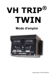
® VH TRIP TWIN USER MANUAL 1305130 Mode demploi VH TRIP TWIN EN.doc INDEX Introduction: What’s a VH TRIP TWIN?............................................. Erreur ! Signet non défini. I - Overview : .............................................................................................. Erreur ! Signet non défini. Technical Specifications (subjet to change) : ................................ Erreur ! Signet non défini. VH TRIP TWIN® Controls:.............................................................................................................. 2 Probes Installation : ............................................................................ Erreur ! Signet non défini. Car Installation : ................................................................................... Erreur ! Signet non défini. Wiring : .................................................................................................... Erreur ! Signet non défini. VH TRIP TWIN® Test: ...................................................................................................................... 5 III - VH TRIP TWIN® Calibration : .................................................................................................... 6 Step 1: Probe Calibration. ............................................................................................................. 6 Step 2 : Calibration. ........................................................................................................................ 7 IV – USING your VH TRIP TWIN® : ....................................................... Erreur ! Signet non défini. 1. "Normal" Mode: ................................................................................ Erreur ! Signet non défini. 2. « Distance Recovery » Mode : ...................................................... Erreur ! Signet non défini. V – Remote Displays Installation :................................................................................................ 10 1. Installation : ................................................................................... Erreur ! Signet non défini. 2. Wiring: ............................................................................................. Erreur ! Signet non défini. 3. Use ................................................................................................... Erreur ! Signet non défini. VI – Troubleshooting ............................................................................... Erreur ! Signet non défini. Introduction: What’s a VH TRIP TWIN? The VH TRIP TWIN® is a measuring device giving you precise information on the distance you have travelled from a given point. Easy to set up, it will require care when installing and calibrating to make sure that the information given is as accurate as possible. We wish you many happy miles with your VH TRIP TWIN® but please read on to make sure you make the most of it. 1 I - OVERVIEW: Technical Specifications (subject to change) : Power: 6 to 13 Volts ; Polarisation: Negative Earth Maximum consumption: 1 A ; Temperature range: -10°C à 30°C ; Warranty: 24 months. Manufacturer Return To Base. Can be used in Kms or Miles VH TRIP TWIN® Key Buttons and Indicators: Key : 1 2 3 4 5 6 7 8 9 10 11 12 13 14 15 Unit ON/OFF Switch Probe 1 calibration Switch Probe 1 calibration light Probe 2 calibration Switch Probe 2 calibration Light Probe 1 distance display (accuracy 10 meters) Probe 2 distance display (accuracy 10 meters Display Reset Buttons Probe 1 Rotary switch Probe 2 Rotary switch Distance recovery switch (with probe 1 only) Distance recovery light Power/probes connector Probe 1 remote display connector Probe 2 remote display connector 2 II - VH TRIP TWIN® Installation: Distance Probe Installation: Your VH TRIP TWIN® is compatible with most 2 or 3 wires probes available on the market : - Speedo cable probes; - Induction Probes (ABS Sensor, engine rotation, …) ; We would however recommend to use a specific VH TRIP TWIN® probe which can be purchased from one of our distributors. To avoid interferences, make sure to keep the probe wires away from HT Leads, alternator and any other electric equipment generating interferences. Protect the probe and leads from projections which could damage or severe the leads. Positioning the probe : To ensure maximum accuracy, we recommend the probe to be fitted on a non-driven wheel. Where possible, fit the probe to the rear (trailing) of the vertical centre line on the wheel assembly. Position the probe so that it ‘looks’ at the heads of the bolts which secure the brake disc to the wheel hub of a non-driven wheel. In some cases it might be more convenient to look at holes in a metal surface. The probe must be co-axial with the centre line of the bolts and the front face of the probe must be parallel with the heads of the bolts. Cup-head [Allen] head bolts do not give the probe a good signal and should not be used if at all possible. Distance between the probe and the bolts should be 1mm to 3mm. Universal Speedo cable probe : For accuracy and reliability reasons, we do not recommend using a speedo probe. Your VH TRIP TWIN® ® is however compatible with this type of probe. Please refer to your probe installation manual for set up. Car Installation: The VH TRIP TWIN® ® needs to be placed away from the driver direct line of sight and in no way interfere with the driving of the vehicle. Please also make sure that it is out of arms way in case of an accident. Your VH TRIP TWIN® ® can be installed on any support using the casing fixing tabs and screws. VH TRIP TWIN® Connector: The VH TRIP TWIN® is supplied with a detachable connector which can stay in your car should you want to take your VH TRIP TWIN® out. Additional connectors can be purchased to equip several vehicles or plug in several probes. 3 Connections: Please respect the wiring below Wheel or Speedo probe Connection Connector Fuse Red Brown Blue Green Brown Blue Green Probe 2 Probe 1 Black Gearbox Probe Connexion Black Red Blue Green Probe 1 Blue Green Brown Probe 2 2200Ω Brown 2200Ω Connector Fuse Place a 2200 Ohms resistor between the Blue and Brown wires. Warning: Make sure this resistor is properly insulated and cannot get into contact with any metallic part. . 4 VH TRIP TWIN® Connection Earth Power (+6 à +12 volts) Probe 1 out (+ 12V) Probe 1 In Earth (Probe 1) Probe 1 Out (+ 12V) Probe 2 in Earth (Probe 2) Probe 1 Function Probe 2 Wire Colour Black Red Brown Blue Green/ Yellow Brown Blue Green / Yellow If using a 2 wire probe, only connect the blue and brown wires. Please check all connections and wiring before powering your VH TRIP TWIN® Different type of probes can be used on the same VH TRIP TWIN®. VH TRIP TWIN® TEST: Before powering the unit, make sure that switches ( 2 et 4 ) are to the left. Switch unit on ( 1 ). Illumination lights should come on. LED ( 12 ) should be green and LED ( 3 ) OFF. Slide calibration switch ( 2 ) to the right. LED ( 3 ) should come on. Move car forward, display 6 should start counting (probe 1 is therefore working) Slide switch ( 2 ) to the left and push probe calibration switch ( 4 ) to the right. LED ( 5 ) comes on. Move car forward, display ( 7 ) starts counting (probe 2 is working) Your VH TRIP TWIN is ready to be set up. Note : If LEDs ( 3 or 5 ) start flashing when sliding switches back to initial position, your calibration is incorrect. Please refer to Troubleshooting guide. 5 III - VH TRIP TWIN® Calibration : Your VH TRIP TWIN® is easy to calibrate. Step 1: Probes Calibration. 1. Switch Unit On. 2. Reset both displays to Zero by pressing reset buttons ( 8 ). 3. Slide Probe 1 calibration switch ( 2 ) to the right. LED ( 3 ) comes ON. 4. Turn the wheel on which probe 1 is installed 3 times (no more – no less). 5. Slide Probe 1 calibration switch ( 2 ) back to initial position 6. Slide Probe 2 Calibration switch ( 4 ) to the right. LED ( 5 ) comes ON. 7. Turn the wheel on which probe 2 is installed 3 times (no more – no less). 8. Slide Probe 2 calibration switch ( 4 ) back to its initial position 9. Switch unit OFF Your VH TRIP TWIN® is now ready to be calibrated. If light ( 3 or 5) flashes when sliding Probe Calibration Switch back to the left, your calibration is incorrect. Please refer to the Troubleshooting guide at the end of this instruction manual. WARNING: If the Probe Calibration Switch is moved by mistake, the probe calibration process will have to be repeated. 6 Step 2: Calibration. This is how to calibrate Display 1 (Probe 1). The same procedure applies to Display 2 (Probe 2) using coding wheel ( 10 ) and display ( 7 ). Take a pocket calculator with you and find a straight bit of road with distance markers 1. Put rotary switches ( 9 ) to Zero. Reset display ( 6 ) to Zero using button ( 8 ) 2. Drive between two markers (for example 1000 meters) Your VH TRIP TWIN® display will start counting. WARNING : Do not drive at more than 20 MPH or you may damage the equipment. 3. Once you have driven your 1000 meters, make a note of the value on the displays. 4. Then use the following formula : Distance travelled in meters/miles Display reading 7 5. Round up to the nearest 3 decimal points and input this value into the rotary wheels. As per our example: 1000 717 = 1.3947001… ≈ 1.395 Input 1395 on the rotary wheels Your VH TRIP TWIN® is now calibrated. NOTE : Greater accuracy can be obtain by driving on longer distances to calibrate your VH TRIP TWIN® . We recommend to do it over a 4000m distance. 8 IV – USING your VH TRIP TWIN® : 1. "Normal" Mode: At the start of each stage, we recommend the following: 1. Switch your VH TRIP TWIN® OFF then back ON 2. Reset all displays to ZERO. 3. Make sure that the Distance Recovery switch is on +. 4. Make sure your rotary wheels are correctly set up (especially if you change wheels / tyres between stages). Nothing more to do but drive and check the accuracy of your readings on the stage which you can easily do by using our Average Trip Box (available from your VH TRIP TWIN® distributor). 2. “Distance Recovery” Mode : If you suddenly realise that you are off course, just follow these easy steps: 1. As you make your U turn, slide the Distance Recovery switch (10) to -. 2. Displays (6) will then be frozen and LED (12) turns Red . 3. Once back on the right course, slide the Distance Recovery switch (10) back to +. 4. Carry on the right route, LED ( 12 ) will turn to Green again once you have driven the same distance as you did from the U Turn, therefore recovering the distance travelled and correcting your mistake. Note : Displays ( 6 ) will stay frozen until your VH TRIP TWIN® has corrected the distance. Should you take a wrong turn again before re-joining the right route, repeat same procedure, distances will automatically add up. 9 V – Remote Displays Installation: 1. Installation: The remote displays must not be fixed by putting screws through them or this will void the warranty. 2. Wiring: These displays are easily connected to your VH TRIP TWIN® by simply plugging them as follow: ( 14 ) for Probe 1 ( 15 ) for Probe 2 3. Use: The remote displays work exactly as the ones on your VH TRIP TWIN® and can be reset to Zero by simply pressing the central button. Guide de dépannage Vous devez impérativement suivre cette procédure avant toute demande de SAV. 10