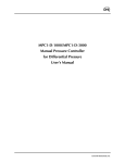
1
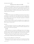
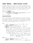
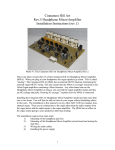
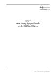
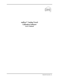
CFM-10
Installation Guide
North American Office:
5600 General Washington Drive
Suite B211, Alexandria, VA 22312
USA
Toll Free: (800) 272-4775
T: (703) 933-0024
F: (703) 933-0025
European Office:
Twickenham Avenue
Brandon, Suffolk
IP27 0PD
United Kingdom
T: +44 (0)1842 814814
F: +44 (0)1842 813802
www.ssosystems.com
Contents
Introduction ........................................................................................................................................ 3
A Two Minute Guide......................................................................................................................... 4
Assembly differences ------------------------------------------------------------------------------------------------- 4
Full Installation Guide....................................................................................................................... 5
Connections to the MultiSystem Network ..................................................................................... 5
Direct Connection ----------------------------------------------------------------------------------------------------- 6
Power Wiring...................................................................................................................................... 7
Drawstops and Tabstops ................................................................................................................... 7
Luminous Stops.................................................................................................................................. 7
Set Piston and General Cancel.......................................................................................................... 7
SCOPE™ Piston.................................................................................................................................. 8
Ordinary Pistons & Piston Lamps ................................................................................................... 8
Blind Pistons and Lamps .................................................................................................................. 8
Blind Switches .................................................................................................................................... 9
10-Way Level Selector ....................................................................................................................... 9
Blind Check, Clear and Copy Switches........................................................................................... 9
Lock switch and Indicator Lamp ................................................................................................... 10
Using LED's ...................................................................................................................................... 11
Commissioning ........................................................................................................................ 12
Introduction
This MultiSystem is fitted with an integrated Capture System; we call it Capture For MultiSystem or
CFM for short.
In the package you will find an operating guide for the organist. Please leave this in the console
when you have completed the installation. We are always happy to supply extra copies, should you
require them. This document is concerned only with the installation of the system.
CFM systems are available in three models, CFM10, CFM25 and CFM300. Each system is quite
different, and to avoid confusion we have provided separate installation manuals for each system.
This manual is for CFM-10 only.
Copyright,© 1602 Group Ltd, 1995. All rights reserved. SSOS Stock Number 82S6PC10 CFM-10, capture for multisystem, and scope are
trademarks of 1602 Group Ltd.
A Two Minute Guide
Even if you are not familiar with our MultiSystems and MultiLevel Capture Systems, it is possible to
adapt very easily to the CFM system. The two minute guide should get you up and running with the
minimum of fuss.
CFM is a supplementary product to the MultiSystem.
In addition to the MultiSystem, the CFM-10 adds:
•
An extra processor box containing the CFM processor unit.
•
A small a.c. power supply that must be connected to a source that remains on after the
main power is turned off.
•
Outputs on the console plane to drive the drawstops (on and off coils).
•
Inputs on the console plane for the level change switch and Piston Inputs, Set, General
Cancel etc.
Assembly differences
The CFM-10 processor box must be added to the MultiSystem Network. It can be added anywhere
in the network that is suitable, using link protection boards and a coloured ribbon cable. Normally
next to the console processor. An NP linker (see below for details) may be used to simplify this
connection.
The console will require a cut-out for the level change switch and capture functions as ordered.
CFM-10 Installation Guide
Revision: 8th May 2013
Page 4
Full Installation Guide
The following instructions are intended to be read in conjunction with the MultiSystem Installation
Guide which was delivered with the MultiSystem. If you are upgrading a system and the
information has been lost, please contact us and we will gladly supply a fresh copy from our
archives.
Connections to the MultiSystem Network
It is necessary to connect the CFM-10 system to the MultiSystem Network.
There are two ways to do this.
1. Normally the CFM-10 system can be fitted less than 0.5 metres (18 inches) from another
MultiSystem processor. In this case the two coloured ribbon cables can be connected directly
using an NP linker.
2. When greater distances are required, the cable entry to the system must be taken through a
link protection board at each end. This is identical to a MultiSystem installation. Unless this
has been specified at the time of ordering you will require two more Link Protection boards,
which are available ex-stock from your local SSOS office, part number 62310260.
CFM-10 Installation Guide
Revision: 8th May 2013
Page 5
Direct Connection
The system will be supplied with a multicoloured ribbon cable for each black box. The cable plugs
into the 25 way "D type" connector in the box at one end, and has 3 small 10 way connectors at the
other end of the cable. These connectors are labelled NEXT, PREVIOUS and SPARE.
For more details on how these connectors relate to the MultiSystem, please refer to the MultiSystem
Installation Guide.
The CFM-10 system is supplied with a small circuit board with 2 connectors, known as an NP Linker.
If you wish to connect the CFM-10 system directly, plug the NEXT connection of one ribbon cable
and the PREVIOUS connection of the other ribbon cable into the board. Which NEXT and
PREVIOUS you chose will be determined by the existing wiring on the MultiSystem. It does not
matter to the CFM-10 system, either will operate perfectly.
CFM-10 Installation Guide
Revision: 8th May 2013
Page 6
Power Wiring
The CFM system requires power from a local DC rectifier (T/R). The box is fitted with a pair of
terminals to connect to the supply. This supply must be reasonably stable and free from electrical
noise; most commercially available units are suitable. Unlike other SSOS products which are limited
to a maximum of 24 volts, the MultiSystem products will operate over a range between 12 and 32
volts.
The CFM 10 system also requires an additional a.c. power source that is normally on. As a minimum
this supply must remain on for five minutes after the main supply is switched off so it is OK to
remove the power for maintenance.
The system will not operate satisfactorily from DC supplies which are provided by a rotary
generator, as the interference level is far too high.
Drawstops and Tabstops
Drawstops and tabstops require three connections to the MultiSystem as well as one power
connection per stop.
•
•
•
•
The switch contact of the stop unit connects to the stop or coupler input on the console plane.
The on coil of the stop unit connects to the on coil output on the console plane.
The off coil of the stop unit connects to the off coil output on the console plane.
The switch feed and the on and off coil returns all connect to T/R positive.
The switch inputs are suitable for use with mechanical switches, reed switches or electronic switches.
The on and off coil outputs are equipped with 'back EMF' or 'spark' suppression.
Luminous Stops
Luminous stops require two connections to the MultiSystem as well as one power connection per
stop.
•
•
•
The switch contact connects to the stop or coupler input on the console plane.
The stop lamp connects to the stop lamp output on the console plane.
The switch feed and the lamp return both connect to T/R positive.
The switch inputs are suitable for use with mechanical switches, reed switches or electronic switches.
Set Piston and General Cancel
•
•
•
The set piston should be wired to the set input on the MultiSystem console plane
The general cancel piston should be wired to the general cancel input on the MultiSystem
console plane.
The feed to both set and general cancel should connect to T/R positive.
CFM-10 Installation Guide
Revision: 8th May 2013
Page 7
SCOPE™ Piston
Scope is a new feature which allows the organ builder and organist to define which stops are
affected by which pistons.
Scope should be mounted as a piston adjacent to the set piston, as it needs to be operated by the
same hand that presses the set piston.
If it is not desirable to mount Scope on the console, it should be wired to a toggle switch behind the
music stand or in the back of the console.
Important Note: Scope is required for commissioning.
• One side of the Scope piston should be wired to the Scope input on the MultiSystem console
plane.
• The other side of the Scope piston should be wired to T/R positive.
Ordinary Pistons & Piston Lamps
MultiSystem makes no differentiation between General pistons, Divisional pistons, and reversers.
These are all referred to as Ordinary Pistons. Their function will be set during commissioning.
The MultiSystem console plane documentation will list the ordinary pistons as piston 1, piston 2, etc.
•
•
•
•
•
We recommend that General pistons are wired to the first piston inputs, followed by divisional
pistons, and finally reversers
The feed to the piston contacts should connect to T/R positive
If luminous pistons are fitted, their lamps should be connected as follows:One side of each lamp should be connected to the Piston Lamp output on the MultiSystem
console plane which corresponds tohte piston
The return for the piston lamps should connect to T/R positive
Blind Pistons and Lamps
Blind Pistons are those which are reversible, i.e. they turn on when the piston is first pressed, and
they turn off when it is pressed a second time. They will normally have an indicator lamp to show
whether they are on or off.
MultiSystem makes no differentiation between Inclusive Tutti (or Sforzando) pistons, Exclusive
Tutti pistons, and Ventil pistons. These are all referred to as Blind Pistons. Their function will be set
during commissioning.
The MultiSystem console plane documentation will list the pistons as blind piston 1, blind piston 2,
etc.
•
•
•
•
Wire each blind piston to one of the blind piston inputs as listed in the MultiSystem console
plane documentation.
The feed to the piston contacts should connect to T/R positive.
One side of each lamp should be connected to the Piston Lamp output on the
MultiSystem console plane which corresponds to the piston.
The return for the piston lamps should connect to T/R positive.
CFM-10 Installation Guide
Revision: 8th May 2013
Page 8
Blind Switches
Blind Switches are those which have an on and an off position.
MultiSystem makes no differentiation between Inclusive Tutti switches, Exclusive Tutti switches,
and Ventil switches. These are all referred to as Blind switches. Their function will be set during
commissioning.
The MultiSystem console plane documentation will list the switches as blind switch 1, blind switch 2,
etc.
•
•
Wire each blind switch to one of the blind switch inputs as listed in the MultiSystem console
plane documentation.
The feed to the switch contacts should connect to T/R positive.
10-Way Level Selector
Memory level selection on CFM-10 is by means of an ten way switch.
•
•
The switch common should be wired to T/R positive.
The ten contacts should be wired to the ten level select inputs on the
MultiSystem console plane.
6
5
4
8
7
3
Connect pins 1-8
to memory level inputs
as shown in connector list.
2
Connect tag marked
A to Positive
A
1
Blind Check, Clear and Copy Switches
CFM-10 is supplied with 3 switches, one each for Blind Check, Clear and Copy. Each of these
switches has a built-in lamp.
The Blind Check switch is only required on systems fitted with blind functions such as tuttis, ventils
and sforzandos.
•
•
•
One side of each switch should be connected to either the Blind Check input, the Clear input, or
the Copy input on the MultiSystem console plane.
One side of each lamp should be connected to either the Blind Check Lamp output, the Clear
Lamp output, or the Copy Lamp output on the MultiSystem console plane.
The other side of the switch and the lamp should be connected to T/R positive.
CFM-10 Installation Guide
Revision: 8th May 2013
Page 9
A rear view of the switch/lamp. The lamp connects to contacts 'a' and 'b'.
Contacts marked 3 and 4 are normally open and should be used for the
switch wiring.
Lock switch and Indicator Lamp
The lock switch is a momentary action, key operated switch used for locking and unlocking levels.
The lock indicator lights whenever the currently selected level is locked.
The lock switch is usually supplied by SSOS.
•
•
•
•
Connect Pin 3 to positive.
Pin 4 connects to the lock switch input on the MultiSystem console plane.
The lock indicator lamp should be mounted next to the lock switch. It should be wired as
follows.
One side of the lock indicator lamp connects to positive.
The other side of the lamp connects to the lock lamp output on the MultiSystem console plane.
Lock switch showing connections, use only pins 3 and 4.
CFM-10 Installation Guide
Revision: 8th May 2013
Page 10
Using LED's
LED's are solid state devices which emit light. They may be used in place of lamps if certain
conditions are met.
LED's only work one way round. The cathode connects to the negative end of the circuit and is
indicated by the shortest lead, or by a "flat" on the body of the LED.
LED's work at voltages between 2V and 3V. To prevent damage, they require a resistor in series
with them in order to limit the current flowing through them. The resistor has two values, its
resistance measured in ohms, and its power measured in watts.
To calculate these two values use the following formulae:resistance = ((T/R voltage - 2) ´ 100) ohms (Ω)
power = ((T/R voltage - 2) ÷ 100) watts (W)
Exact values are not necessary, but larger values are safer than lower ones.
Suitable resistors for a variety of T/R voltages are shown below
12V
1K0 (1000Ω) 5% 0.25W (min.)
15V
1K3 (1300Ω) 5% 0.25W (min.)
18V
1K6 (1600Ω) 5% 0.25W (min.)
24V
2K2 (2200Ω) 5% 0.25W (min.)
All of the above assume LED's rated at a current of 10mA. These values are safe for use with any
LED.
Some LED's are recommended to have a higher current of 20mA. In this case, the value of the
resistor will need to be reduced. The resistance should be halved, and the power should be doubled.
Some LED's are available with built in resistors. These will usually be labelled as 12V or 24V, and do
not require a resistor when used at their rated voltage.
CFM-10 Installation Guide
Revision: 8th May 2013
Page 11
Commissioning
Having wired all of the above, the system can now be commissioned.
The first stage is to check the connection of the on and off coils.
• Connect a positive lead to the pin marked test input in the connector list for the console plane.
• Press General Cancel.
• In test mode each stop's on and then off coil are fired in sequence.
• If correctly wired, each stop will move on and then off. In this way wiring errors can be easily
identified and corrected before proceeding.
A stop not moving on, may also not move off. Try putting stops on and checking to see if they go off
during test. It is not necessary to stop the test to do this. A stop not going on but going off has a
faultly off coil. A stop not moving at all may have the on and off coils swapped.
A stop not going off, but does go on, may have a faulty stop switch - not giving a positive to the
CFM-10 stop input. Try testing each as follows:Stop switch: With a test lamp connected to negative and all stops on, test mode not selected. Check
each stop switch has a positve voltage, the lamp will light.
Off coils: After checking stop switches. Connect test lamp to positive. Switch first stop on, connect
test lamp to first stop, push General Cancel, lamp should flash briefly, repeat for next stop until
complete.
Referring to the User Manual, carry out the following steps:
• Select Level one.
• Set the Scope of every ordinary piston.
• Set the Scope of all blind pistons.
• Set all the blind pistons.
Within the system, momentarily connect a positive lead to the default level input. This will cause the
current scopes and blind functions, which have just been set on level one, to be stored for later use.
Referring to the User Manual, now carry out the following steps:
• Select Level two. Set any piston with any selection of stops on level two. It is not possible
to clear a level if it is empty.
• Clear Level two.
• Clear Level two a second time.
• Repeat the above operations for the remaining levels (3-8).
This will set the default scopes and blind functions on each of the levels. It will leave all of the
pistons blank, ready for use.
It is also possible to set different Sopes in different levels. Full instructions for this and other
functions may be found in the user manual.
CFM-10 Installation Guide
Revision: 8th May 2013
Page 12