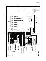
1
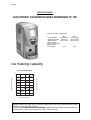
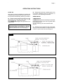
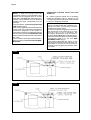
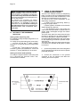
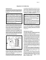
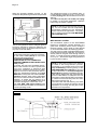
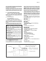
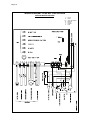
Page 1
Page 1
SERVICE MANUAL
TC 180
Electronic
counter nugget
ice dispenser
MS 1000.59 REV. 03/2005
Page 2
Page 2
TABLE OF
CONTENTS
Table of contents
Specifications
page
2
3
GENERAL INFORMATION AND INSTALLATION
Introduction
Unpacking and Inspection
Location and levelling
Electrical connections
Water supply and drain connections
Final check list
5
5
5
5
6
6
OPERATING INSTRUCTIONS
Start up
Operational checks
7
8
PRINCIPLE OF OPERATION (How it works)
Water circuit
Refrigerant circuit
Mechanical system
Operating pressures
Components description
11
11
12
13
14
ADJUSTMENT, REMOVAL AND REPLACEMENT PROCEDURES
Wiring diagram
Service diagnosis
17
19
MAINTENANCE AND CLEANING INSTRUCTIONS
General
Icemaker
Cleaning instructions of water system
21
21
21
Page 3
Page 3
SPECIFICATIONS
ELECTRONIC COUNTER NUGGET DISPENSER TC 180
Important operating requirements:
MIN
- Air temperature
10°C (50°F)
- Water temperature 5°C (40°F)
- Water pressure
1 bar (14 psi)
- Electr. voltage
variations fromvoltage
rating specified
on nameplate
-10%
MAX
40°C (100°F)
35°C (100°F)
5 bars (70 psi)
+10%
ice making capacity
AIR COOLED MODELS
°C
Kg.
140
10
120
21
110
100
32
90
38
80
AMBIENT TEMPERATURE
ICE PRODUCED PER 24 HRS.
130
70
60
32
27
21
15
10 o°C
WATER TEMPERATURE
NOTE. The daily ice-making capacity is directly related to the condenser air inlet temperature, water
temperature and age of the machine.
To keep your SCOTSMAN NUGGET DISPENSER at peak performance levels, periodic maintenance
checks must be carried out as indicated on page 21 of this manual.
Page 4
Page 4
SPECIFICATIONS
TC 180 - MACHINE SPECIFICATIONS
Model
Cond. unit
TC 180 AS
Basic electr.
230/50/1
Finish
Air
S. Steel
Amps
Start
Amps
3.4
18
Watts
590
Comp. HP
3/8
Electric power cons.
Kwh per 24 HR
13,2
Ice bin
cap
Water req.
lt/24 HR
5 Kg.
135
Nr. of wires
3 x 1.5 mm2
Amps fuse
10
Page 5
Page 5
GENERAL INFORMATION AND INSTALLATION
A. INTRODUCTION
This manual provides the specifications and the
step-by-step procedures for the installation, startup and operation, maintenance and cleaning for
the SCOTSMAN TC 180 counter nugget ice
dispenser.
Their ice making systems are thoroughly tested
providing the utmost in flexibility to fit the needs
of a particular user.
NOTE. To retain the safety and performance
built into this icemaker, it is important that
installation and maintenance be conducted
in the manner outlined in this manual.
B. UNPACKING AND INSPECTION
1. Call your authorized SCOTSMAN Distributor
or Dealer for proper installation.
10. Remove the manufacturer’s registration card
from the inside of the User Manual and fill-in all
parts including: Model and Serial Number taken
from the data plate.
Forward the completed self-addressed
registration card to SCOTSMAN EUROPE
factory.
C. LOCATION AND LEVELLING
WARNING. This Ice Dispenser is designed
for indoor installation only. Extended
periods of operation at temperature
exceeding the following limitations will
constitute misuse under the terms of the
SCOTSMAN Manufacturer’s Limited
Warranty resulting in LOSS of warranty
coverage.
5. Remove all internal support packing and
masking tape.
1. Position the unit in the selected permanent
location.
Criteria for selection of location include:
Min
Max
Air Temperature
10°C
40°C
Water Temperature
5°C
35°C
Water pressure
1 bar
5 bar
Voltage
-10% +10%
(Compared to the nameplate)
Service access: adequate space must be left for
all service connections through the rear of the ice
maker.
This machine is air cooled and sucks air through
the left side panel and blows air out the rear side
of the top panel. Do not install the machine where
the left side air flow might be blocked. A minimum
clearance of 15 cm is required.
It is important that the machine be installed in a
location where it has enough space around it to
be accessible for service, and minimum of 150
mm be allowed at the left and upper side for air
circulation. Try to avoid hot, dirty and crowded
locations.
6. Check that refrigerant lines do not rub against
or touch other lines or surfaces, and that the fan
blades move freely.
NOTE. It is imperative to do not place on top
of the machine any sort of goods and leave
the upper lowers open for proper air exhaust.
2. Visually inspect the exterior of the packing
and skid. Any severe damage noted should be
reported to the delivering carrier and a concealed
damage claim form filled in subjet to inspection of
the contents with the carrier’s representative
present.
3. a) Cut and remove the plastic strip securing
the carton box to the skid.
b) Cut open the top of the carton and remove
the polystyre protection sheet.
c) Pull out the polystyre posts from the
corners and then remove the carton.
4. Remove the top and sides panels of the unit
and inspect for any concealed damage. Notify
carrier of your claim for the concealed damage
as stated in step 2 above.
7. Check that the compressor fits snugly onto
all its mounting pads.
8. Use clean damp cloth to wipe the surfaces
outside of the cabinet.
9. See data plate on the rear side of the unit
and check that local main voltage corresponds
with the voltage specified on it.
CAUTION. Incorrect voltage supplied to
the icemaker will void your parts
replacement program.
D. ELECTRICAL CONNECTIONS
See data plate for current requirements to
determine wire size to be used for electrical
connections. All SCOTSMAN icemakers require
a solid earth wire.
All SCOTSMAN ice machines are supplied from
the factory completely pre-wired and require
only electrical power connections to the wire
cord provided at the rear of the unit.
Make sure that the ice machine is connected to
its own circuit and individually fused (see data
plate for fuse size).
Page 6
Page 6
The maximum allowable voltage variation should
not exceed -10% and +10% of the data plate
rating. Low voltage can cause faulty functioning
and may be responsible for serious damage to
the overload switch and motor windings.
NOTE. All external wiring should conform to
national, state and local standards and
regulations.
WATER DRAIN
The recommended drain tube is a plastic or
flexible tube with 18 mm (3/4") I.D. which runs to
an open trapped and vented drain. When the
drain is a long run, allow 3 cm pitch per meter
(1/4" pitch per foot).
Install a vertical open vent on drain line high point
at the unit drain connection to ensure good
draining.
The ideal drain receptacle is a trapped and
vented floor drain.
Check voltage on the line and the ice maker’s
data plate before connecting the unit.
NOTE. The water supply and the water drain
must be installed to conform with the local
code. In some case a licensed plumber and/
or a plumbing permit is required.
E.
WATER SUPPLY AND DRAIN
CONNECTIONS
GENERAL
When choosing the water supply for the ice flaker
consideration should be given to:
a) Length of run
b) Water clarity and purity
c) Adequate water supply pressure
Since water is the most important single ingredient
in producting ice you cannot emphasize too
much the three items listed above.
Low water pressure, below 1 bar may cause
malfunction of the ice maker unit.
Water containing excessive minerals will tend to
produce scale build-up on the interior parts of the
water system while too soft water (with too lo
contents of mineral salts), will produce a very
hard flaker ice.
F.
FINAL CHECK LIST
1. Is the unit in a room where ambient
temperatures are within a minimum of 10°C
(50°F) even in winter months?
2. Is there at least a 15 cm (6") clearance
around the unit for proper air circulation?
3.
Is the unit level?
4. Have all the electrical and plumbing
connections been made, and is the water supply
shut-off valve open?
5. Has the voltage been tested and checked
against the data plate rating?
PLUMBING CONNECTIONS MUST
CONFORM TO ALL APPLICABLE CODES
CONNECT TO POTABLE WATER ONLY
The model TC 180 has the possibility to have the
water connections through the bottom base or
through the rear bottom side of the machine. In
this second case it is necessary to remove the
rear bottom small panel.
WATER SUPPLY
Connect the 3/4" GAS male of the water inlet
fitting, using the flexible tube supplied to the cold
water supply line with regular plumbing fitting
and a shut-off valve installed in an accessible
position between the water supply line and the
unit.
If water contains a high level of impurities, it is
advisable to consider the installation of an
appropriate water filter or conditioner.
6. Has the water supply pressure been checked
to ensure a water pressure of at least 1 bar
(14 psi).
7. Check all refrigerant lines and conduit lines
to guard against vibrations and possible failure.
8. Has the owner/user been given the User
Manual and been instructed on the importance of
periodic maintenance checks?
9. Has the Manufacturer’s registration card
been filled in properly? Check for correct model
and serial number against the serial plate and
mail the registration card to the factory.
10. Has the owner been given the name and the
phone number of the authorized SCOTSMAN
Service Agency serving him?
Page 7
Page 7
OPERATING INSTRUCTIONS
START UP
After having correctly installed the ice maker and
completed the plumbing and electrical connections, perform the following “Start-up” procedure.
A. Open the water supply line shutoff valve and
give power by moving the main switch, on the
power supply line, to the ON position.
The GREEN LED will glow to signal that unit is
under power.
NOTE. Every time the unit is put under power,
after being kept for sometime in shut-off
conditions (electrically disconnected) the 2nd
RED LED will blink for 3 minutes (Fig.1).
FIG. 1
FIG. 2
B. Elapsed the 3 minutes - stand by period - the
unit starts operating with the activation in
sequence of the following assemblies:
GEAR MOTOR
COMPRESSOR
FAN MOTOR kept under control by the condenser
temperature sensor which has its probe within
the condenser fins
with the switching off of the 2nd RED LED
(Fig. 2).
C. Elapsed 2 or 3 minutes from the compressor
start up, observe that flaker ice begins dropping
off the ice spout to fall into the storage bin.
Page 8
NOTE. If, after ten minutes from the
compressor start-up, the evaporating temperature has not dropped down to a value
lower than -1°C (30°F) the evaporating temperature sensor detects such an abnormal
situation and stops consequently the unit
operation.
In this circustance, the 3rd warning YELLOW
LED will blink (Fig.3).
After having diagnosed and eliminated the
cause of the poor evaporating temperature
(insufficient refrigerant in the system or
inoperative compressor or evaporator sensor)
it is necessary to push the RE-SET BUTTON
that protrudes through the hole of the control
box cover.
The unit, before resuming the total operation,
will go through the usual 3 minutes STANDBY period.
FIG. 3
FIG. 4
Page 8
OPERATION CHECKS UPON THE UNIT
START UP
D. Remove service panels and if necessary
install the refrigerant service gauges on the
corresponding Service valves to check both the
HI and LO refrigerant pressures.
NOTE. The condenser temperature sensor,
which is located within the condenser fins,
keeps the head (condensing) pressure
between two preset valves.
In case of condenser clogging such to prevent
the proper flow of the cooling air or, in case
the fan motor is out of operation, the
condenser temperature rises and when it
reaches 70°C (160°F) the condenser temperature sensor shuts-off the ice maker with the
consequent light-up of the 2nd RED
WARNING LIGHT (Fig.4).
After having diagnosed the reason of the
temperature rise and removed its cause, it is
necessary to proceed as per the previous
“NOTE” to start up again the operation of the
ice maker.
Page 9
E. Check for the correct CUT-OUT and
CUT-IN of the float reservoir water level sensors by shutoff the valve on the water supply line.
This will cause a gradual decrease of the water
level in the float reservoir and as soon as the level
gets below the sensors, the flaker stops to operate and the 5thYELLOW warning LED will glow
to signal the shortage of water (Fig.5).
NOTE. The water level sensor detects the
presence of sufficient water in the float
reservoir and confirms it to the micro
processor by maintaining a low voltage
current flow between the two sensors using
the water as conductor.
WARNING. The use of de-mineralized
water (water with no salt content) having
an electrical conductivity lower than 30
µS, will cause the ability of the water
sensors to vanish with the consequent
CUT-OUT of the flaker operations and the
glowing of the YELLOW LED of shortage
of water, even though that water is indeed
in the reservoir.
FIG. 5
FIG. 6
Page 9
After this, open the water supply line shutoff
valve to fill up again the float reservoir, the 5th
YELLOW LED goes off while the 2nd RED LED
starts blinking.
After 3 minutes the unit resumes its total operation
with the immediate start-up of the gear motor
and, 2 seconds later, of the compressor.
F. Check for the correct operation of the
electronic eye for the ice bin level control, by
placing one hand between the sensing “eyes”
located in the ice spout, to interrupt the light
beam.
This interruption will cause an immediate
extinguishing of the 1st RED LED and after
about 6 seconds causes the shutoff of the unit
with the simultaneous lighting of the 6th YELLOW
LED signalling the full bin situation (Fig.6).
Allow the resumption of the light beam previously
interrupted and after about 6 seconds the flaker
will resume - through the 3 minutes STAND-BY
period - the ice making process with the
extinguishing of the YELLOW LED.
Page 10
Page 10
NOTE. The ICE LEVEL CONTROL (INFRARED SYSTEM) is independent of the temperature however, the reliability of its detection
can be affected by dirt and scale sediment
which may deposit directly on the light source
and on the receiver.
To prevent any possible ice maker
malfunction, due to negative affection of the
light detector, it is advisable to follow the
instructions for the periodical cleaning of
the light sensor elements as detailed in the
MAINTENANCE AND CLEANING PROCEDURES.
G. SETTING OF THE DISPENSING
SELECTOR
Setting of the dispensing time
It's possible to modify the dispensing time to 5, 10
or 15 seconds.
To modify the original setting time (5 seconds):
a) Push and old the 4th switch "CONTINUOUS" for 10 seconds till the first 3 lights start
to blink
b) Push the 1st switch (ICE) for 5 seconds
Push the 2nd switch (ICE+WATER) for 10 seconds
Push the 3st switch (WATER) for 15 seconds
H. CHECK OF THE DISPENSING
OPERATING MECHANISM
There are two different versions of dispensing
label; one with just ICE and CONTINUOUS push
buttons and a second with ICE/WATER + ICE/
WATER and CONTINUOUS push buttons.
To check for the correct operation of the
dispensing mechanism:
a) Select first the Dispensing Mode by
pushing the proper switch;
b) Place a glass or a carafe in front of the two
Optical Dispensing Devices.
c) The dispensing drive motor and/or the
water solenoid valve starts to operate with ice
and/or water discharged through the bottom
plastic spout.
The drive motor and/or the water solenoid valve
remains in operation as per setting dispensing
time unless the glass or carafe is removed.
Push the CONTINUOUS switch and check again
for the dispensing mechanism operation as per
steps above.
The drive motor and/or the water solenoid valve
now remains in operation till the glass or carafe
is removed.
I. If previously installed, remove the refrigerant
service gauges and re-fit the unit service panels
previously removed.
Setting of resume mode (default)
To modify the original resume mode (ICE) push
for 5 seconds the desired switch ICE,
ICE+WATER or WATER.
J. Instruct the owner/user on the general
operation of the ice machine and about the
cleaning and care it requires.
Page 11
Page 11
PRINCIPLE OF OPERATION
WATER CIRCUIT
The water enter in the machine through the water
inlet fitting (which incorporates a strainer and it is
located at the rear side of the cabinet) and then
it goes to the water reservoir flowing through a
float valve.
NOTE. The presence of the water in the float
reservoir is detected by a system of two
sensors which operates in conjunction with
the P.C. Board. The two sensors use the
water as a conductor to maintain a low voltage
current flow between them. In case the water
used is very soft (de-mineralized) or the float
reservoir gets empty the current flow between
the sensors become so weak or is no longer
maintained that, as consequence, the P.C.
Board shutoff the flaker operation with the
simultaneous glowing of the YELLOW LED
signalling “Shortage of water”.
The float reservoir is positioned at the side of the
freezing cylinder at such an height to be able to
maintain a constant water level around the freezer
auger. In fact, the water flows from the reservoir
into the bottom inlet of the freezing cylinder to
sorround the stainless steel auger which is
vertically fitted in the center of the freezer.
In the freezer the incoming water gets chilled into
soft (slush) ice which is moved upward by the
rotating action of the auger. The stainless steel
auger that rotates counter-clockwise within the
freezer, is powered by a direct drive gear motor
and carries the ice upward along the refrigerated
freezer inner walls and by doing so the ice gets
progressively thicker and harder.
FLOAT TANK
ICE SPOUT
FLOAT VALVE
WATER INLET LINE
FREEZER
FREEZER
WATER
FEED LINE
The ice, being costantly lifted up, meet the tooth
of the ice breaker which is fitted on the top end of
the auger, where it gets compacted, cracked and
forced to change from vertical into horizontal
motion to be discharged out, through the ice
spout, into the storage bin.
By running the ice maker, i.e. by putting the unit
under power, starts the automatic and continuous
icemaking process which would not stop until the
ice storage bin gets filled-up to the level of the
control “eyes” located on the sides of the ice
spout. As the ice level raises to interrupt the light
beam running between the two infrared lamps,
the unit stops after six seconds, with the
simulteneous glowing of the YELLOW LED
signalling the “Full Bin” situation.
NOTE. The interruption of the light beam
between the two light sensors is immediately
signalled by the extinguishing of the 1st RED
LED located on the front of the P.C. Board.
After about 6" of steady interruption of the
light beam the unit stops and the “Full Bin”
YELLOW LED glows.
The six seconds of delay prevent the unit
from stopping for any undue reason like the
momentarily interruption of the light beam
caused by the flakes that slides along the ice
spout before dropping into the bin.
As some ice gets scooped out from the storage
bin, the light beam between the two sensors
resumes and immediately the 1st RED LED
lights-up; six seconds later the ice machine
restarts the ice making process and the YELLOW
LED goes off.
REFRIGERANT CIRCUIT
The hot gas refrigerant discharged out from the
compressor reaches the condenser where, being
cooled down, condenses into liquid.
Flowing into the liquid line it passes through the
drier filter, then it goes all the way through the
capillary tube where it looses some of its pressure
so that its pressure and temperature are lowered.
Next, the refrigerant enters into the evaporator
coil wrapped around the freezer inner tube.
The water being constantly fed at the interior of
the freezer inner tube, exchange heat with the
refrigerant circulating into the evaporator coil,
this cause the refrigerant to boil-off and evaporate, thereby it changes from liquid into vapor.
The vapor refrigerant then passes through the
suction accumulator and through the suction line
where the refrigerant exchanges heat with the
one flowing into the capillary tube (warmer) before
being sucked into the compressor to be
recirculated.
The refrigerant heat pressure is kept between
two pre-set values 9÷10 bar -125÷140 psig by
the condenser temperature sensor which has its
probe located within the condenser fins - in air
cooled versions.
This condenser temperature sensor, when
senses a rising of the condenser temperature
beyond the pre-fixed limit, changes its electrical
resistance and send a low voltage power flow to
the MICRO-PROCESSOR of the P.C. Board
which energizes, through a TRIAC, the Fan
Motor in ON-OFF mode.
Page 12
Page 12
When the opposite situation occures, i.e. the
condenser temperature gets below the pre-fixed
EVAPORATOR
CAPILLARY TUBE
DISCHARGE LINE
COMPRESSOR
CONDENSER
SUCTION LINE
ACCUMULATOR
The refrigerant suction or Lo-pressure sets - in
normal ambient conditions (21 °C) - on the value
of 1 bar (14 psig) after few minutes from the unit
start-up.
This value can vary of 0.1 or 0.2 bar (1.5÷3 psig)
in relation to the water temperture variations
influencing the freezer cylinder.
NOTE. If, after ten minutes from the unit start
up, no ice is made and the evaporating
temperature detected by the evaporator
sensor results to be higher than -1°C (30°F)
the ice maker stops and the 3RD WARNING
YELLOW LED blinks.
MECHANICAL SYSTEM
FAN MOTOR
limit, the temperature sensor changes again its
electrical resistance reducing therefore the
current flow to the P.C. Board to cause a temporary stop of the Fan Motor.
NOTE. In case the condenser temperature
probe senses that the condenser temperature has rised to 70°C (160°F) for one of the
following abnormal reasons:
CLOGGED CONDENSER
FAN MOTOR OUT OF OPERATION
AMBIENT TEMPERATURE HIGHER THEN
43°C (110°F)
it causes the total and immediate SHUTOFF of the machine in order to prevent the
unit from operating in abnormal and
dangerous conditions. When the ice maker
stops on account of this protective device,
there is a simultaneous glowing of the 2nd
RED LED, warning the user of the Hi Temperature situation. After having eliminated
the source of the excessive condenser temperature, to restart the ice machine it is
necessary to push the RE-SET button that
protrudes through the control box cover.
The 2nd RED LED starts blinking and
three minutes later the flaker unit resume its
normal operating mode.
FIG. 7
The mechanical system of the SCOTSMAN
Nugget Ice Dispenser consists basically of a
gear motor assembly which drives, through a
ratched coupling, a worn shaft or auger placed
on its vertical axis within the freezing cylinder.
The gear motor is made of a single phase electric
motor with a permanent capacitor. This motor is
directly fitted in the gear case through which it
drives - in counter clockwise rotation at a speed
of 9.5 r.p.m. - the freezer auger being linked to it
by the ratched coupling.
NOTE. In the event the gear motor will tend
to rotate in the wrong direction (counterclockwise) or not rotating at all the unit will
stop immediately with the glowing of the
3RD WARNING YELLOW LED on account
of the intervention of the Electromagnetic
Safety Device - based on Hall Effect principle.
After having diagnosed and eliminated the
source of the failure, to restart the unit it is
necessary to press the RE-SET push button
or switch OFF and ON the power line main
disconnnect switch (Fig. 7).
The RED LED will start blinking and after
3 minutes the ice maker will resume its total
operations by running first the gear motor
and then the compressor.
Page 13
Page 13
When the gear motor rotating speed is slowed
below 1300 r.p.m. from the normal speed of
1400 r.p.m. the Electromagnetic Safety Device
transmits an electrical signal to the
MICROPROCESSOR to stop immediately the
unit operations like it occures for the wrong
rotation, with the lighting-up of the 3RD YELLOW
WARNING LED. This to relieve from the
excessive load all the electrical and mechanical
components of the entire Drive System and
extend their durability.
NOTE. After having diagnosed and eliminated
the source of the gear motor slow rotation to
restart the unit it is necessary to press the
RE-SET push button or switch OFF and ON
the power line main switch.
NOTE. Any time the machine stops in alarm
the front four LED's start to blink.
REFRIGERANT METERING DEVICE:
capillary tube
OPERATING PRESSURES
(With 21°C ambient temperature)
Discharge pressure: 9 ÷ 10 bar (125 ÷ 140 psig)
Suction pressure: 1 bar (14 psig)
REFRIGERANT CHARGE (R 134 A):
370 gr
NOTE. Before charging the refrigerant system
always check the type of refrigerant and
quantity as specified on the individual ice
machine dataplate.
The refrigerant charges indicated are relatives
to averages operating conditions.
Page 14
Page 14
COMPONENT DESCRIPTION
A. EVAPORATOR TEMPERATURE
SENSOR - BLUE 2 POLES CONNECTOR
- MANUAL RESET
The evaporator sensor probe is inserted into its
tube well, which is welded on the evaporator
outlet line. It detects the temperature of the
refrigerant on the way out from the evaporator
and signals it by suppying a low voltage current
flow to the P.C. Board Micro-Processor.
According to the current received, the microprocessor let the ice maker to continue its
operations or not. In case the evaporating temperature, after 10 minutes from the unit start-up,
does not go below -1°C (30°F) the evaporator
sensor signal reaching the microprocessor is
such to stop immediately the unit operation, with
the 3rd Warning YELLOW LED that blinks.
B. WATER LEVEL SENSOR - RED TWO
POLES CONNECTOR - AUTOMATIC
RESET
This sensor system consist of two small stainless
steel rods vertically fitted on the inner face of the
reservoir cover and electrically connected to the
low voltage circuit of the P.C. Board. When the
cover of the reservoir is positioned in its place the
tips of both the rods dip into the reservoir water
and detects and signals its presence by supply
power back to the P.C. Board.
NOTE. In the event of shortage of water in
the reservoir or, in case the water used is too
soft (de-mineralized) to cause greater
resistence to the current flow (conductivity
lower than 30 µS) this sensor system causes
the shutoff of the machine, to protect it
from running with an interrupted or inadequate
water supply.
In this situation the 5th YELLOW LED will
glow to warn of the machine shutoff and the
reason why.
C. CONDENSER TEMPERATURE SENSOR
- BLACK TWO POLES CONNECTOR MANUAL RESET
The condenser temperature sensor probe,
located within the condenser fins detects the
condenser temperature variations and signals
them by supplying current, at low voltage, to the
P.C. BOARD.
In relation to the different current received, the
micro processor of the P.C. BOARD supplies,
through a TRIAC, the power at high voltage to
the fan motor so that it can cool the condenser
and reduce its temperature.
In the event the condenser temperature rises
and reaches 70°C the current arriving to the
micro processor is such to cause an immediate
and total stop of the machine operation with the
glowing of the 2nd RED WARNING LED.
NOTE. To restart the unit after the shutoff
caused by the hi condenser temperature, it
is necessary to push the RE-SET button
(after having remedied to the causes of unit
stoppage) or to switch OFF and ON the
power line main disconnect Switch.
D. GEAR MOTOR ROTATION AND SPEED
SENSOR - RED FOUR POLES
CONNECTOR - MANUAL RESET
This safety device is housed on top of the Drive
Motor and detects - based on Hall Effect principle
- the rotating speed and rotating direction of the
drive Motor.
Should the rotating speed drop below
1300 r.p.m. the magnitude measured by this
device is such to signal to the microprocessor to
stop the unit and light-up the 3rd YELLOW LED.
The same reaction occures when the drive motor
will tend to rotate in the wrong direction
(counterclockwise) or it doesn't rotate at all.
NOTE. To restart the unit after the shutoff
caused by this safety device, it is necessary
first to eliminate the cause that has generated
the intervention of the device and then press
the RE-SET push button or switch OFF and
ON the power line main disconnect switch.
E.
ICE BIN LEVEL LIGHT CONTROL - BLACK
FOUR POLES CONNECTOR AUTOMATIC RESET
The electronic ice bin level control, located into
the ice spout, has the function to stop the operation
of the ice machine when the light beam between
the light source and the sensor gets interrupted
by the flake ice which accumulates in the spout.
When the light beam is interrupted the 1st RED
LED located in the front of the P.C. BOARD goes
off; in case the light beam gets interrupted for as
long as 6 seconds, the ice machine stops with the
glowing-up of the 6th YELLOW LED to monitor
the full ice bin situation.
The 6 seconds of delay prevents that any
minimum interruption of the light beam due to the
regular ice chuting through the ice spout may
stop the operation of the unit.
As soon as the ice is scooped out (with the
resumption of the light beam between the two
infrared sensor of ice level control) the RED LED
lights up and after 6 seconds the ice machine
resume its operation with the simultaneous
extinguishing the 6th YELLOW LED.
F.
ICE/WATER OPTICAL DISPENSING
DEVICE - BLUE FOUR POLES CONNECTOR
Located on the front of the dispensing area it
consists of the combination of an infrared
Transmitter and Receiver.
When a glass or a carafe is placed in front of the
Infrared sources, the optical device transmits a
signal to the PC Board that is equivalent to
activate the dispensing drive motor which, in
Page 15
Page 15
turn, put in rotation a dispensing vane that pushes
the ice towards a rectangular opening located in
the bottom of the storage bin.
Elapsed the dispensing time (5, 10 or 15 seconds
according to the setting) or after have removed
the glass/carafe, the infrared resume its original
condition switching off the dispensing drive motor.
G. FRONT DISPENSING SELECTOR/
DISPLAY - BLACK SIX POLES CONNECTOR
Placed in the upper front part of the dispensing
area it is used to select, according to the version
of the machine:
a) Ice (first switch)
or
a) Ice (first switch)
b) Ice and water (second switch)
c) Water - not chilled - (third switch)
It is also possible to set up for "continuous"
dispensing operation just pushing the fourth switch
before or after the selection of the dispensed
product.
Once completed the dispensing selector/display
resumes its original dispensing setting mode.
NOTE. It is possible to modify the original
resume mode (default) by pushing for 5
seconds the corresponding switch (all
machines are supplied from the factory in the
ICE dispensing mode).
It is also possible to modify the dispensing
time controlled by the PC Board to 5, 10 or 15
seconds by:
a) Push and olt the 4th switch "continuous"
for approximately 10 seconds till the first 3
lights start to blink
b) Pushing the 1st switch (ICE) is equivalent
to 5 seconds
Pushing the 2nd switch (ICE+WATER) is
equivalent to 10 seconds
Pushing the 3rd switch (WATER) is equivalent to 15 seconds.
H. P.C. BOARD (Data processor)
The P.C. BOARD, fitted in its plastic box located
in the right side of the unit, consists of two separated
printed circuits one at high and the other at low
voltage, protected by three fuses, integrated with
a RE-SET button. Also it consists of six aligned
LEDS monitoring the operation of the machine
and of input terminals for the leads of the sensor
probes as well as input and output terminals for
the leads of the ice maker electrical wires.
The P.C. BOARD is the brain of the system and
it elaborates, through its micro processor, the
signals received from the sensors in order to
control the operation of the different electrical
components of the ice maker (compressor, gear
motor, etc.) as well as the dispensing of the ice
and water.
The six LEDS, placed in a row in the front of the
P.C. BOARD, monitor from right to left the
following situations:
RED LIGHT
Empty storage bin
RED LIGHT
ON all the time
- Unit shut-off due to a too hi-condensing
temperature > 70°C
Blinking
- 3 minutes start up delay time
YELLOW LIGHT
ON all the time
- Unit shut-off due to the wrong rotation
direction of gear motor
- Unit shut-off due to the too lo speed
of gear motor
Blinking
- Unit shut-off due to a
too hi-evaporating temp.
>-1°C after 10 min of operation
GREEN LIGHT
- Unit under electrical power
YELLOW LIGHT
- Unit shut-off due to a too lo-water level into
float tank
YELLOW LIGHT
- Unit shut-off at full storage bin
Page 16
Page 16
I.
FLOAT RESERVOIR
The float reservoir consists of a plastic water pan
on which is fitted a float valve with its setting
screw. The float valve modulate the incoming
water flow to maintain a constant water level in
the reservoir, level that corresponds to the one in
the freezing cylinder to ensure proper ice
formation and fluidity.
On the inner side of the reservoir cover are fitted
the two water level sensors which detects the
presence or the shortage of water in the reservoir.
NOTE. It is very important to make sure of the
correct fitting of the cover on the reservoir in
order to enable the sensor to efficiently control
the water situation avoiding undue shutoff
interventions.
J.
FREEZING CYLINDER (EVAPORATOR)
The freezing cylinder is made of a stainless steel
vertical tube on which exterior is wrapped around
the cooling coil with the evaporating chamber
and in its interior is located the auger which
rotates on its vertical axis and it is maintained
aligned by the top and bottom bearings. A water
seal system is located in the bottom part of the
freezer while at the top end is fitted the ice
breaker.
The water constantly flowing into the cylinder
bottom part, freezes into ice when in contact with
the cylinder inner walls. The ice is then lifted up
by the rotating auger and compacted and forced
out by the ice breaker.
to limit the noise level. All the three gears are
encased in case bearings and are covered by
lubricant grease (MOBILPLEX IP 44).
Two seal rings, one fitted on the rotor shaft and
the other on the output shaft keep the gear case
sealed.
Hovewer, the interior can be inspected and
serviced by unbolting the two halves of the
aluminium gear case housing.
The gear reducer output shaft is connected to the
freezer auger by a ratched coupling which is
made of two toothed halves that engages
themselves only if turned in the correct direction
namely, conterclockwise.
M. FAN MOTOR (Air cooled version)
The fan motor is controlled through the P.C.
BOARD and the TRIAC by the condenser temperature sensor. Normally it operates to draw cooling
air through the condenser fins.
In cold ambient situation, the fan motor can run
at intermittance as the condenser pressure must
be kept between two corresponding head
pressure values.
N. COMPRESSOR
The hermetic compressor is the heart of the
refrigerant system and it is used to circulate and
retrieve the refrigerant throughout the entire
system. It compresses the low pressure
refrigerant vapor causing its temperature to rise
and become high pressure hot vapor which is
then released through the discharge valve.
O. ICE DISPENSER DRIVE MOTOR
K. ICE BREAKER
The ice breaker is made by several rectangular
openings where the ice is forced to pass through.
By undergoing this, the ice looses its excess of
water content so it drops into the bin in hard dry
bits of ice.
In the ice breaker it is housed the top bearing
which is made of two rolls bearings positioned to
withstand the auger axial and radial loads. This
bearing is lubricated with a food grade - water
resistant grease.
NOTE. It is advisable to check the conditions
of both the lubricant grease and the bearings
every six months.
L.
DRIVE GEAR MOTOR
This motoreducer is made of a single phase
electric motor with permanent capacitor directly
fitted on a gear box.
The drive motor rotor is kept aligned on its
vertical axis by two ball bearings permanently
lubricated. The gear case contains a train of
three spur gears the first one of which is in fiber
Located on the upper side of the storage bin, it
turn by a milled shaft the dispensing vane placed
inside the round storage bin.
By rotating, the dispensing vane pushes the ice
towards the bottom rectangular opening so to
force the nugget ice to go through the bottom
outlet spout.
P.
STORAGE BIN
Round shaped it is located in the front of the ice
machine and has the main reason to store the
nugget ice produced by the evaporator till it
reaches its maximum level controlled by an
infrared optical system. In its bottom is placed the
ice spout as well as the water drain hole.
Inside the ice spout opening is also located the
water outlet tube connected to the solenoid valve.
Q. DISPENSING WATER SOLENOID VALVE
Energized and controlled by the PC Board, it
allows a metered quantity of not chilled water to
be dispensed through the same opening of the
ice.
Page 17
Page 17
WIRING DIAGRAM - DISPENSING BOARD VERSION
AIR AND WATER COOLED
230/50/1
A
G
GV
M
N
V
R
- BLUE
- GREY
- YELLOW GREEN
- BROWN
- BLACK
- GREEN
- RED
Page 18
Page 18
WIRING DIAGRAM - PUSH BUTTONS VERSION
AIR AND WATER COOLED
230/50/1
A
G
GV
M
N
V
R
-
BLUE
GREY
YELLOW GREEN
BROWN
BLACK
GREEN
RED
Page 19
Page 19
SERVICE DIAGNOSIS
SYMPTON
POSSIBLE CAUSE
SUGGESTED CORRECTION
Unit will not run
No LED lighted-up
Blown fuse in P.C.Board
Replace fuse & check for cause of
blown fuse
Master switch in OFF position
Turn switch to ON position
Inoperative P.C.Board
Replace P.C.Board
Loose electrical connections
Check wiring
6th Yellow LED glows
Inoperative or dirty ice level control Replace or clean ice level control
5th Yellow LED
glows
Shortage or too soft water
See remedies for shortage of water
or install a mineral salt metering
device
2nd LED glows
High head pressure
Dirty condenser. Clean
Inoperative fan motor. Replace
3rd Yellow LED blinks
Too hi evap. temperature
Shortage or lack of refrigerant
Check and charge refrigerant system
3rd Yellow LED glows
Gear motor tends to run on reverse Check gear motor capacitor
Compressor cycles intermittently
Low ice production
Too low gear motor rotating speed
Check rotor bearings, freezer
bearings and interior of freezer for
scores. Replace whatever worn or
damaged.
No rotation of gear motor
Check for power to drive motor
(16 A fuses)
Check for stator winding
Gear motor starts and stop
after a while
Check for correct operation of drive
motor magnetic sensor
Check for correct magnetic capacity
of magnetic cylinder
Low voltage
Check circuit for overloading
Check voltage at the supply to the
building. If low, contact the power
company
Non-condensable gas in system
Purge the system
Compressor starting device with
loose wires
Check for loose wires in starting
device
Capillary tube partially restricted
Blow charge, add new gas & drier,
after evacuating system with vacuum
pump
Moisture in the system
Same as above
Low water level in the freezer
Adjust to approx 20 mm below ice
spout
Shortage of refrigerant
Check for leaks & recharge
Pitted or stained auger surface
Clean or replace auger
Page 20
Page 20
SERVICE DIAGNOSIS
SYMPTON
POSSIBLE CAUSE
SUGGESTED CORRECTION
Wet ice
Ambinet temperature too high
Move unit to cooler location
High water level in the freezer
Lower to approx. 20 mm below
ice spout
Faulty compressor
Replace
Water not entering in the freezer
Air look in feed line to freezer.
Clogged feed line to freezer. Clean it
Gear stripped
Check and repair
Moisture in the system
Purge, replace drier and re-charge
Water seal leaking
Replace water seal
Water feed line to freezer leaking
Check and fasten hose clamp
Float valve not closing
Check and adjust float valve
setting screw
Mineral or scale deposit on auger
and inner freezer walls
Remove and manually polish auger
and inner walls of freezer barrel
using emery paper
Low suction pressure
Add refrigerant to rise suction pressure
Water feed line to freezer clogged
Vent and clean it
Low water level into freezer
Adjust to approx. 20 mm below
ice spout
Worn rotor bearings
Check and replace
Shortage or poor lubricant in gear
case
Check for proper lubricant opening
gear case.
Top of gears must be covered
with lubricant
Gear case bearings and gear
racers worn out
Check and replace worn parts
Strainer at water inlet fitting clogged
Remove strainer and clean
Float reservoir water nozzle
clogged-up
Remove float valve and clean
nozzle
Machine runs but makes no ice
Water leaks
Excessive noise or chattering
Gear motor noise
Shortage of water
Page 21
Page 21
MAINTENANCE AND CLEANING INSTRUCTION
A. GENERAL
The periods and the procedures for maintenance
and cleaning are given as guides and are not to
be construed as absolute or invariable.
Cleaning, especially, will vary depending upon
local water and ambient conditions and the ice
volume produced; and, each icemaker must be
maintened individually, in accordance with its
particular location requirements.
B. ICEMAKER
The following maintenance should be scheduled
at least two times per year on these icemakers.
1.
Check and clean the water line strainer.
2. Remove the cover from the float reservoir care to do not damage the two water sensors and depress the float to make sure that a full
stream of water enters into the reservoir.
3. Check that the icemaker is levelled in side to
side and in front to rear directions.
4. Check that the water level in the water
reservoir is below the overflow but high enough
that it does not run out of the spout opening.
NOTE. The float must close positively the
incoming water flow when the rubber housed
in the setting screw, is perpendicular to the
water nozzle.
5. Clean the water system, water reservoir
and the interior of freezing cylinder using a
solution of SCOTSMAN Ice Machine Cleaner.
Refer to procedure C cleaning instructions and
after cleaning will indicate frequency and procedure to be followed in local areas.
NOTE. Cleaning requirements vary
according to the local water conditions and
individual user operation.
6. If required, polish the two sensor rods
secured to the float reservoir cover, heavy scale
sediment on them can be removed with the help
of a bit of SCOTSMAN Cleaner plain.
9. Check the ice level control sensor to test
shut-off. Put your hand between the light source
and the receiver on the upper side of the storage
bin so to cut off the light beam for at least 6
seconds.
This should cause the immediate extinguishing
of the 1st RED LED located in the front face of
P.C. Board and, 6 seconds later, the total stopping
of the ice maker with the simultaneous light up of
the 6th Yellow LED.
Within few seconds from the removal of the hand
from between the sensor lights the ice maker
resume its operation.
NOTE. The ice level control uses devices
that sense light, therefore they must be kept
clean enough so they can “see”.
Every month clean/wipe the sensing “eyes”
with a clean soft cloth.
10. Check for refrigerant leaks and for proper
frost line, which should frost as far as approx. 20
cm (8") from the compressor.
When doubtful about refrigerant charge, install
refrigerant gauges on corresponding Schräder
valves and check for correct refrigerant pressures.
(See Operating pressure at page 19 of this
manual).
11. Check that fan blades move freely and are
not touching any surfaces.
12. Remove the ice spout cover, unloose the
bolt securing the casting ice sweep and remove
it; then inspect the top bearing, wipe clean of all
grease and apply a coating of food grade water
proof grease P/N 263612.00.
NOTE. It is recommended to use only food
grade and waterproof grease to lubricate the
freezer top bearing.
13. Turn the ice dispensing spout and remove it.
Wash and sanitise it.
14. Remove the sink grill for washing and
sanitising.
C. CLEANING INSTRUCTIONS OF WATER
SYSTEM
1. Switch OFF the Master disconnect switch
on the power line.
7. With the ice machine and fan motor OFF
clean condenser using vacuum cleaner, whisk
broom or non metallic brush taking care to do not
damage the condenser temperature sensor.
2. Remove the top panel and later the top
cover of storage bin with the dispensing drive
motor.
8. Check for water leaks and tighten drain line
connections. Pour water into the sink to be sure
that drain line is open and clear.
3. Remove all ice stored in the bin to prevent it
from getting contaminated with the cleaning
solution.
Page 22
4. Shut close the water shutoff valve on water
line.
Page 22
6. Remove the float reservoir cover and with a
piece of copper wire jump the two water level
sensors.
NOTE. The ice made with the cleaning
solution is slushy and coloured also, it may
tend to loose fluidity creating some resistence
in being elevated and extruded; this situation
can be heard by the creacking noise made by
the ice.
Should this occure it is recommended to stop
for few minutes the ice machine in order to
allow the ice in the freezer to partially melt.
7. Remove the right service panel and unloose
the drain plug from the water purge tube so to
drain out all water from the freezer. Then re-plug
the purge tube.
12. When all the cleaning solution has been
used up, open the water shutoff valve to allow
new fresh water to flow into the reservoir. Let the
unit to continue to run until the ice resumes the
normal colour and hardness.
CLEANING
13. Stop the icemaker and pour warm water on
the ice deposited into the storage bin to melt it up.
5. Remove the left side panel to gain access to
the water reservoir.
8. Prepare the cleaning solution by diluting in
a plastic container two liters of warm water (45°50°C) with a 0,2 liters of SCOTSMAN Ice Machine
Cleaner.
WARNING. The SCOTSMAN Ice Machine
Cleaner contains Phosphoric and
Hydroxyacetic acids. These compounds
are corrosive and may cause burns if
swallowed, DO NOT induce vomiting.
Give large amounts of water or milk. Call
Physician immediately. In case of external
contact flush with water. KEEP OUT OF
THE REACH OF CHILDREN
9. Pour the cleaning solution into the water
reservoir till reaches the proper level.
10. After 15 minutes switch ON the Master
switch to start the unit.
11. Wait till the machine starts to discharge ice,
then continue to slowly pour the cleaning solution
into the water reservoir taking care to maintain
the level just below the overflow.
NOTE. DO NOT use ice produced with the
cleaning solution. Be sure none remains in
the bin.
SANITATION
14. Pour into the water reservoir 1 cc. (approx
20 drops) of Scotsman Sanitiser (Antialgae P/N
264000.02) then switch the unit ON.
15. Left the unit running for approx 10 minutes
then remove the copper wire used to jump the
two sensors for the water level and place back
correctly the cover on the float reservoir.
NOTE. DO NOT use ice produced with the
sanitising solution.
16. With a sponge moisted with a sanitising
solution, wipe clean all the bin interior surfaces.
REMEMBER. To prevent the accumulation
of undesirable bacteria it is necessary to
sanitise the interior of the storage bin with an
anti-algae disinfectant solution every week.