1
AKC02 and AK-Auto
C02 INJECTION
SYSTEMS
AKC02 HIGH and LOW
AKC02 NR and AK-AUTO
INSTALLATION &
OPERATION GUIDE
Technical Support 800.831.7133
© 2012 Pentair Water Commercal Pool and Spa™. All rights reserved.
1620 Hawkins Ave., Sanford, NC 27330 - 1351 Route 55, LaGrangeville, NY 12540
Technical Support 800.831.7133 - www.pentaircommercial.com
Acu-Trol® and Pentair Water Commercial Pool and Aquatics™ are trademarks and/or registered trademarks
of Pentair Water Pool and Spa Inc. and/or its affiliated companies in the United States and/or other countries.
P/N 400000100 Rev B. 2/9/12
CHAPTER 1 INFORMATION..................................................... 3
1.1
1.2
1.3
1.4
SAFETY PRECAUTIONS ............................................................................. 3
WARRANTY ..................................................................................................... 4
AKCO2 OVERVIEW ......................................................................................... 5
INTRODUCTION .............................................................................................. 8
CHAPTER 2 INSTALLATION.................................................... 9
2.1 INSTALLATION PREPARATION...................................................................... 9
2.2 ELECTRICAL INSTALLATION ......................................................................... 9
2.2.1
ELECTRICAL AND CO2 SPECIFICATIONS .......................................... 10
2.3 MOUNTING THE AKCO2 ............................................................................... 10
2.4 FINISHING AND TESTING............................................................................. 12
CHAPTER 3 OPERATION....................................................... 13
3.1 CONTROLS.................................................................................................... 13
3.1.1
CO2 ADJUSTMENT .................................................................................... 13
3.2 AKCO2 STARTUP .......................................................................................... 14
3.3 TROUBLE SHOOTING................................................................................... 15
3.3.1
PH IS NOT DECREASING ...................................................................... 15
3.3.2
PH IS NOT CONTROLLING WELL......................................................... 15
P/N: 400000100, Rev. B - ASORB-IT OPERATION & INSTALLATION MANUAL
2
CHAPTER 1 INFORMATION
1.1
IMPORTANT WARNING AND SAFETY INSTRUCTIONS
SERIOUS BODILY INJURY OR DEATH CAN RESULT IF THIS
PRODUCT IS NOT INSTALLED AND USED CORRECTLY.
PLEASE READ THIS USER MANUAL completely before installing or operating the equipment.
INSTALLERS, POOL OPERATORS AND POOL OWNERS MUST
READ THESE WARNINGS AND ALL INSTRUCTIONS BEFORE
USING THIS PRODUCT.
Most states and local codes regulate the construction, installation, and
operation of public pools and spas, and the construction of residential
pools and spas. It is important to comply with these codes, many of which directly
regulate the installation and use of this product. Consult your local building and health
codes for more information.
IMPORTANT NOTICE - Attention Installer: This Installation and Operation
Guide (“Guide”) contains important information about the installation,
operation and safe use of this product. This Guide should be given to the
owner and/or operator of this product.
Before installing this product, read and follow all warning notices
and instructions in this Guide. Failure to follow warnings and
instructions can result in severe injury, death, or property damage.
Call (800) 831-7133 for additional free copies of these instructions. Please refer to
www.pentairpool.com for more information related to this products.
RISK OF ELECTRICAL SHOCK OR ELECTROCUTION:
BEFORE WORKING ON THIS PRODUCT: Always disconnect power to
the unit at the circuit breaker before servicing.
Failure to do so could result in death or serious injury to service
person, pool users or others due to electric shock.
BE SURE TO DISCONNECT ALL SUPPLY CONNECTIONS BEFORE
SERVICING.
AKCO2 HIGH, LOW and NR are Class 1 products for protection against electric
shock and a Type 1 products with regards to disconnection of the control circuits.
This product must be installed by a licensed or certified electrician or a qualified pool
professional in accordance with the National Electrical Code (NEC), NFPA 70 or the
Canadian Electrical Code (CEC), CSA C22.2. All applicable local installation codes
and ordinances must also be adhered to. Improper installation will create an electrical
hazard which could result in death or serious injury to pool users, installers or others
due to electrical shock, and may also cause damage to property.
Do not permit children to operate this equipment.
Risk of electrical shock. Connect this product to a ground-fault
interrupter-circuit (GFCI). Contact a qualified electrician if you cannot
verify that the receptacle is protected by a GFCI.
P/N: 400000100, Rev. B - ASORB-IT OPERATION & INSTALLATION MANUAL
3
1.1
IMPORTANT WARNING AND SAFETY INSTRUCTIONS
Be sure to observe the following safety precautions:
– Unit must be properly connected to earth ground.
– Never apply power unless unit is properly mounted with no internal parts exposed.
– Never service unit with power applied, always turn OFF main circuit breaker to unit and all equipment
when servicing.
–Touching the controller’s internal parts could result in injury and or damage to the controller. In case
of a malfunction, only a qualified technician should repair the unit.
– Risk of Electric Shock. Connect only to a grounding type receptacle protected by a ground-fault
circuit interrupter (GFCI). Contact a qualified electrician if verification on the receptacle is not protected
by GFCI.
– Do not bury cord. Route cord to eliminate abuse from heater exhaust, lawn mowers, hedge
trimmers, and other equipment.
– Be careful not to damage any of the insulation on wires or the power cord. Should the cord be
damaged, return it to your dealer for a replacement. Continued use could result in fire or electric shock.
– To reduce the risk of electric shock, do not use an extension cord to connect unit to electric supply;
provide a properly located GFCI.
– Take necessary precautions while working with high pressure gas.
1.2
WARRANTY
Pentair
c
Water Commercial Pool and Aquatics™ (”Pentair”) warrants the AKCO2 to be
free from defects in manufacturing and workmanship for a period of One (1) YEAR
from the date of manufacture for the electronic module. All external parts have a
warranty of one (1) year. Other equipment is covered by manufacturer's own warranty.
During the warranty period, any defective parts will be repaired or replaced when
necessary by Pentair.
This warranty does not cover: (a) the buyers' labor or any servicing fees related to
replacement of the Product; (b) damage resulting from the use of this Product in other
than its normal manner; (c) damage from misuse, accident or neglect; (d) damage from
improper testing, operation, or installation; (e) not operating the Product on a dedicated
(separate) circuit or under conditions other than those recommended or at voltages or
amperages other than the voltage or amperage indicated on the Product; and (f) acts of
Mother Nature (i.e. lightning, electrical storms, floods, etc.). In addition, attempting to
service or modify the Product will render this Warranty Void. Defective parts should be
returned immediately to the local Pentair dealer, any parts returned to the factory
require a return of material authorization code to subsequently generate an RMA
(Return to Manufacturer form). A Pentair Technician will analyze the returned part
and determine the cause of failure and process accordingly.
P/N: 400000100, Rev. B - ASORB-IT OPERATION & INSTALLATION MANUAL
4
1.3
AKCO2 OVERVIEW
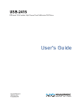
SUMMARY: The AKCO2 systems provide injection and absorption of CO2 gas into a
circulating water system, via solenoid with rate control valve. CO2 is a natural, noncorrosive gas that can be used as a substitute for liquid acid in chemical treatment of
aquatic systems. When dissolved in water it forms weak acid, H2CO3 (carbonic acid), which
can be used to lower pH and raise total alkalinity.
AKCO2 features as follows:
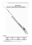
SOLENOID AND RATE CONTROL VALVE: U.L. Listed solenoid, bronze body with
¼” connections are controlled via 120VAC coil relay housed in a vented anodized
aluminum case. Rate control valve has full range adjustment and indicator. Capacity
is 30 SCFH for AKCO2 LOW and 100 SCFH for AKCO2 HIGH.
REGULATOR: AKCO2 LOW uses a U.L. Listed 50 PSI fixed output regulator with a 0
– 4000PSI tank pressure gauge. AKCO2 HIGH uses a U.L. Listed 50 PSI fixed output
heated regulator with a 0 – 4000PSI tank pressure gauge. AKCO2 NR has NO
REGULATOR.
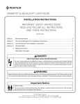
CO2 INJECTOR ASSEMBLY: has a built-in check valve with ½ NPT threaded highdensity porous polyethylene diffuser.
PLUMBING: All fittings are 3/8 Polypropylene Tube fittings, and the tubing is Low
Density Polyethylene with a 120 PSI at 73 degrees F rating.
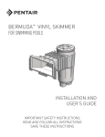
AKCO2 LOW
P/N: 400000100, Rev. B - ASORB-IT OPERATION & INSTALLATION MANUAL
5
AKCO2 HIGH
AK-AUTO
P/N: 400000100, Rev. B - ASORB-IT OPERATION & INSTALLATION MANUAL
6
AKCO2 NR
P/N: 400000100, Rev. B - ASORB-IT OPERATION & INSTALLATION MANUAL
7
1.4
INTRODUCTION
The AKCO2 INSTALLATION AND OPERATION MANUAL explains the procedures for proper
installation and operation of the AKCO2 series CO2 injection systems.
The INSTALLATION portion, introduces the parts of the AKCO2 and the process to
follow when installing the electrical connections for the AKCO2.
The OPERATION portion, describes how to use the AKCO2.
If you have any questions regarding this product, please feel free to call your local
dealer or Pentair Water Commercial Pool and Aquatics™ ("Pentair") directly.
P/N: 400000100, Rev. B - ASORB-IT OPERATION & INSTALLATION MANUAL
8
CHAPTER 2 INSTALLATION
2.1
•
INSTALLATION PREPARATION
Receipt Inspection: Upon receiving an AKCO2 system, check the carton carefully.
Report any damaged items directly to the shipping company. Go through the shipping
list and verify that all items are present. Please contact your local dealer if any
inventoried items are missing or have been damaged. Use care when unpacking
equipment to avoid damage or loss of small parts.
Input Power: 120VAC.
Select INPUT devices: The AKCO2 systems are designed to be used with Pentair
controllers.
2.2
PLUMBING/ELECTRICAL INSTALLATION
Each electrical installation for the AKCO2 can be different. This manual gives the basic
principles to be applied for any specific installation as follows:
•
•
•
•
•
•
•
•
•
•
•
•
•
•
Identify the new and existing equipment to be connected.
Determine the controller supplying on power.
Determine the placement of the controller and mount. (See mounting below)
Determine the AKCO2’s mounting location, and mount.
Locate CO2 cylinder within six feet of controller.
Use plumbing tape on all plumbing fittings and diffuser installation.
Install the diffuser in the return line by drilling and tapping a ½ “ NPT hole in the bottom
of the line. CAUTION! The diffuser needs to be installed downstream of any
equipment since the CO2 produces a pH of around 5.5. Thread the diffuser up into the
½” NPT hole.
Use only 3/8” O.D. Polyethlene pipe from the AKCO2 to the diffuser.
Connect the pressure regulator to the cylinder. The regulator has a fixed 50PSI output.
Use only 3/8” O.D. Polyethlene pipe from the AKCO2 to the regulator.
Connect the control from a normally open relay set for 120VAC operation using 18GA
pigtail. Or hardwire with Relay NO line voltage must be connected to the AKCO2
“BLACK” wire, relay NO neutral must be connected to the AKCO2 “WHITE” wire, and
Relay GND (Ground) must be connected to the AKCO2 “GREEN” wire.
On AKCO2 HIGH connect the regulator heater to 120VAC power.
Connect the supply voltage.
Test the operation of the AKCO2.
WARNING! Be sure to have a licensed electrician perform all electrical wiring. This is
important, as they will be familiar with the electrical codes in the local area.
P/N: 400000100, Rev. B - ASORB-IT OPERATION & INSTALLATION MANUAL
9
2.2.1 ELECTRICAL AND CO2 SPECIFICATIONS
The following electrical specifications in the table below must not be exceeded.
ITEM
DESCRIPTION
LIMIT
Control
Power control form controller
120VAC
AKCO2 HIGH
To Regulator Heater
120VAC
CO2 Pressure
Before regulator (Bottle Pressure)
3000 PSI max
CO2 Pressure
After regulator
50 PSI max
CO2 Flow
AKCO2 LOW and NR flow
0 - 30 SCFH
CO2 Flow
AKCO2 HIGH flow
0 – 100 SCFH
2.3
MOUNTING THE AKCO2
Select a location for mounting the AKCO2, meeting the following recommendations:
At least ten (10) feet from open water.
Supply power must be routed to the AKCO2 in accordance with the applicable codes in
the area; the supplied cord is not code in some areas.
Mount with four bolts.
The environment should be free of chemical fumes and excessive heat. The maximum
room temperature is 110 ºF.
Mount as far as possible from sources of electrical interference.
Since the AKCO2 produces a very low pH the Discharge should be plumbed after all
other equipment just before the return to the pool. The Suction should be plumbed
after the main filter.
P/N: 400000100, Rev. B - ASORB-IT OPERATION & INSTALLATION MANUAL
10
AKCO2 MOUNTING
AK-AUTO MOUNTING
P/N: 400000100, Rev. B - ASORB-IT OPERATION & INSTALLATION MANUAL
11
2.4
FINISHING AND TESTING
Once the AKCO2 system has been installed the following steps are required for final
system finishing and testing.
1. Perform STARTUP procedure.
2. Test system for leaks.
3. Record the feed rate calculated in the STARTUP nearby unit for future use.
4. Test and operate.
P/N: 400000100, Rev. B - ASORB-IT OPERATION & INSTALLATION MANUAL
12
CHAPTER 3 OPERATION
CO2 flow valve
3.1
CONTROLS
3.1.1
CO2 ADJUSTMENT
Pressure: The AKCO2 has a fixed 50 PSI output regulator. If you use an adjustable
regulator or facility supplied CO2, set the output pressure no greater than 50 PSI.
FLOW: The AKCO2 CO2 flow should be adjusted to as low as possible while still
maintaining the desired pH control. A perfectly adjusted and balanced system will have
CO2 feed times of less than 1 minute for systems consisting of 2000 gallons or less and
feed times of 1 to 5 minutes for systems greater than 2000 gallons.
P/N: 400000100, Rev. B - ASORB-IT OPERATION & INSTALLATION MANUAL
13
3.2
AKCO2 STARTUP
To startup an AKCO2 follow to steps below.
1. Start with the AKCO2 control relay in the OFF position, the CO2 cylinder valve
closed, and the CO2 flow valve closed.
2. Open the CO2 cylinder valve and test the CO2 lines for leaks with a soap solution.
3. Manually turn on the control relay and slowly open the CO2 flow valve until the flow
gage reads 5 SCFH for systems consisting of 2000 gallons or less and 20-25
SCFH for systems greater than 2000 gallons.
4. Turn off the control relay. The CO2 flow should stop.
5. Hand check the system water pH. Record value.
6. Turn on the control relay. Note the time. For a LARGE body of water, greater than
2000 gallons, wait 5 minutes and then turn off the AKCO2 control relay. For a
SMALL body of water, less than 2000 gallons, wait 1 minute and then turn off the
AKCO2 control relay..
7. Hand check the system pH. Record the value. See the work sheet below and
calculate the feed rate.
8. If the feed rate is too high redo steps 5 - 7 with the flow valve throttled to a lower
flow. If the feed rate is too low redo step 5 - 7 with the flow valve throttled to a
higher flow.
9. Once feed rate is adjusted set the feed and mixing times in the relay program and
place the relay in automatic. Startup is complete.
AKCO2 STARTUP WORK SHEET
STEP 5
Hand Check pH before CO2 flow valve opened _____________ pH1
STEP 6
CO2 flow ___________________________________________ CFPH
STEP 6
Time Start________ Time Stop ________ Total Time ________ Minutes
STEP 7
Hand Check pH after time test __________________________ pH2
PH Change = pH1 – pH2 = _______________________ pH
Feed Rate = pH Change / Total Time _______________ pH / minute
P/N: 400000100, Rev. B - ASORB-IT OPERATION & INSTALLATION MANUAL
14
3.3
TROUBLE SHOOTING
3.3.1 PH IS NOT DECREASING
1. Check that there is power to the unit and that the CO2 flow gage shows flow when unit is
on.
2. If there is no CO2 flow check to see if the CO2 cylinder is empty and needs replacement.
3. If there is a great system load the current feed rate may not be able to keep up. The
CO2 flow may need to be increased.
3.3.2 PH IS NOT CONTROLLING WELL
1. Feed rate or controller programming is not balanced to water system needs. Perform
the STARTUP again or adjust the controller relay feed and mixing times based on the
feed rate calculated.
IMPORTANT:
IF THERE REMAINS ANY PROBLEMS AFTER READING THE
GUIDES & TROUBLESHOOTING PROCEDURES PLEASE CALL YOUR DEALER
DIRECTLY. BEFORE CALLING PLEASE BE READY WITH THE FOLLOWING ITEMS:
MODEL NUMBER OF THE CONTROLLER
P/N: 400000100, Rev. B - ASORB-IT OPERATION & INSTALLATION MANUAL
15