1
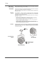
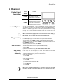
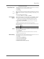
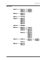
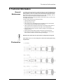
User Manual Edition Notes Edition Notes The COLORado™ 1 VW Tour User Manual Rev. 01d covers the description, safety precautions, installation, programming, operation, and maintenance of the COLORado™ 1 VW Tour. CHAUVET® released this edition of the COLORado™ 1 VW Tour User Manual Rev. 01d in October 2010. Trademarks CHAUVET® is a registered trademark of CHAUVET & Sons Inc. (d/b/a CHAUVET® or Chauvet). The CHAUVET® logo in its entirety including the Chauvet name and the dotted triangle, and all other trademarks on this manual pertaining to services, products, or marketing statements (example: It’s Green Thinking™) are owned or licensed by CHAUVET®. Any other product names, logos, brands, company names, and other trademarks featured or referred to within this document are the property of their respective trademark holders. Copyright Notice CHAUVET® owns the content of this user manual in its entirety, including but not limited to pictures, logos, trademarks, and resources. © Copyright 2010 CHAUVET®. All rights reserved Electronically published by CHAUVET® in the United States of America Manual Usage CHAUVET® authorizes its customers to download and print this manual for professional information purposes only. CHAUVET® expressly prohibits the usage, copy, storage, distribution, modification, or printing of this manual or its content for any other purpose without its written consent. Document Printing For better results, print this document in color, on letter size paper (8.5 x 11 inches), double sided. If using A4 paper (210 x 297 mm), configure your printer to scale the content of this document to A4 paper. Intended Audience Any person in charge of installing, operating, and/or maintaining the COLORado™ 1 VW Tour should read the guide that shipped with it as well as this manual in their entirety before installing, operating, or maintaining this product. Disclaimer CHAUVET® believes that the information contained in this manual is accurate in all respects. However, CHAUVET® assumes no responsibility for any error or omissions in this document. CHAUVET® reserves the right to revise this document and to make changes from time to time in the content hereof without obligation of CHAUVET® to notify any person or company of such revision or changes. This does not constitute in any way a commitment by CHAUVET® to make such changes. CHAUVET® may issue a revision of this manual or a new edition of it to incorporate such changes. CHAUVET® Publications Hot Line If you have any comments about the accuracy of this document or general suggestions regarding how we can improve it, please call us at (800) 762-1084 (US callers) or +1954-929-1115 (international callers). You can download the latest versions of all CHAUVET® products’ manuals from www.chauvetlighting.com. Document Revision The COLORado™ 1 VW Tour User Manual Rev. 01d supersedes all previous versions of this manual. Please discard any older versions of this manual you may have, whether in printed or electronic format, and replace them with this version. Product at a Glance Author Editor Manager PD Manager O. Desmonteix D. Couppe M. Graham F. Sellers Use on Dimmer Outdoor Use Sound Activated DMX Master/Slave Auto Programs Auto-ranging Power Supply Replaceable Fuse User Serviceable Duty Cycle COLORado™ 1 VW Tour User Manual Rev. 01d Table of Contents Table of Contents 1. Before You Begin .............................................................................................................. 1 What is Included .................................................................................................................................. 1 Unpacking Instructions ........................................................................................................................ 1 Typographic Conventions .................................................................................................................... 1 Icons Conventions ............................................................................................................................... 1 Safety Notes ........................................................................................................................................ 2 Expected LED Lifespan ....................................................................................................................... 2 2. Introduction ....................................................................................................................... 3 Product Description ............................................................................................................................. 3 Features ............................................................................................................................................... 3 Additional Features ........................................................................................................................................... 3 Options ............................................................................................................................................................. 3 DMX Channel Summary ...................................................................................................................... 4 Product Overview ................................................................................................................................ 5 3. Setup .................................................................................................................................. 6 AC Power ............................................................................................................................................. 6 AC Plug ............................................................................................................................................................ 6 Power Linking ................................................................................................................................................... 6 Fuse Replacement............................................................................................................................................ 6 DMX Linking ........................................................................................................................................ 7 DMX Modes ...................................................................................................................................................... 7 Master/Slave Connectivity ................................................................................................................................ 7 ID Addressing ...................................................................................................................................... 7 Mounting .............................................................................................................................................. 8 Orientation ........................................................................................................................................................ 8 Rigging ............................................................................................................................................................. 8 4. Operation ........................................................................................................................... 9 Control Panel Description .................................................................................................................... 9 Control Options .................................................................................................................................... 9 Programming ....................................................................................................................................... 9 DMX Personality ............................................................................................................................................... 9 DMX Control Without ID Addressing................................................................................................................. 9 DMX Control With ID Addressing.................................................................................................................... 10 Static Mode ..................................................................................................................................................... 10 Master/Slave ................................................................................................................................................... 10 Dimmer Curves ............................................................................................................................................... 10 Control Panel Lock ......................................................................................................................................... 11 Static Settings Upload .................................................................................................................................... 11 Reset .............................................................................................................................................................. 11 Whites Setting ................................................................................................................................................ 11 STD.2 Notes ...................................................................................................................................... 12 Master Dimmer ............................................................................................................................................... 12 Warm White & Cool White Selection .............................................................................................................. 12 White Macros .................................................................................................................................................. 12 Strobe ............................................................................................................................................................. 12 ID Address Selection ...................................................................................................................................... 12 Menu Map .......................................................................................................................................... 13 DMX Values ....................................................................................................................................... 14 STD.W ............................................................................................................................................................ 14 STD.D ............................................................................................................................................................. 14 STD.1 ............................................................................................................................................................. 14 STD.2 ............................................................................................................................................................. 14 UNO................................................................................................................................................................ 14 COLORado™ 1 VW Tour User Manual Rev. 01d -a- Table of Contents 5. Technical Information ..................................................................................................... 15 General Maintenance ........................................................................................................................ 15 Photometrics ..................................................................................................................................... 15 Troubleshooting Guide ...................................................................................................................... 16 Exploded View................................................................................................................................... 17 Returns Procedure ............................................................................................................................ 18 Claims ............................................................................................................................................... 18 Contact Us ......................................................................................................................................... 18 Technical Specifications .................................................................................................................... 19 -b- COLORado™ 1 VW Tour User Manual Rev. 01d Before You Begin 1. Before You Begin What is Included Unpacking Instructions • One COLORado™ 1 VW Tour • One power input cable with Edison plug (US) • One gel frame holder • One safety cable • One Warranty Card • One Quick Reference Guide Immediately upon receiving this product, carefully unpack it and check the container in which you received it. Make sure that you have received all the parts indicated above and that they are all in good condition. If the material inside the container (this product, and any other accessory included with it) appears damaged from shipping, or if the container shows signs of mishandling, notify the shipper immediately. In addition, retain the container and all the packing material for inspection. See the Claims section in the Technical Information chapter. Typographic Conventions Icons Conventions Convention 1~512 50/60 [10] Claims “COLORado™ UM” <SET> Settings MENU > Settings 1~10 Yes/No ON Icon Meaning A range of values in the text A set of mutually exclusive values in the text A DIP switch to be configured A new term, or a section or chapter in this document The name of another publication or manual A button on the fixture’s control panel A fixture function or a menu option A sequence of menu options A range of menu values from which to choose in a menu A set of two mutually exclusive menu options in a menu A unique value to entered or select in a menu Meaning This icon indicates critical installation, configuration, or operation information. Failure to comply with this information may render the fixture partially or completely inoperative, damage third-party equipment, or cause harm to the user. This icon indicates important installation or configuration information. Failure to comply with this information may prevent the fixture from functioning correctly. This icon indicates useful, although non-critical information. The term “DMX” used throughout this document refers to the USITT DMX512-A transmission protocol. COLORado™ 1 VW Tour User Manual Rev. 01d -1- Before You Begin Safety Notes Please read the following notes carefully because they include important safety information about the installation, usage, and maintenance of this product. It is important to read all these notes before starting to work with this product. There are no user serviceable parts inside this product. Any reference to servicing it you may find from now on in this User Manual will only apply to properly CHAUVET® certified technicians. Do not open the housing or attempt any repairs unless you are one of them. Please refer to all applicable local codes and regulations for the proper installation of this product. Keep this manual for future consultation. If you sell this product to another user, make sure that they also receive this manual. Personal Safety • • • • Avoid direct eye exposure to the light source while the fixture is on. Always disconnect this product from its power source before servicing. Always connect this product to a grounded circuit to avoid the risk of electrocution. Do not touch this product’s housing when operating because it may be very hot. Mounting and Rigging • This product is for indoor use only! To prevent risk of fire or shock, do not expose this product to rain or moisture. Make sure there are no flammable materials close to this product while operating. When hanging this product, always secure it to a fastening device using a safety chain/cable (included). • • Power and Wiring • • • • Operation • • • • Always make sure that you are connecting this product to the proper voltage, as per the specifications in this manual or on the product’s sticker. Never connect this product to a dimmer pack or rheostat. Make sure the product’s housing, or power cable are not cracked, crimped, or damaged. Never disconnect this product by pulling or tugging on the power cable. Do not operate this fixture if you see damage on the housing, lenses, ultraviolet filter, or cables; have the damaged parts replaced by an authorized technician at once. Do not cover the ventilation slots when the fixture is operating to avoid internal overheating. The maximum ambient temperature (Ta) is 104° F (40° C). Do not operate this product at a higher temperature. In case of a serious operating problem, stop using this product immediately! In the unlikely event that your CHAUVET® product may require service, please contact CHAUVET® Technical Support. Expected LED Lifespan -2- LEDs gradually decline in brightness over time, mostly because of heat. Packaged in clusters, LEDs exhibit higher operating temperatures than in ideal, single LED conditions. For this reason, using clustered LEDs at their fullest intensity significantly reduces the LEDs’ lifespan. Under normal conditions, this lifespan can be of 40,000 to 50,000 hours. If extending this lifespan is vital, lower the operational temperature by improving the fixture’s ventilation and reducing the external temperature. In addition, limiting the overall projection intensity may also help to extend the LEDs’ lifespan. COLORado™ 1 VW Tour User Manual Rev. 01d Introduction 2. Introduction Product Description The COLORado™ 1 VW Tour is an indoor variable white wash light based on 42 white LEDs. It consists of a single pod with a double bracket mounting yoke. The AC power comes into the fixture’s housing through a NEUTRIK® powerCON A socket. The power linking uses a NEUTRIK® powerCON B socket. The DMX input and output sockets are of the 3-pin XLR type. The COLORado™ 1 VW Tour uses a display-based control panel for programming functions. • • 1, 2, 3, or 6-channel white LED wash light with ID addressing Operating modes: 1-channel: Dimmer 2-channel: Warm white, cool white 2-channel: Macros, dimmer 3-channel: Warm white, cool white, dimmer 6-channel: Warm white, cool white, dimmer, strobe, macro, ID addressing Color temperature mixing with or without DMX controller Color temperature presets (3,200~5,600 K) Additional Features • • • • • • • Five distinct dimming curves 3-pin DMX input and output connectors Power linking: max 12 units @ 120 V LED display with password protection Gel frame holder (4 mm max thickness) Double-bracket yoke that doubles as floor stand NEUTRIK® powerCON power input and output connectors Options • Optional 15º lenses, P/N: CLENS1542 (30º lenses already installed) Features • • COLORado™ 1 VW Tour User Manual Rev. 01d -3- Introduction DMX Channel Summary -4- STD.1 DMX Channel 1 2 Function Master Dimmer White Macros STD.2 DMX Channel 1 2 3 4 5 6 Function Master Dimmer Warm White Cool White White Macros Strobe ID Address STD.D DMX Channel 1 2 3 Function Master Dimmer Warm White Cool White STD.W DMX Channel 1 2 Function Warm White Cool White UNO DMX Channel 1 Function Static mode COLORado™ 1 VW Tour User Manual Rev. 01d Introduction Product Overview Safety cable passageway Power In Power Out A = 30 mm B = 13 mm DMX In DMX Out Control Panel (Plate removed) COLORado™ 1 VW Tour User Manual Rev. 01d -5- Setup 3. Setup AC Power The COLORado™ 1 VW Tour has an auto-ranging power supply that can work with an input voltage range of 100~240 VAC, 50/60 Hz. Make sure that you are connecting this product to the proper voltage, as per the specifications in this guide, the product’s user manual, or on the product’s sticker. Always connect the COLORado™ 1 VW Tour to a protected circuit with an appropriate electrical ground to avoid the risk of electrocution or fire. To determine the power requirements for the COLORado™ 1 VW Tour see the label affixed to the side of the fixture. Alternatively, you may refer to the corresponding specifications chart in the Technical Information chapter of this manual. The listed current rating indicates the maximum current draw during normal operation. For more information, you may download the “Sizing the Circuit Breakers” document from the CHAUVET® Web site. Never connect the COLORado™ 1 VW Tour to a rheostat (variable resistor) or dimmer circuit, even if the rheostat or dimmer channel serves only as a 0 to 100% switch. AC Plug -6- The COLORado™ 1 VW Tour comes with a power input cord terminated with a NEUTRIK® powerCON A connector on one end an Edison plug on the other end (US market). If the power cord that came with your fixture has no plug or you need to change the Edison plug, use the table below to wire the new plug. Connection Wire (US) Wire (Europe) Screw Color AC Live Black Brown Yellow or Brass AC Neutral White Blue Silver AC Ground Green/Yellow Green/Yellow Green Power Linking The COLORado™ 1 VW Tour supports power linking for up to 12 other COLORado™ 1 VW Tour fixtures at 120 VAC. Each COLORado™ 1 VW Tour has NEUTRIK® powerCON sockets for Power In and Power Out. Although the fixture comes with a power input cord, it comes with no power linking cord. Fuse Replacement The COLORado™ 1 VW Tour fixture has no external fuse that the user can change. However, it does have an internal fuse that only an authorized CHAUVET® technician should change. COLORado™ 1 VW Tour User Manual Rev. 01d Setup DMX Linking You may link any COLORado™ 1 VW Tour fixture to a DMX controller using a standard DMX serial connection. If using other DMX compatible fixtures with a COLORado™ 1 VW Tour fixture, it is possible to control them individually with a single DMX controller. If you are not familiar with the DMX standard, or if you need information about the DMX cables needed to link the COLORado™ 1 VW Tour fixture to a DMX controller, you may download the “DMX Primer” document from the CHAUVET® Web site. DMX Modes The COLORado™ 1 VW Tour uses the standard DMX data connection for its DMX modes, STD.1, STD.2, STD.W, STD.D, and UNO. You will find information about these DMX modes in the Introduction chapter (brief description), the Operation Instructions chapter (configuration details), and the DMX Values section (individual channel values). Master/Slave Connectivity The Master/Slave mode allows a COLORado™ 1 VW Tour fixture to control one or more a COLORado™ 1 VW Tour fixtures of the same type without a DMX controller. The controlling fixture becomes the “master” by being in STATIC mode. The controlled fixtures are the “slaves” and you must set them to “SLAVE” mode from their respective control panels. During the Master/Slave operation, the slave fixtures will operate in unison with the master fixture. The master and slave fixtures link to each other using the standard DMX serial connection. If you are not familiar with the Master/Slave connectivity, you may download the “DMX Primer” document from the CHAUVET® Web site. DO NOT connect a DMX controller to the fixtures operating in Master/Slave mode. Otherwise, the signals from the DMX controller may interfere with the signals from the master unit. The Operation chapter of this manual provides detailed instructions on how to configure the Master and Slave units. ID Addressing The COLORado™ 1 VW Tour uses the ID Addressing feature to increase the number of addressable fixtures in the same DMX universe when in the STD.2 personality. Refer to the Operation chapter in this manual to learn in detail how to configure the COLORado™ 1 VW Tour fixtures when using ID Addressing. If you are not familiar with the various connection methods when using ID Addressing, you may download the “DMX Primer” document from the CHAUVET® Web site. COLORado™ 1 VW Tour User Manual Rev. 01d -7- Setup Mounting Before mounting this fixture, read and follow the safety recommendations indicated in the Safety Notes section (page 2 of this manual). Orientation Always mount this fixture in any safe position while making sure that there is adequate room around it for ventilation, configuration, and maintenance. Make sure to mount this fixture away from any flammable material as indicated in the Safety Notes section. Rigging The COLORado™ 1 VW Tour consists of a sealed housing with a double bracket mounting yoke. It has two DMX signal sockets (DMX In/DMX Out), and two NEUTRIK® powerCON connectors (Power In/Power Out). CHAUVET® recommends following the general guidelines below when mounting the COLORado™ 1 VW Tour. Procedure • When selecting an installation location, consider ease of access to the fixture for operation, programming adjustments, and routine maintenance. • Never mount the fixture in places where rain, high humidity, extreme temperature changes, or restricted ventilation may affect it. • If hanging this fixture, make sure that the location where you are mounting the fixture can support its weight. Please see the Technical Specifications section of this manual for the weight requirement of this fixture. This fixture includes a mounting yoke to which you can attach one or two rigging clamps. You must supply your own “C” or “O” clamps and make sure that they are capable of supporting the weight of this fixture. CHAUVET® recommends using at least two mounting points per fixture. C clamp (not included). Product Mounting Diagram Floor Mounting Secure the safety cable using the passageway on the back of the fixture. Overhead Mounting -8- COLORado™ 1 VW Tour User Manual Rev. 01d Operation 4. Operation Control Panel Description Button Function <MENU> <ENTER> <UP> <DOWN> Control Options Exits from the current menu or function Enables the currently displayed menu or sets the currently selected value in to the current function Navigates upwards through the menu list and increases the numeric value when in a function Navigates downwards through the menu list and decreases the numeric value when in a function You can set the COLORado™ 1 VW Tour start address in the 001~512 DMX range. This allows for the control of up to 85 fixtures in the 6-channel STD.2 personality. In addition, the ID address system allows you to assign up to 66 fixtures within the same DMX address, thus multiplying the number of fixtures you can control within a single universe. You can access the fixture’s ID address system from channel 6 when in the STD.2 personality. When programming live performances as well as cues that need to trigger on demand or on a time line, program no more than 10 fixtures on ID addressing per DMX channel. This is to remain within a one-second execution time. Programming Carry out all the programming procedures indicated below from the control panel. Refer to the Menu Map on page 13 to learn how the menu options relate to each other. To go to an option, press <MENU> repeatedly until the option shows on the display. To select an option value, press <UP> or <DOWN> until you see the desired value and press <ENTER> to accept it. To exit to the previous menu level, press <MENU>. DMX Personality This setting allows the user to choose a particular DMX personality. 1) Go to PERS. 2) Select the desired personality (STD.1, STD.2, STD.W, STD.D, or UNO). DMX Control Without ID Addressing In this mode, each unit will respond to a unique starting address from the DMX controller. All units with the same starting address will respond in unison. 1) Select the STD.2 personality as shown in DMX Personality. 2) Set the running mode: a) Go to RUN. b) Select DMX. 3) Set the starting address: a) Go to DMX. b) Select the starting address (001~512). 4) Deactivate ID Addressing on each fixture: a) Go to SET > ID. b) Select OFF. Make sure to deactivate ID Addressing in each fixture when using the STD.1 personality. Otherwise, unintended results may occur if channel 6 is not set to “0”. Continues on the next page COLORado™ 1 VW Tour User Manual Rev. 01d -9- Operation Continued from previous page DMX Control With ID Addressing In this mode, the fixtures with the same DMX starting address will respond to the DMX controller based on the fixture’s individual ID address setting. If the user selects ID address “0”, all the fixtures with the same DMX address will respond in unison. Otherwise, each fixture will follow the control for its particular ID address. 1) Repeat steps 1, 2, and 3 from DMX Control Without ID Addressing. 2) Activate ID Addressing in each fixture: a) Go to SET > ID. b) Select ON. 3) Select an ID address for each fixture: a) Go to ID. b) Select an ID (01~66) Static Mode The Static mode allows for permanent white color mixing without a DMX controller. 1) Go to STAT. 2) Select the desired white range (Warm or Cool). 3) Select the desired white range value (0~255). 4) Repeat for the other white range. 5) Select Strob. 6) Select the desired frequency (0~20). Master/Slave The Master/Slave mode allows a group of COLORado™ 1 VW Tour fixtures (the slaves) to replicate what another COLORado™ 1 VW Tour fixture (the master) is doing, without a DMX controller. 1) Set the Master Unit: a) Set the running mode to DMX as explained in “DMX Control Without ID Addressing”. b) Select a static setting as explained in “Static Mode”. 2) Set the slave units: a) Go to RUN. b) Select SLAV. Dimmer Curves • The fixture that is set to run in STATIC mode automatically becomes the Master. • Do not connect a DMX controller to the master or slave fixtures. This setting determines how the output of the COLORado™ 1 VW Tour follows the position of the Dimmer fader, as well as the Warm White and Cool White faders. 1) Go to SET. 2) Select Dim. 3) Select a dimmer curve (Off, Dim1, Dim2, Dim3, or Dim4). Setting OFF Dim1 Dim2 Dim3 Dim4 Description The output is proportional to the faders’ position (linear) The output is not proportional (fastest) The output is not proportional (fast) The output is not proportional (slow) The output is not proportional (slowest) Continues on the next page -10- COLORado™ 1 VW Tour User Manual Rev. 01d Operation Continued from previous page Control Panel Lock This setting allows the user to activate or disable the control panel lock, which keeps non-authorized personnel from changing the fixture’s settings. 1) Go to KEY. 2) Select On/ Off. When the control panel lock is active, the fixture will prompt the user to enter the password after 30 seconds of control panel inactivity or after turning on the fixture. After being prompted to enter the password: 1) Press <UP>, <DOWN>, <UP>, <DOWN>, and <ENTER> Static Settings Upload This option allows the user to copy the static settings of one COLORado™ 1 VW Tour fixture onto other COLORado™ 1 VW Tour fixtures by using the Master/Slave method. 1) Configure and connect the fixtures in a Master/Slave arrangement, where the master unit has the custom programs you want to transfer onto the slave units. 2) At the master unit, go to SET > UPLD. 3) When prompted, enter the master access password as shown in Control Panel Lock. 4) Wait for the upload process to finish before disconnecting the fixtures. During and after the upload, the master and slave units will visually indicate the status of the process, as follows: Color LEDs Off Cool White Reset Meaning The upload process is running The upload finished successfully This setting allows the user to reset the COLORado™ 1 VW Tour fixture to its default values, including the custom programs. 1) Go to SET> REST. 2) When prompted, enter the master access password as shown in Control Panel Lock. 3) Wait for the reset process to finish. Whites Setting This setting allows the user to edit the temperature of the six white macros used in the macros channel. The six pre-set white macros are configurable. 1) Go to CAL1. 2) Select a white macro (WT.01~05). 3) Select a white range (Warm or Cool). 4) Select a white range value (0~255). 5) Repeat for the other white range. 6) Repeat for the other white macros (WT.01~05). COLORado™ 1 VW Tour User Manual Rev. 01d -11- Operation STD.2 Notes Master Dimmer Warm White & Cool White Selection White Macros Strobe These notes intent to clarify the way the STD.2 DMX personality works. • Channel 1 controls the intensity of the currently projected color. • When the slider is at the highest position (255) the intensity of the output is at its maximum. • Channels 2 and 3 control the intensity ratio of the Warm White and Cool White LEDs respectively. • When each of these sliders is at the highest position (255), the intensity of the corresponding color is at its maximum. • You can combine channels 2 and 3 to create over 60,000 shades of white. • Channel 4 selects the required White Macro. • Channel 4 has priority over channels 2 and 3. • Channel 1 controls the intensity of the Color Macro. • • • ID Address Selection -12- Channel 5 controls the strobe frequency (not the intensity) of channels 2~4. Channel 5 strobes channels 2 and 3 when not running macros, allowing the individual faders (Warm White and Cool White) as well as channel 1 (Dimmer) to control the output intensity. Channel 5 strobes channel 4 when running macros, allowing channel 4 to select the white macro and channel 1 to control the output intensity • Channel 6 selects the target ID address. • Each independent DMX address may have up to 66 independent ID addresses. • An ID address of 0 will activate all ID address locations. COLORado™ 1 VW Tour User Manual Rev. 01d Operation Menu Map COLORado™ 1 VW Tour User Manual Rev. 01d -13- Operation DMX Values STD.W Channel Function 1 2 STD.D Channel Function 1 2 3 STD.1 STD.2 1 Dimmer 2 White Macros Channel Function 1 2 3 Dimmer Warm White Cool White 4 White Macros 5 Strobe ID Address Channel Function 1 -14- Dimmer Warm White Cool White Channel Function 6 UNO Warm White Cool White Dimmer (STAT) Value Percent/Setting 000 255 0~100% 000 255 0~100% Value Percent/Setting 000 255 0~100% 000 255 0~100% 000 255 0~100% Value 000 255 000 010 011 050 051 080 081 110 111 140 141 255 Value 000 255 000 255 000 255 000 010 011 050 051 080 081 110 111 140 141 255 000 009 010 255 Percent/Setting 0~100% No function Studio white: 3,200 K Studio white: 3,400 K Studio white: 4,500 K Studio white: 4,900 K Studio white: 5,600 K Percent/Setting 0~100% 0~100% 0~100% No function Studio white: 3,200 K Studio white: 3,400 K Studio white: 4,500 K Studio white: 4,900 K Studio white: 5,600 K No function 0~20 Hz Value Setting Value 000 009 010 019 020 029 030 039 040 049 050 059 060 069 070 079 080 089 090 099 100 109 110 119 120 129 130 139 140 149 150 159 160 169 170 179 180 189 190 199 200 209 210 211 All IDs ID 1 ID 2 ID 3 ID 4 ID 5 ID 6 ID 7 ID 8 ID 9 ID 10 ID 11 ID 12 ID 13 ID 14 ID 15 ID 16 ID 17 ID 18 ID 19 ID 20 ID 21 ID 22 212 213 214 215 216 217 218 219 220 221 222 223 224 225 226 227 228 229 230 231 232 233 234 Value Setting ID 23 ID 24 ID 25 ID 26 ID 27 ID 28 ID 29 ID 30 ID 31 ID 32 ID 33 ID 34 ID 35 ID 36 ID 37 ID 38 ID 39 ID 40 ID 41 ID 42 ID 43 ID 44 ID 45 Value 235 236 237 238 239 240 241 242 243 244 245 246 247 248 249 250 251 252 253 254 255 Setting ID 46 ID 47 ID 48 ID 49 ID 50 ID 51 ID 52 ID 53 ID 54 ID 55 ID 56 ID 57 ID 58 ID 59 ID 60 ID 61 ID 62 ID 63 ID 64 ID 65 ID 66 Percent/Setting 000 255 0~100% COLORado™ 1 VW Tour User Manual Rev. 01d Technical Information 5. Technical Information General Maintenance To maintain optimum performance and minimize wear, the user should clean the light fixtures frequently. Usage and environment are contributing factors in determining the cleaning frequency. As a rule, the user should clean the fixtures at least twice a month. Dust build up reduces light output performance and can cause overheating. This can lead to reduced light source life and increased mechanical wear. CHAUVET® recommends cleaning the fixture’s external optics with a soft cloth using normal glass cleaning fluid. To clean a fixture, follow the recommendations below: • Unplug the fixture from power. • Wait until the fixture is cold. • Use a vacuum (or dry compressed air) and a soft brush to remove dust collected on the external vents and reachable internal components. • Clean all external optics and glass surfaces with a mild solution of glass cleaner or isopropyl alcohol, and a soft, lint free cotton cloth or a lens cleaning tissue. • Apply the solution directly to the cloth or tissue and drag any dirt and grime to the outside of the lens. • Gently polish the external glass surfaces until they are free of haze and lint. • When cleaning units with a movable mirror, you should keep the contact with the mirror surface to a minimum to avoid scratching or damaging it. Always dry the external optics and glass surfaces carefully after cleaning them. If the fixture has one or more cooling fans, refrain from spinning them using compressed air. Photometrics COLORado™ 1 VW Tour User Manual Rev. 01d -15- Technical Information Troubleshooting Guide Symptom General low light intensity A single white LED does not illuminate A group of white LEDs does not illuminate None of the LEDs are illuminating Breaker/Fuse keeps blowing Fixture does not power up Fixture does not respond to DMX Cause(s) Action(s) • Dirty lens assembly • Clean the fixture regularly • Misaligned lens assembly • Install lens assembly properly • Faulty LED • Replace the LED board • Faulty LED board • Replace the LED board • Faulty LED • Replace the LED board • Faulty LED board • Replace the LED board • Faulty LED driver • Replace the LED driver board • Faulty LED PCB • Replace the LED board • Faulty LED Driver PCB • Replace the LED driver board • Faulty main PCB • Replace the Display / Main board • Excessive circuit load • Check total load placed on the electrical circuit • Short circuit along the power wires • Check for a short in the electrical wiring • No power • Check for power on power outlet • Loose or damaged power cord • Check power cord • Blown internal fuse • Replace internal fuse • Faulty internal power supply • Replace internal power supply • Wrong DMX addressing • Check Control Panel and unit addressing • Damaged DMX cables • Check DMX cables • Wrong polarity on the controller • Check polarity switch settings on the controller • Loose DMX cables • Check cable connections • Faulty DMX interface • Replace Main PCB • Faulty Main PCB • Replace Main PCB • Non DMX cables • Use only DMX compatible cables • Bouncing signals • Install terminator as suggested • Long cable / low level signal • Install an optically coupled DMX splitter right after fixture with strong signal • Too many fixtures • Install an optically coupled DMX splitter after unit #32 • Interference from AC wires • Keep DMX cables separated from power cables or black lights DMX signal problems If you still experience technical problems after trying the above solutions, contact CHAUVET® Technical Support. -16- COLORado™ 1 VW Tour User Manual Rev. 01d Technical Information Exploded View Item 1 2 3 4 5 6 7 8 9 10 11 Description Front cover Rubber seal Front tempered glass Lens holder 15º lens LED board Heat sink Power supply Driver board Power connection board Display / Main board COLORado™ 1 VW Tour User Manual Rev. 01d Item 12 13 14 15 16 17 18 19 20 21 22 Description Button Module Display protection plate Button seal Casing Adjusting stainless steel knob NEUTRIK® PowerCON B connector NEUTRIK® PowerCON A connector 3-pin DMX In socket 3-pin DMX Out socket Main support Secondary support -17- Technical Information Returns Procedure The user must send the merchandise prepaid, in the original box, and with its original packing and accessories. CHAUVET® will not issue call tags. Call CHAUVET® and request a Return Merchandise Authorization Number (RMA #) before shipping the fixture. Be prepared to provide the model number, serial number, and a brief description of the cause for the return. The user must clearly label the package with a Return Merchandise Authorization Number (RMA #). CHAUVET® will refuse any product returned without an RMA #. DO NOT write the RMA # directly on the box. Instead, write it on a properly affixed label. Once you receive the RMA #, please include the following information on a piece of paper inside the box: • • • • • Your name Your address Your phone number The RMA # A brief description of the problem Be sure to pack the fixture properly. Any shipping damage resulting from inadequate packaging will be the customer’s responsibility. As a suggestion, proper UPS packing or double-boxing is always a safe method to use. CHAUVET® reserves the right to use its own discretion to repair or replace returned product(s). Claims The carrier is responsible for any damage incurred during shipping to this product or any part that shipped with it. Therefore, if the received merchandise appears to have damages caused during shipping, the customer must submit the damage report and any related claims with the carrier, not CHAUVET®. The customer must submit the report upon reception of the damaged merchandise. Failure to do so in a timely manner may invalidate the customer’s claim with the carrier. For other issues such as missing components or parts, damage not related to shipping, or concealed damage, the customer must make claims to CHAUVET® within seven (7) days of receiving the merchandise. Contact Us World Headquarters General Information CHAUVET® 5200 NW 108th Avenue Sunrise, FL 33351 Voice: (954) 929-1115 Fax: (954) 929-5560 Toll free: (800) 762-1084 Technical Support Voice: (954) 929-1115 (Press 4) Fax: (954) 756-8015 World Wide Web www.chauvetlighting.com -18- COLORado™ 1 VW Tour User Manual Rev. 01d Technical Information Technical Specifications Dimensions and Weight Length 11.4 in (290 mm) Width 9.6 in (245 mm) Height 8.0 in (205 mm) Weight 10.6 lbs (4.8 kg) Note: Dimensions in inches rounded to the nearest decimal digit. Power Power Supply Type Switching (internal) Range 100~240 V, 50/60 Hz Voltage Selection Auto-ranging Parameter Consumption Inrush current Power linking 120 V, 60 Hz 50.4 W (0.7 A) 0.2 A 12 230 V, 50 Hz 50.7 W (0.4 A) 0.4 A 24 Power I/O Connectors Cord plug Cord length Input NEUTRIK® powerCON A Edison 60 in (1,524 mm) Output NEUTRIK® powerCON B N/A N/A Type LED Power 1W Lifespan 50,000 hours Color Warm white Cool white Quantity 24 18 Current 250 mA 250 mA Parameter Illuminance @ 5 m Beam angle Field angle Standard 30º Optics 204 lx 24.8º 60.2 Optional 15º Optics 656 lx 17.4º 32.4º Maximum External Temp. 104° F (40° C) Cooling System Convection I/O Connectors 3-pin XLR Connector Type Sockets COLORado™ 1 VW Tour COLORADO1VWTOUR Optional 15º Optics CLENS1542 Light Source Photo Optic Thermal DMX Ordering COLORado™ 1 VW Tour User Manual Rev. 01d Channel Range 1, 2, 3, and 6 -19- CHAUVET® 5200 NW 108th Avenue Sunrise, FL 33351 (USA) (800) 762-1084 – (954) 929-1115 FAX (954) 929-5560 www.chauvetlighting.com COLORado™ 1 VW Tour User Manual Rev. 01d October 2010