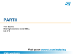
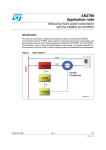
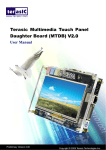
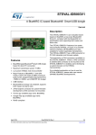
1
UM0746
User manual
Energy meter demonstration kit
based on the STPMC1 and STPMS1
Introduction
The STEVAL-IPE010V1 demonstration board is designed to provide the user with a readyto-use energy meter application for the STPMC1 device, while the STEVAL-IPE011V1 is a
demonstration board for its companion chip STPMS1.
The package contains a STEVAL-IPE010V1 motherboard and three STEVAL-IPE011V1
daughterboards. Additional daughterboards can be ordered if required.
The demonstration board can be used in two ways:
Note:
April 2010
■
For demonstration purposes, by connecting the demonstration platform to an AC power
source, and setting the parameters through the GUI (graphical user interface) and the
parallel hardware programmer/reader.
■
For user application evaluation and development.
The boards do not come programmed or calibrated.
Figure 1.
STEVAL-IPE010V1 motherboard
Figure 2.
STEVAL-IPE011V1 daughterboard
Doc ID 15971 Rev 1
1/10
www.st.com
Contents
UM0746
Contents
1
2
Safety rules . . . . . . . . . . . . . . . . . . . . . . . . . . . . . . . . . . . . . . . . . . . . . . . . 3
1.1
Operating conditions . . . . . . . . . . . . . . . . . . . . . . . . . . . . . . . . . . . . . . . . . 3
1.2
Features . . . . . . . . . . . . . . . . . . . . . . . . . . . . . . . . . . . . . . . . . . . . . . . . . . . 3
1.3
References . . . . . . . . . . . . . . . . . . . . . . . . . . . . . . . . . . . . . . . . . . . . . . . . . 4
1.4
Getting technical support . . . . . . . . . . . . . . . . . . . . . . . . . . . . . . . . . . . . . . 4
STEVAL-IPE010V1 components . . . . . . . . . . . . . . . . . . . . . . . . . . . . . . . . 5
2.1
Package contents . . . . . . . . . . . . . . . . . . . . . . . . . . . . . . . . . . . . . . . . . . . . 5
2.2
STEVAL-IPE010V1 . . . . . . . . . . . . . . . . . . . . . . . . . . . . . . . . . . . . . . . . . . 5
2.3
STEVAL-IPE011V1 . . . . . . . . . . . . . . . . . . . . . . . . . . . . . . . . . . . . . . . . . . 6
2.3.1
3
4
2/10
Jumpers settings . . . . . . . . . . . . . . . . . . . . . . . . . . . . . . . . . . . . . . . . . . . 6
Getting started . . . . . . . . . . . . . . . . . . . . . . . . . . . . . . . . . . . . . . . . . . . . . . 7
3.1
Board assembly . . . . . . . . . . . . . . . . . . . . . . . . . . . . . . . . . . . . . . . . . . . . . 7
3.2
Board connection . . . . . . . . . . . . . . . . . . . . . . . . . . . . . . . . . . . . . . . . . . . . 8
Revision history . . . . . . . . . . . . . . . . . . . . . . . . . . . . . . . . . . . . . . . . . . . . 9
Doc ID 15971 Rev 1
UM0746
1
Safety rules
Safety rules
This board can be connected to mains voltage (220 V/110 V). In the case of improper use,
faulty installation or malfunction, there is a danger of serious personal injury and damage to
property. All operations such as transport, installation and commissioning, as well as
maintenance, should only be carried out by skilled technical personnel (applicable accident
prevention rules must be observed).
Due to the risk of death when using this prototype on mains voltage (220 V/110 V), only
skilled technical personnel who are familiar with the installation, mounting, commissioning
and operating of power electronic systems, and have the relevant qualifications required to
perform these functions, may use this prototype.
1.1
Operating conditions
Table 1.
1.2
Operating conditions
Condition
Value
Unit
VNOM
230
VRMS
INOM
CT: INOM = 1
ARMS
IMAX
CT: IMAX = 30
ARMS
fLIN
50 / 60 ± 10%
Hz
TOP
- 40 / + 85
°C
Features
●
Modularity
●
Programmability
●
Supports:
●
–
3-phase, 4-wire RSTN, 4-system RSTN (tamper); extra module is needed
–
3-phase, 4-wire RSTN, 3-system RST
–
3-phase, 3-wire RST_, 3-system RST_ (tamper)
–
3-phase, 3-wire RST_, 2-system R_T_ (Aron)
–
2-phase, 3-wire _STN, 2-system _ST_ (America)
–
1-phase, 2-wire __TN, 2-system _ST_ (tamper)
–
1-phase, 2-wire __TN, 1-system __T_.
4 LEDs showing:
–
Power
–
No load condition
–
Tamper detection
–
Reverse current direction
–
Embedded capacitive power supply
–
Isolation of current channel
Doc ID 15971 Rev 1
3/10
Safety rules
1.3
UM0746
References
This document describes how to use and set up a basic test session with a GUI. Additional
information can be found in the following documents:
1.4
●
STPMC1 datasheet
●
STPMS1 datasheet
●
STMicroelectronics application notes
●
Schematic diagrams
Getting technical support
Technical assistance is available without charge to all customers. For technical assistance,
documentation and information on product upgrades and services, please refer to your local
ST distributor/office.
STmicroelectronics offers its customers a free technical support service with online support
at www.st.com. Before contacting us, we advise you to confirm that you are using the latest
version of the software/firmware. Upgrades are available without charge at
http://www.st.com/metering.
4/10
Doc ID 15971 Rev 1
UM0746
STEVAL-IPE010V1 components
2
STEVAL-IPE010V1 components
2.1
Package contents
The package contains:
2.2
a)
1 STEVAL-IPE010V1 motherboard
b)
3 STEVAL-IPE011V1 daughterboard
c)
1 parallel programmer/reader
d)
Promotional CD
STEVAL-IPE010V1
This is the motherboard which can accept up to 5 daughterboards. An STPMC1 is mounted
on the module and 4 LEDs indicate the status of the system.
The motherboard can be connected to a PC using the parallel programmer/reader through
the P1 connector.
The board can be supplied from an external DC source (3.3 to 5 V) through the W34
connector.
Test points available are:
●
LED
●
MOP, MON (stepper counter display connector)
●
GND
●
CLK
●
DAR, DAS, DAT, DAN, DAH
For 3-phase 4-wire/3-wire systems only three daughterboards are needed for a complete
measurement system.
Table 2.
P1 connector pin description
Pin
Pin name
1
VOTP
2
---
3
GND
4
SDA-TD
5
SCS
6
SCL-NLC
7
---
8
SYN-NP
9
---
10
VCC
Functional description
Power supply input of +15.0 V during permanent write to OTP cells.
Not connected.
Signal reference level 0 V and power supply return.
SPI interface data.
SPI interface enable.
SPI interface clock.
Not connected.
SPI interface signal.
Not connected.
Power out of +3.3 or 5 V.
Doc ID 15971 Rev 1
5/10
STEVAL-IPE010V1 components
2.3
UM0746
STEVAL-IPE011V1
This is the daughterboard. Each module serves one single phase, converting the voltage
and current information, multiplexing them and sending the stream to the STPMC1.
Each of the boards must be connected to the voltage source of the relative phase and to the
load.
Test points available are:
●
GND
●
VCC (stepper counter display connector)
●
CLK
●
DAT
●
VREG
●
F, N
The STEVAL-IPE011V1 should be plugged into the motherboard using the connector on the
edge of the board.
Voltage inputs are pin F (hot wire) and N (neutral wire).
Current input (load wire) should be passed through the current transformer placed on the
non-component side of the module.
2.3.1
Jumpers settings
The on-board jumpers JP1 and JP2 allow the setting of the STPMS1 device according to
Table 3 and Table 4 below.
Table 3.
JP1
MS0
1
VCC
ampl = 32
2
NCLK
Reserved
3
GND
ampl = 8
4
CLK
Reserved
Table 4.
6/10
Modes of operation
Description
Changing of band-gap voltage reference
JP2
MS1
Description
1
VCC
TC = 190 ppm/°C
2
NCLK
TC = 125 ppm/°C
3
GND
TC = 100 ppm/°C
4
CLK
TC = 170 ppm/°C
Doc ID 15971 Rev 1
UM0746
Getting started
3
Getting started
3.1
Board assembly
Assemble the board as illustrated in the figure below.
Figure 3.
STEVAL-IPE010V1 assembly
Doc ID 15971 Rev 1
7/10
Getting started
3.2
UM0746
Board connection
Plug in the daughterboard as shown in the figure below.
Figure 4.
STEVAL-IPE010V1 assembly
Use the connectors DAR, DAS, DAT, DAN (optional for 4-wire with tamper systems) as
shown in the figure below.
Figure 5.
8/10
STEVAL-IPE010V1 assembly
Doc ID 15971 Rev 1
UM0746
Revision history
4
Revision history
Table 5.
Document revision history
Date
Revision
06-Mar-2010
1
Changes
Initial release.
Doc ID 15971 Rev 1
9/10
UM0746
Please Read Carefully:
Information in this document is provided solely in connection with ST products. STMicroelectronics NV and its subsidiaries (“ST”) reserve the
right to make changes, corrections, modifications or improvements, to this document, and the products and services described herein at any
time, without notice.
All ST products are sold pursuant to ST’s terms and conditions of sale.
Purchasers are solely responsible for the choice, selection and use of the ST products and services described herein, and ST assumes no
liability whatsoever relating to the choice, selection or use of the ST products and services described herein.
No license, express or implied, by estoppel or otherwise, to any intellectual property rights is granted under this document. If any part of this
document refers to any third party products or services it shall not be deemed a license grant by ST for the use of such third party products
or services, or any intellectual property contained therein or considered as a warranty covering the use in any manner whatsoever of such
third party products or services or any intellectual property contained therein.
UNLESS OTHERWISE SET FORTH IN ST’S TERMS AND CONDITIONS OF SALE ST DISCLAIMS ANY EXPRESS OR IMPLIED
WARRANTY WITH RESPECT TO THE USE AND/OR SALE OF ST PRODUCTS INCLUDING WITHOUT LIMITATION IMPLIED
WARRANTIES OF MERCHANTABILITY, FITNESS FOR A PARTICULAR PURPOSE (AND THEIR EQUIVALENTS UNDER THE LAWS
OF ANY JURISDICTION), OR INFRINGEMENT OF ANY PATENT, COPYRIGHT OR OTHER INTELLECTUAL PROPERTY RIGHT.
UNLESS EXPRESSLY APPROVED IN WRITING BY AN AUTHORIZED ST REPRESENTATIVE, ST PRODUCTS ARE NOT
RECOMMENDED, AUTHORIZED OR WARRANTED FOR USE IN MILITARY, AIR CRAFT, SPACE, LIFE SAVING, OR LIFE SUSTAINING
APPLICATIONS, NOR IN PRODUCTS OR SYSTEMS WHERE FAILURE OR MALFUNCTION MAY RESULT IN PERSONAL INJURY,
DEATH, OR SEVERE PROPERTY OR ENVIRONMENTAL DAMAGE. ST PRODUCTS WHICH ARE NOT SPECIFIED AS "AUTOMOTIVE
GRADE" MAY ONLY BE USED IN AUTOMOTIVE APPLICATIONS AT USER’S OWN RISK.
Resale of ST products with provisions different from the statements and/or technical features set forth in this document shall immediately void
any warranty granted by ST for the ST product or service described herein and shall not create or extend in any manner whatsoever, any
liability of ST.
ST and the ST logo are trademarks or registered trademarks of ST in various countries.
Information in this document supersedes and replaces all information previously supplied.
The ST logo is a registered trademark of STMicroelectronics. All other names are the property of their respective owners.
© 2010 STMicroelectronics - All rights reserved
STMicroelectronics group of companies
Australia - Belgium - Brazil - Canada - China - Czech Republic - Finland - France - Germany - Hong Kong - India - Israel - Italy - Japan Malaysia - Malta - Morocco - Philippines - Singapore - Spain - Sweden - Switzerland - United Kingdom - United States of America
www.st.com
10/10
Doc ID 15971 Rev 1