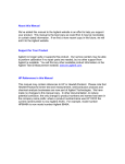
1
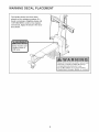
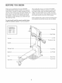
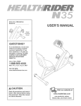
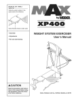
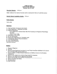
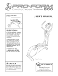
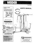
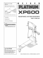
Model No. 831.153992
Serial No.
®
Write the seriaU number in the
space above for future reference,
Serial Number Decal (under seat)
• Assembly
RESISTANCE SYSTEM EXERCISER
User's Manual
• Adjustments
• Part List and Drawing
_CAUTmON
Read all precautions and instruc_
tions in this manuaJ before
using this equipment. Save this
manual for future reference.
Sears,
Roebuck
and Co., Roffman
Estates,
IL 60179
TABLE OF CONTENTS
WARNING DECAL PLACEMENT .............................................................
HMPORTANT PRECAUTHONS ................................................................
BEFORE YOU BEGIN ......................................................................
ASSEMBLY ...............................................................................
UPPER CABLE ADJUSTMENT
..............................................................
ADJUSTMENTS ..........................................................................
CABLE DHAGRAM .........................................................................
TROUBLESHOOTHNG .....................................................................
EXERCISE GUiDELiNES
..................................................................
ORDERING REPLACEMENT PARTS ..................................................
FULL ONE-YEAR WARRANTY
......................................................
3
4
5
6
14
15
18
19
20
Back Cover
Back Cover
Note: A PART iDENTiFiCATiON CHART and a PART LiST/EXPLODED DRAVVHNGare attached in the center of
this manual, Remove the PART iDENTiFiCATiON CHART and PART LiST/EXPLODED DRAWING before beginning assembly,
WARNING DECAL PLACEMENT
:eep hands and
ngers clear of
_s area.
Misuse of this product may resuHtin serious injury.
Read user's manuaNand foNHowaNm
warnings
and operating instructions prior to use.
Do not allow children on or around machine.
• RepHacemabem
if damaged, iRHegibHe,
or removed.
3
iMPORTANT
AWARN!
PRECAUTIONS
NG: Toreduce
thedskofserious
inju_y_
read
thefo,ow_ng
important
precautions
before using the resistance
system.
1.
Read all instructions in this manual before
using the resistance system. Use the resistance system only as described in this manual.
2.
it is the responsibility
of the owner to ensure
that all users of the resistance system are
adequateJy informed of aJl precautions.
3.
4.
11. The crossbar on the top frame is not
desig ned to be used for puHoup exercises.
Do not hang on the crossbar.
The resistance system is intended for home
use only. Do not use the resistance system in
any commercial, rental, or institutional setting.
12. The resistance system
used with the included
use the resistance
type of resistance.
Use the resistance system only on a level
surface. Cover the fJoor beneath the resistance system
5.
on the high cables only while sitting on the
bench, with the seat in one of the three positions closest to the upright base, or while
standing on the base pJate.
to protect the ricer,
Keep children
the resistance
7.
Keep hands and feet away from moving parts.
8.
Always wear athletic shoes for foot protection while exercising.
9.
The resistance system is designed to support a maximum user weight of 300 pounds.
system
with any other
t 3. AJways disconnect the lat bar from the high
cables when performing an exercise that
does not require it.
Make sure that aH parts are properly tightened each time the resistance system is
used. Replace any worn parts immediately.
6.
is designed to be
resistance. Do not
14. Make su re the storage knob is in place and
fuity tightened each time the resistance system is used.
under 12 and pets away from
system at aH times.
15. Make sure that the cables remain on the pulleys at all times, if the cables bind as you are
exercising, stop immediateJy and make sure
that the cables are on the pulleys.
16. Do not pull on the cabJes while the resistance level is being adiusted.
17. if you feel pain or dizziness while exercising,
stop immediateJy and begin cooling down.
10. Pull on the lower cable only whiJe sitting on
the bench or standing on the base plate. Pull
_]_WARNING: Before
beginning
thisoranyexercise
program,
eonsu,
yo_,r
physician.
This
is especially important for persons over the age of 35 or persons with pre-existing health problems.
Read aH instructions before using. Sears assumes no responsibility
for personal injury or property
damage sustained by or through the use of this product.
4
BEFORE YOU BFGmN
Thank you for selecting the innovative WELDER®
PLATINUM XP600 resistance system, The resistance
system offers a selection of stations designed to develop every major muscle group of the body, Whether your
goal is to tone your body, build dramatic muscle size
and strength, or improve your cardiovascular system,
the resistance system will help you to achieve the spe°
cific results you want,
after reading this manual, call 1-800-4-MYoHOME ®
(1 °800°469°4663), To help us assist you, please note
the product model number and serial number before
calling, The model number is 831,153992, The serial
number can be found on a decal attached to the resist°
ance system (see the front cover of this manual),
Before reading further, please review the drawing below
and familiarize yourself with the parts that are labeled,
For your benefit, read this manuaJ carefully before
using the resistance system, if you have questions
ASSEMBLED
DiMENSiONS:
Height:
Width:
82 in,
66 in,
Depth:
80 in,
Crossbar
High Pulley
Console
Lat Bar
Bar
Upright
Storage Knob
Foot Hate
Backrest
Low Pulley
Seat
Base Hate
Seat Knob
Leg Lever
MakeThings
Tighten all parts as you assemble them, unless
instructed to do otherwise.
Easier for Yourself
This manual is designed to ensure that the resistance system can be assembUed suceessfuUiy by
most peopb, However, it is important to realize
that the versatile resistance system has many
parts and that the assembly process will take
time, Most people find that by setting aside plenty
of time. assembly wiUigo smoothly.
, As you assemble the resistance system, make
sure all parts are oriented as shown in the drawings,
The included
Allen wrenches
ii--
the following tools (not included}
for assembly:
Two adjustable
Before beginning assembly, carefully read the
following information and instructions:
[i_and
are required
wrenches
One rubber mallet
One standard
Assembly requires two persons,
Place all parts in a cleared area and remove the
packing materials, Do not dispose of the packing
materials until assembly is completed,
screwdriver
• One Philtips screwdriver
_._
_C__)
Lubricant, such as grease or petroleum
and soapy water.
• For help identifying small parts, use the PART
IDENTIFICATION CHART. Note: Some small
jelly,
Assembly wiii be more convenient if you have a
socket set, a set of open-end or closed-end
wrenches, or a set of ratchet wrenches,
parts may have been pre-attached for shipping, if
a part is not in the parts bag, check to see if it
has been pro-attached,
Before beginning assembly, make sure that
you have read and understand the informa,
tion in the box above.
71
73
Attach a Wheel (21) to the Base (1) with an MIO
x 108mm Button Bolt (90), three MIO Washers
(73), and an MIO Nylon Locknut (71). Do not
overtighten the Locknut; the Wheel must be
able to turn easily.
73
21
90
103
Attach the other Wheel (21} to the Base (!} in
the same manner.
103 _-_j,
Attach two Plastic Feet (19) and two Large Plastic
Feet (20) to the Base (1) with four M4 x 16mm
Screws (103).
6
2.
Attach the Upright (3) to the Base (1) with two
MIO x 66mm Carriage BoUts(89), two MIO x
72mm BoUts(87), and four MIO NyUon Locknuts
(71) as shown. Note: This step will be easier to
complete if the Upright and Base are tipped
on their sides.
2
/
//
i
/ o
ii
'° ii
87
71
71
89
Attach the Foot Hate (4) to the Upright (3) with
three MIO x 70mm Carriage BoUts(88), three MIO
Washers (73), and three MIO NyUon Locknuts
(71).
88
7
73
insert the connector of the lower wire harness (A)
into the socket of the Upper Wire Harness (13),
The connector should slide easily into the socket and snap into ptace, if the connector does not
slide easily and snap into place, turn the connector
over and then insert it,
78
Make sure that the connector and wire appear as
shown in the inset drawing, IF THE CONNECTOR IS NOT INSERTED PROPERLY, THE CONSOLE MAY BE DAMAGED WHEN THE POWER
IS TURNED ON,
Put1 the excess lower wire harness (A_ out of
the Mech Assemb!_}
and push it and the
U_j0er Wire Harness (_ into the U_
A
13
insert the Mech Assembly (6) into the Base (1),
Attach the Mech Assembly to the Upright (3) with
a 1/2" x 66mm Carriage Bolt (79) and a 1/2"
Nylon Jamnut (78), Do not tighten the Locknut
yet.
1
71
Attach the Mech Assembly (6) to the Base (1)
with four M10 Nylon Locknuts (71),
71
Tighten the 1/2" Nyton Jamnut (78),
Press the Front Leg Foot (29) onto the bottom of
the Front Leg (31), Note that the front of the
Front Leg Foot is tatter than the back.
Attach the Bench Rail (23), with the hook on the
bottom, to the Front Leg (31) with two MIO x
53mm Carriage Bolts (91) and two MIO Nylon
Locknuts (71),
Grease an MIO x 103mm Bolt (86) using the
included grease pack, Attach the Bench Rail (23)
to the Upright (3) with the Bolt and an MIO Nylon
Locknut (71), Make sure the Bolt is inserted
through the indicated hole in the Bench Rail,
Do not overtighten the Locknut; the Bench
Rait must be aMe to pivot easity,
Tighten the Storage Knob (26) into the Upright (3)
and the Bench Rail (23),
23
'\
G rease
8
Grease an MIO x 69mm Boit (93), Orient the Leg
Lever (32) with the shot on the side shown, Attach
the Leg Lever to the Front Leg (31) with the Boit
and an MIO Nyion Locknut (71), Do not overtighten the Locknut; the Leg Lever must be
able to pivot easily.
iii
32-_//
i/o
Slot /o
71
///
/
Attach the Seat Knob (43) to the Seat Carriage
(48) with two M6 x 13mm Boits (105) and two M6
NyHon Locknuts (69), Make sure that the slot in
the Knob is aJigned with the slot in the Seat
Carriage, as shown.
/
41
Orient the Seat (41), the Seat Backing (42), and
the Seat Carriage (48) as shown, Attach the Seat
and the Seat Backing to the Seat Carriage with
four M6 x 16mm Screws (11),
/
[
42
105
11
11
Puli out the Seat Knob (43) as far as it wHi go, and
set the Seat Carriage (48) on the Bench Rail (23),
48
Looseiy attach two 8mm Metai Spacers (45), a
60mm Metai Spacer (44), and two Bearing
Wheeis (46) to the center hobs in the Seat
Carriage (48) with two M8 Fiange Nuts (47) and
the M8 x 114mm Axie (102), Make sure that the
serrated edge of the Flange Nuts are against
the Seat Carriage.
102
47
23
While a second person presses down on the Seat
(41), hold the wheel assembly firmly against the
bottom of the Bench Raii (23) and properiy tighten the M8 FHange Nuts (47), Make sure that
three threads are e×tending past the Nuts, and
that the wide sides of aH six Bearing Wheels
(46} are pressed against the Bench Rait.
Engage the Seat Knob (43) into an adjustment
hob in the Bench Rail (23),
44
46
_5
Side
9
10, Attach the Lat Tower (5) to the Upright (3) with
four MIO x 25mm Screws (100) and four MIO
Lock Washers (74),
10
Hug the Upper Wire Harness (13) into the
Console (53), Push a!l of the excess wire into
the Upright (3). Make sure the wire does not
get pinched. Attach the ConsoUe to the Upright
with two M4 x 16mm Screws (103),
74 _
103
11, Attach two EyeboUts (51) to the Lat Tower
Crossbar (49) with two M8 Washers (76) and two
M8 NyUon Locknuts (70),
11
96
Attach the Lat Tower Crossbar (49) to the Lat
Tower (5) with two MIO x 65mm Button BoUts
(96), two MIO Washers (73), and the Crossbar
Cover (50), Make sure that the Eyebolts (51}
are oriented as shown in the inset drawing, if
they are not, turn the Lat Tower Crossbar
around and reattach it.
49
51
12, Attach a Large Pulley (17) and the Pulley Hate
(18) to the Upright (3) with an M12 x 62mm
Button BoUt(80) and an M12 NyUonLocknut (72),
Do not tighten the Locknut yet.
12
80
\
10
17
18
13. Pull the upper cabb (B), which is attached inside
of the Mech Assembly (6), up between the
Upright (3) and the Pulby Hate (18).
13
Attach another Large Pulby (17) between the
Upright (3) and Pulby Hate (18) with an M12 x
62mm Button Bolt (80) and an M12 Nylon
Locknut (72). Make sure that the upper carte
(B} is between the two Pulteys.
8O
Tighten the M!2 Nylon Locknuts
steps 12 and 13.
18
i
Hold the 38mm Spacer (54) inside the loop of the
upper cabb (B), and between the Upright (3) and
the Pulby Hate (18). Attach the Spacer with an
M10 x 58mm Button Screw (85). Make sure the
ends of the cabJe do not wrap around each
other below the Spacer and the Large Pulleys
(17} used in steps 12 and 13 (refer to the
CABLE DIAGRAM on page 18}.
6
14
83
55
57
56
(72) used in
Metal
Cover
83
75
14. Attach a Small Guide Spacer (56), a Large Guide
Spacer (57), and two Bar Guides (55) to the Lat
Tower (5) with an M10 x 152mm Bolt (83). Do not
tighten the Bott yet.
61
Pull the upper cabb (B) up between the Bar
Guides (55). Press the metal cover on the cabb
into the groove in the Block Spacer (58). Attach a
Small Guide Spacer (56), the Block Spacer, the
two Bar Guides, an M10 Thick Washer (75), and
the two Tethers (61) to the Lat Tower (5) with
another M10 x 152mm Bolt (83). Do not tighten
the Bott yet.
B
56
58
61
15. insert the Resistance Bar (9) between the Bar
Guides (55), and center it on the Block Spacer
(not shown).
71
Press a Pulley Bracket (10) onto the Resistance
Bar (9). Attach a Tether (61) to the Pulley Bracket
at the upper hob, with an MI0 x 63mm Button
Bolt (82), an MI0 Thick Washer (75), and an MIO
Nylon Locknut (71).
\
75
\
10
82
Repeat on the other side of the Resistance
Bar (9). Then, tighten the M1O x 152mm Bolts
(83} used in step 14.
16
16. Hold a Large Pulley (17) inside the upper cable
(B). Attach the Pulley to a Pulley Bracket (10)
with an M12 x 58mm Button Bolt (81) and an M12
Nylon Locknut (72). Make sure that the came is
routed as shown in the CABLE DIAGRAM on
page 18.
81
\
11
17, HoUda Large Pulley (17) inside the upper came
(B), Attach the Pulley to a Pulley Bracket (10)
with an M12 x 58mm Button BoUt(81) and an M12
NyUon Locknut (72), Make sure that the cabJe is
routed as shown in the CABLE DIAGRAM on
10
page 18.
B
Screw two 3/8" x 38mm Tension Screws (108)
into the two Pulley Brackets (10) a coupUe of
turns, Make sure the hexagonaJ holes in the
Screws are on the outside of the Brackets.
1O8
/
17
/
Tighten the two Screws an equal number of
turns.
18
4O
18, Attach the Backrest (40) and the Backrest
Backing (39) to the Backrest Frame (36) with four
M6 x 45mm Screws (98),
36
i
19, Attach the two Guard Hates (63) to the inside of
the Backrest Frame (36) with four M4 x 16mm
Screws (103),
19
20, Unsert the rod on the Backrest Frame (36) into the
sUotin the Seat Carriage (48). Hold the Backrest
Frame vertically over the Seat Carriage and
slide the rod into the slot, as shown in the
inset drawing.
2O
Rod
//
36
.Slot
48
12
21, Locate the Leg Lever CabJe (62), which has two
ends that are the same iength and a third end
that is ionger,
21
Route the iongest end of the Leg Lever CaMe
(62) through the hob in the Front Leg (31), and
attach it inside of the shot in the Leg Lever (32)
with an MIO x 58mm Boit (94) and an MIO Nyion
Locknut (71),
32
62
31
94
62
22, Attach a Smali Pulley (16) inside of the homein
the Front Leg (31) with an MIO x 91mm Boit (92),
two 26mm Spacers (35), two MIO Washers (73),
and an MIO Nyion Locknut (71), Make sure the
Pulley is above the Leg Lever Cable (62}.
22
92
SHde the two free ends of the Leg Lever CaMe
(62) onto the hook weided to the bottom of the
Bench Rail (23),
16
31
35
71
23, SHde two Foam Pads (28) onto the tube on the
Front Leg (31), Press two 19mm Round inner
Caps (33) into the ends of the tube,
Repeat this step with the Leg Lever (32}.
28
\
32
24, Adjust the tension on the upper cable (not shown)
as described in UPPER CABLE ADJUSTMENT
on the following page,
25. Make sure that all parts have been properly tightened, The use of the remauning parts will be explained in
ADJUSTMENTS, beginning on page 15,
Before using the resistance system, pull the long cable a few times to be sure that it moves smoothly over
the pulleys, if the cable does not move smoothly, find and correct the problem, mMPORTANT: mfthe cables
are not properJy installed, they may be damaged when heavy resistance is used. See the CABLE
DIAGRAM on page 18 for proper cable routing.
13
UPPER CABLE ADJUSTMENT
After completing the assembly of the resistance system, the tension on the upper cable (B) will need to be
adjusted, Also, the upper cable can stretch slightly when it is first used, When this occurs, the upper cable tension will need to be readjusted, Follow the steps below to adjust the upper cable tension,
Connect the two Tension Gauges (109, 110)
together using the magnet,
J
Magnet
Hug in the resistance system as described in
PLUGGING iN THE RESISTANCE SYSTEM on
page 17, Use the Console (not shown) to adjust
the resistance setting of the system to the highest
setting, as described in ADJUSTING THE RESiSTANCE on page 16,
109
B
Squeeze the upper cable (B) together near a
Large Pulley (17), Hook the ends of the Tension
Gauges (109, 110) around the upper cable as
shown, Do not hook the ends of the Tension
17
Gauges around the Tether (61); which is
attached to the back of the Pulley Bracket
(10).
B
Slide the Tension Gauges (109, 110) next to the
Large Pulley (17) as shown in the inset drawing,
Locate the 3/8"x 38mm Tension Screw (108) on
each end of the Resistance Bar (9), Alternately
tighten each Screw one turn at a time until the
two Tension Gauges (109, 110) are pulled apart
by the upper cable (B),
9
\
\
109
The upper cable tension is now properly adjusted,
110
14
ADJUSTMENTS
This section explains how to adjust the resistance system, See the EXERCISE GUiDELiNES on page 20 for
important information about how to get the most benefit from your exercise program, Also, refer to the accompanying exercise guide to see the correct form for each exercise,
Make sure all parts are properly tightened each time the resistance system is used, Replace worn parts immedio
ately, The resistance system can be cbaned with a damp cloth and a mild, non-abrasive detergent, Do not use
solvents, The resistance bar can be cbaned with a vinyl and rubber protectant, availabb at an automotive or
department store,
ATTACHING THE HIGH PULLEYS
51
To use a high pulley, slide the hook on the High
Pulley Housing (52) onto the Eyebolt (51), Attach the
end of the Short Cable (60) without the ball to the end
of the long cable (C) with a Cable Clip (64), Attach
the other high pultey in the same manner.
,
i
Remove the high putteys when not in use.
C
ADJUSTING
THE SEAT
The Seat (41) can be secured in any of four positions
on the Bench Rail (23), To move the Seat, pull the
Seat Knob (43) out as far as it will go, and slide the
Seat to the desired position, Engage the Seat Knob
into an adjustment hob in the Bench Rail, Note: It
may be necessary to !ift up on the Seat in order to
engage the Seat Knob.
41
48
To perform row exercises, the leg press strap must be
attached to the long cable (see ATTACHING THE
ACCESSORIES, on page 16), and the Seat Carriage
(48) must be able to roll along the Bench Rail (23),
First, remove the Backrest (40) from the Seat
Carriage (see ADJUSTING THE BACKREST on page
15), Then, puii the Seat Knob (43) out as far as it wiii
go, and turn the Knob so that the pin rests at the end
of the "L"oshaped slot (see the inset drawing),
23
Pin
15
43
ATTACHmNG
THEACCESSORmES
Toattacha ShortHandHe
(67)toa highpuHHey,
first
attachthehighpuHHey
totheresistance
system(see
ATTACHHNG
THEHHGH
PULLEYS
onpage13),Then,
attachtheShortHandHe
totheShortCabHe
(60)witha
CabHe
CHip
(64),
6O
TheLongHandles(notshown)andtheAnkleStrap
(notshown)canbeattachedtothelongcable(not
shown)withCableCHips
(64),AttachtheLegPress
Strap(notshown)to bothendsof thelongcable,orthe
LatBar(notshown)totheShortCables(60),withtwo
CableCHips,
67
ATTACHING
THELEGLEVER
C
TousetheLegLever(32),attachthetwoendsof the
LegLeverCable(62)totheendsofthe longcable(C)
withtwoCableClips(64),
/
/
/
DetachtheLegLeverCable(62)fromthe longcable
(C)whentheLegLever(32)is notin use,Storethe
endsoftheLegLeverCableonthehookunderthe
BenchRail(23),
Hook
ADJUSTING
THERESISTANCE
Tochangethe resistance
setting,pressthe+ / switch on the Console (53), The display will show the
current resistance level setting, The resistance can be
increased up to 240 pounds,
Note: While the resistance setting is changing, the
motor wHHbe heard, To prevent damage to the
motor, do not pull any of the cables while the
resistance setting is changing.
Note: The resistance system uses progressive resistance, As the resistance bar begins to bend, the
amount of resistance wHHincrease graduaHHy,As the
bar bends further, the resistance wHHincrease rapidHy,
16
ADJUSTmNG THE BACKREST
Rod
The Backrest (40) can be used in a bveU position or
one of three inclined positions, To use the Backrest in
a bveU position, secure the Seat Carriage (48) to the
adjustment hob in the Bench Rail (23) next to the
Front Leg (31) (see ADJUSTING THE SEAT on page
13),
,/
To use the Backrest (40) in an inclined position,
secure the Seat Carriage (48) to one of the other
three adjustment hobs in the Bench Rail (23), Rest
the Backrest against the Upright (3),
For row exercises, remove the Backrest (40), HoUd
the Backrest vertbaHy over the Seat (41) and Hftthe
rod out of the sbt in the Seat Carriage (48) (see the
inset drawing),
41
31
STORING THE RESISTANCE SYSTEM
To store the resistance system, slide the ends of the
Leg Lever CaMe (62) onto the hook on the bottom of
the Bench Rail (23), Secure the Seat (41) in the position cbsest to the Front Leg (31) (see ADJUSTING
THE SEAT on page 15), Next, remove the Storage
Knob (26) from the Upright (3), Lift the Front Leg
toward the Lat Tower Crossbar (49), and tighten the
Storage Knob into the side of the Upright and the
Bench Rail,
49
Hold in
this area
To move the resistance system, place the toe of your
shoe on the end of the Base (1) and hold the resistance system in the indicated area, Tilt the resistance
system back onto the Wheels (21) and roll it to the
new location, Be carefu[ not to Jet the Front Leg
(31) or Leg Lever (32) pinch your hands when you
tiIt the system back.
J
41
32
21
62
31
PLUGGING
IN THE RESISTANCE SYSTEM
Hug the indicated end of the Transformer (12) into
the Back Mech Cover (8), Hug the other end of the
Transformer into a 120-volt outlet, The motor may be
heard while the resistance system calibrates itself,
Important: Always plug in the transformer when
using the resistance system, and unplug the transformer when finished.
12
17
Hook
CABLE DIAGRAM
The cable diagram shows the proper routing of the
upper cable (B), Use the diagram to make sure that
the cable has been assembled correctly, if the cable
has not been correctly routed, the resistance system
will not function properly and damage may occur, The
numbers show the correct route for the cable, Make
sure that the ends of the cabJe do not wrap
around each other between positions 1 and 2, and
6 and 7.
7
\
\
/
18
•
TROUBLESHOOTmNG
CLEANmNG THE BAR GUmDES
Over time, dust may build up on the Bar Guides (55),
causing a squeaking noise as the resistance system
is used, Hfthis occurs, wipe off the Bar Guides with a
damp cHothand a mild, non-abrasive detergent, Do not
use soHvents,
ADJUSTING
THE RESISTANCE
When the resistance setting changes, the motor wHH
be heard, To prevent damage to the motor, do not
pull any of the cables wMle the resistance setting
is changing, Hfthe motor has difficuHty adjusting the
resistance HeveH
and no came is being puHHed,there
may be too much tension on the upper came (B),
Adjust the tension as described bellow,
To decrease the tension on the upper came (B), turn
the two 3/8" x 38mm Tension Screws (108) twice,
countercHockwise, SeHect the desired resistance setting, Repeat this step if necessary,
1 O8
19
EXERCISE GUiDELiNES
THE FOUR BASmC TYPES OF WORKOUTS
PERSONALIZING
YOUR EXERCISE PROGRAM
Muscb Building
To increase the size and strength of your muscles,
push them close to their maximum capacity, Your muscues wHUcontinually adapt and grow as you progressiveUy increase the intensity of your exercise, You can
adjust the intensity bveU of an individuaU exercise in
two ways:
* by changing the amount of resistance used
* by changing the number of repetitions or sets performed, (A "repetition" is one compbte cycb of an
exercise, such as one sit-up, A "set" is a series of
repetitions,)
Determining the exact length of time for each workout,
as well as the number of repetitions or sets completed,
is an individual matter, it is important to avoid overdoing it during the first few months of your exercise program, You should progress at your own pace and be
sensitive to your body's signals, if you experience pain
or dizziness at any time while exercising, stop immediately and begin cooling down, Find out what is wrong
before continuing. Remember that adequate rest and a
proper diet are important factors in any exercise program,
WARMING UP
The proper amount of resistance for each exercise
depends upon the individual user, You must gauge
your limits and select the amount of resistance that is
right for you, Begin with 3 sets of 8 repetitions for each
exercise you perform, Rest for 3 minutes after each
set, When you can complete 3 sets of 12 repetitions
without difficulty, increase the amount of resistance,
Begin each workout with 5 to 10 minutes of stretching
and light exercise to warm up, Warming up prepares
your body for more strenuous exercise by increasing
circulation, raising your body temperature and delivering more oxygen to your muscles,
WORKING OUT
Toning
You can tone your muscles by pushing them to a moderate percentage of their capacity, Select a moderate
amount of resistance and increase the number of repetitions in each set. Complete as many sets of 15 to
20 repetitions as possible without discomfort, Rest for
1 minute after each set, Work your muscles by completing more sets rather than by using high amounts of
resistance,
Weight Loss
To lose weight, use a low amount of resistance and
increase the number of repetitions in each set,
Exercise for 20 to 30 minutes, resting for a maximum
of 30 seconds between sets,
Cross Training
Cross training is an efficient way to get a complete and
well-balanced fitness program, An example of a balanced program is:
* Plan strength training workouts on Monday,
Wednesday, and Friday,
* Plan 20 to 30 minutes of aerobic exercise, such as
running on a treadmill or riding on an elliptical or
exercise cycle, on Tuesday and Thursday,
* Rest from both strength training and aerobic exercise
for at bast one full day each week to give your body
time to regenerate,
The combination of strength training and aerobic exercise wiii reshape and strengthen your body, plus develop your heart and lungs,
Each workout should include 6 to 10 different exercises, Select exercises for every major muscle group,
emphasizing areas that you want to develop most, To
give balance and variety to your workouts, vary the
exercises from session to session,
Schedule your workouts for the time of day when your
energy level is the highest, Each workout should be
followed by at bast one day of rest, Once you find the
schedule that is right for you, stick with it,
EXERCISE FORM
Maintaining proper form is an essential part of an
effective exercise program, This requires moving
through the full range of motion for each exercise, and
moving only the appropriate parts of the body,
Exercising in an uncontrolled manner will leave you
feeling exhausted, On the exercise guide accompanying this manual you wiii find photographs showing the
correct form for several exercises, and a list of the
muscles affected, Refer to the muscle chart on the
next page to find the names of the muscles,
The repetitions in each set should be performed
smoothly and without pausing, The exertion stage of
each repetition should last about half as long as the
return stage, Proper breathing is important, Exhale
during the exertion stage of each repetition and inhale
during the return stroke, Never hold your breath,
2O
Rest for a short period of time after each set. The
ideaU resting periods are:
Rest for three minutes after each set for a muscle
slowly as you stretch and do not bounce, Ease into
each stretch gradually and go only as far as you can
without strain, Stretching at the end of each workout
is an effective way to increase flexibility,
building workout.
Rest for one minute after each set for a toning workout.
STAYING MOTIVATED
Rest for 30 seconds after each set for a weight bss
workout.
Han to spend the first coupb of weeks familiarizing
yourseUf with the equipment and barning the proper
form for each exercise.
For motivation, keep a record of each workout. The
chart on pages 22 and 23 of this manual can be phoo
tocopied and used to schedule and record your workouts. List the date, the exercises performed, the resist°
ance used, and the numbers of sets and repetitions
completed. Record your weight and key body measurements at the end of every month. Remember, the
key to achieving the greatest results is to make exero
cise a regular and enjoyable part of your everyday life.
COOLING DOWN
End each workout with 5 to 10 minutes of stretching.
include stretches for both your arms and bgs. Move
MUSCLE CHART
R
S
T
_V
W
X
21
A.
B.
C.
D.
E.
R
G.
H.
I.
J.
K.
L.
M.
N.
O.
P.
Q.
R.
S.
T.
U.
V.
W.
X.
Sternomastoid (neck)
Pectoralis Major (chest)
Biceps (front of arm)
Obliques (waist)
Brachioradials (forearm)
Hip Flexors (upper thigh)
Abductor (outer thigh)
Quadriceps (front of thigh)
Sartorius (front of thigh)
Tibialis Anterior (front of calf)
Soleus (front of calf)
Anterior Deltoid (shoulder)
RectusAbdominus (stomach)
Adductor (inner thigh)
Trapezius (upper back)
Rhomboideus (upper back)
Posterior Deltoid (shoulder)
Triceps (back of arm)
Latissimus Dorsi (mid back)
Spinae Erectors (lower back)
Gluteus Medius (hip)
Gluteus Maximus (buttocks)
Hamstring (back of leg)
Gastrocnemius (back of calf)
MONDAY
EXERCISE
WEIGHT
SETS
REPS
WEIGHT
SETS
REPS
WEIGHT
SETS
REPS
Date:
/
/
AEROBIC EXERCISE
TUESDAY
Date:
/
/
EXERCISE
Date:
/
/
AEROBIC EXERCISE
Date:
/
FRUDAY
EXERCISE
Date:
/
/
Make photocopies of this page for scheduling and recording your workouts,
22
MONDAY
EXERCISE
WEIGHT
SETS
REPS
WEIGHT
SETS
REPS
WEIGHT
SETS
REPS
Date:
/
/
AEROBIC EXERCISE
TUESDAY
Date:
/
/
EXERCISE
Date:
/
/
AEROBIC EXERCISE
Date:
/
FRUDAY
EXERCISE
Date:
/
/
Make photocopies of this page for scheduling and recording your workouts,
23
PART iDENTiFiCATiON
CHART
Refer to the drawings beUow to identify small parts used in assemMy, The number in parentheses by each drawing is the key number of the part, from the PART LUST in the center of this manual Note: Some srnaH parts
may have been pre-attached. If a part is not in the parts bag, check to see if it has been pre-attached.
If
a part is missing, call totFfree 1-877-992-5999.
M12 x 62mm Button Bolt (80)
M10 Nylon Locknut
(71)
1/2" Nylon Jamnut (78)
M6 Nylon
Locknut (69)
M10 x 63ram Button Bolt (82)
II J
v
M8 Flange
M12 Nylon kocknut
M10 x 25mm
Screw (100)
Nut (47)
/
M6 x 16ram
Screw (11)
M8 Nylon Locknut
k
(75) (_-_
'L/
M8 Washer
3/8"x 38mm Tension
Screw (108)
M10 x 58ram
(98)
M10 Lock
Washer (74)
(76)
I
_
Button Screw (85)
M10 Washer
M10 x 58ram Screw (94)
M12 x 58ram
Button
Bolt
(96)
Button Bolt (81)
X
69ram
B°lt
(93t_
MIO x 72ram
,M10 Thick Washer
M6 x 13ram
Bolt (105)
Screw
65ram
MlO
(70)
f
/M6 x 45mm
X
(72)
/
M4 x 16ram
Screw (103)
M10
M10 x 66ram Carriage
1/2" x 66ram Carriage
Bolt (87)
Bolt (89)
Bolt (79)
M10 x 70ram Carriage
Bolt (88)
(73)
M10 x 91ram Bolt (92)
L_
I
M10 x 103ram
Bolt (86)
M10 x 108ram Button Bolt (90)
M8 x 114mm Axle (102)
M10 x 53ram Carriage
Bolt (9
M10 x 152mm
Bolt (83)
]_
PART LiST--Model
Key No.
Qty.
1
2
3
4
5
6
7
8
9
10
11
12
13
14
15
16
17
18
19
20
21
22
23
24
25
26
27
28
29
30
31
32
33
34
35
36
37
38
39
40
41
42
43
44
45
46
47
48
49
50
51
52
53
54
55
56
57
58
1
1
1
1
1
1
1
1
1
2
4
1
1
2
2
5
4
1
3
2
2
2
1
2
2
1
2
4
1
1
1
1
4
2
2
1
2
1
1
1
1
1
1
3
6
6
2
1
1
1
2
2
1
1
2
2
1
1
No. 831.153992
Description
Base
Base Hate
Upright
Foot Hate
Lat Tower
Mech AssemMy
Front Mech Cover
Back Mech Cover
Resistance Bar
Pulley Bracket
M6 x 16mm Screw
Transformer
Upper Wire Harness
Pulley Pivot Bracket
Pivot Bracket Bushing
Small Pulley
Large Pulley
Pulley Hate
Hastic Foot
Large Hastb Foot
WheeU
50mm Square inner Cap
Bench Rail
38mm x 76mm Inner Cap
MIO x 42mm Button Bolt
Storage Knob
38mm Round Inner Cap
Foam Pad
Front Leg Foot
Leg Lever Bumper
Front Leg
Leg Lever
19mm Round Inner Cap
45mm Square Inner Cap
26mm Spacer
Backrest Frame
25mm Square Inner Cap
Backrest Cap
Backrest Backing
Backrest
Seat
Seat Backing
Seat Knob
60mm Metal Spacer
8mm Metal Spacer
Bearing Wheel
M8 Flange Nut
Seat Carriage
Lat Tower Crossbar
Crossbar Cover
Eyebolt
High Pulley Housing
Console
38mm Spacer
Bar Guide
Small Guide Spacer
Large Guide Spacer
Block Spacer
Ro3o4B
Key No.
Qty.
59
60
61
62
63
64
65
66
67
68
69
70
71
72
73
74
75
76
77
78
79
80
81
82
83
84
85
86
87
88
89
90
91
92
93
94
95
96
97
98
99
100
101
102
103
104
105
106
107
108
109
110
#
#
#
#
#
1
2
2
1
2
4
1
1
2
2
2
4
25
4
13
4
3
2
2
1
1
2
2
2
2
2
1
1
2
3
2
2
2
1
1
1
2
2
4
4
2
4
2
1
17
1
2
1
1
2
1
1
1
1
1
1
1
Description
CaMe Guide
Short Cabb
Tether
Leg Lever CaMe
Guard Hate
CaMe CHp
AnHe Strap
Hip Strap
Short Handb
Long Handb
M6 Nybn Locknut
M8 Nybn Locknut
MIO Nybn Locknut
M12 Nybn Locknut
MIO Washer
MIO Lock Washer
MIO Thick Washer
M8 Washer
Handgrip
1/2" Nybn Jamnut
1/2" x 66mm Carriage BoUt
M12 x 62mm Button BoUt
M12 x 58mm Button BoUt
MIO x 63mm Button Bolt
MIO x 152mm Bolt
MIO x 44mm Button Bolt
MIO x 58mm Button Screw
MIO x 103mm Bolt
MIO x 72mm Bolt
MIO x 70mm Carriage Bolt
MIO x 66mm Carriage Bolt
MIO x 108mm Button Bolt
MIO x 53mm Carriage Bolt
MIO x 91mm Bolt
MIO x 69mm Bolt
MIO x 58mm Bolt
M8 x 104mm Button Bolt
MIO x 65mm Button Bolt
M4 x 20mm Screw
M6 x 45mm Screw
M4 x 7mm Machine Screw
MIO x 25mm Screw
M4 x 5mm Round Head Screw
M8 x 114mm Axle
M4 x 16mm Screw
M4 x 19mm Screw
M6 x 13mm Bolt
Angled Inner Cap
Lat Bar
3/8" x 38mm Tension Screw
Tension Gauge
Tension Gauge w/magnet
User's Manual
Exercise Guide
Exercise Decal
Large Allen Wrench
Small Allen Wrench
Note: "#" indicates a non-illustrated part, Specifications are subject to change without notice, See the back cover
of this manual for information about ordering replacement parts, if a part is missing, call toll-free
1 °877°992°5999,
111
X
0
107
77
49
51
7O
25
m
83
55
51.
ill
108
\
77
52
11
45
95
83
25
39
46
61
44
lO2
46
58
95
\
9
56
l
Z
_47
_105
19 103
_103
45
1O5
45
64
59
1O3
10
_98
44
8
97
46
9s
73
33
24
71
82
45
%
r""
,/
108
!
26
33
0
98
103
-31
1
61
L
8O
92
4
1O3
F17
1 O3
Z
33
0
m
23
97
29
71
34
O_
78
12
22
1
13
21
',
14
lo9@
62
19
¢0
,t,,,,O
¢0
103
103
_oslod
3O
o
c0
o
4_
Get it fixed, at your home or ours!
Your Home
For repair - in your home - of all major brand appliances,
or heating and cooling systems
no matter who made
For the replacement
parts, accessories,
lawn and garden equipment,
it, no matter who sold it!
and user's manuals that you need to do-it-yourself.
For Sears professional
installation of home appliances
and items like garage door openers and water heaters.
1-800-4-MY-HOME
(1-800-469-4663)
www.sears.com
c_
Anytime, day or night
(U.S.A. and Canada}
www.sears.ca
Our Home
For repair of carry-in products like vacuums, lawn equipment,
and electronics, call or go on-line for the location of your nearest
Sears Parts and Repair Center.
1-800-488-1222
Anytime, day or night (U.S.A. only)
www.sears.com
To purchase a protection agreement (U.S.A.)
or maintenance agreement (Canada) on a product serviced by Sears:
1-800-827-6655
(u.s._)
Para pedir servicio de reparacion
1-888-SU-HOGAR
1-800-361-6665
(Canada)
a domicilio, y para ordenar piezas:
sM (1-888-784-6427)
® Registered Trademark / TMTrademark / SMService Mark of Sears, Roebuck and Co.
® Marca Registrada / TMMarca de F &b nca / sMM arca de Servlcio
' " de Sears, Roebuck and Co.
f
FULL ONE-YEAR
WARRANTY
For one year from the date of purchase, if failure occurs due to defect in materiaU or workmanship in
this RESISTANCE SYSTEM EXERCISER, contact the nearest Sears Service Center throughout the
United States and Sears wHUrepair or repUace the RESISTANCE SYSTEM EXERCISER, free of charge,
Parts wHUbe repUaced for five years, The resistance bar wHUbe repUaced for the Hfetime of the product,
This warranty does not appUy when the RESISTANCE SYSTEM EXERCISER is used commercially or
for rental purposes; or if damage is caused by freight damage, abuse, misuse, improper or abnormal
usage or unauthorized repairs,
This warranty gives you specific legal rights, and you may also have other rights which vary from state
to state,
Sears, Roebuck and Co., Dept 817WA, Hoffman Estates, IL 60179
.y"
Part No, 209691 RO304B
Printed in China @2004 iCON Health & Fitness, Inc,