1
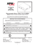
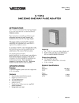
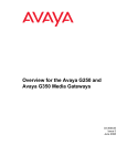
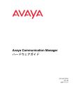
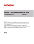
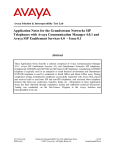
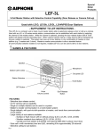
Why the Avaya G860 Media Gateway
Avaya G860 Media Gateway Setup
Why the Avaya G860 Media Gateway
The Avaya G860 Media Gateway allows call center customers to consolidate facilities and
reduce communications costs. The media gateway concentrates incoming PSTN traffic over
several DS3 lines while supporting VoIP telephony in the call center itself.
The use of voice over IP (VoIP) and conversion from DS1 to DS3 lines eliminate the large
number of DS1 interfaces required to support the same amount of call traffic. The Avaya G860
Media Gateway supports up to 6000 channels of session IP (SIP) VoIP telephony. It uses N+1
redundancy of media gateway, Ethernet switch, shelf controller, and power supply modules to
achieve high availability in mission critical applications.
In the sample call center configuration shown here, a simulated PSTN delivers customer calls
using a DS3 interface to the Avaya G860 Media Gateway. The media gateway establishes calls
with the Avaya S8720 or S8730 Media Server via SIP signaling and routes all Real-time
Transport Protocol (RTP) traffic to the appropriate media resources within the Avaya G650
Media Gateway or Avaya endpoints. Avaya Communication Manager delivers the calls to an
agent phone.
Duplex ch 1 ch 2
Sample configuration using the Avaya G860 Media Gateway
disc
2
1
0
Duplex ch 1 ch 2
2
2
0
4
4
Simplex
3
3
1
UID
1
5
5
COMPACT
disc
5
3
1
5
3
1
4
2
0
COMPACT
1
2
UID
CD-RW
0
Avaya S8720
Servers
RX/TX
RX/TX
RX/TX
RX/TX
PWR
PWR
RX/TX
RX/TX
RX/TX
RX/TX
ALRM
ALRM
ALRM
ALRM
FMR-5
3B
2B
1B
SWAP
READY
RX/TX
RX/TX
ALRM
ALRM
IOIO
ALRM
2B
1B
ATM
3A
IOIO
ALARM
ALRM
3A
2A
3B
POWER
SWAP
READY
ER
LT
PSTN
PRI
FAU
LT
ER
PSU-5/30/DC
POW
T3
FAU
ER
POW
LT
PSU-5/30/DC
FAU
RESET
RESET
22
CompacIPCI CompacIPCI
READY
HOT
SWAP
READY
HOT
SWAP
16
18
20
24
22
12
14
21
20
10/100M
15
19
23
16
18
24
MGMT (MDI)
11
13
17
12
14
10/100M
MGMT (MDI)
21
11
15
19
23
13
17
SPEED
RESET
COM
LINK
ALARM
USER
ABORT
CP2300S-650
SPEED
RESET
COM
LINK
ALARM
USER
ACTIVITY
ABORT
4
8
10
3
5
7
9
6
8
4
10
5
3
6
POW
EMS
Server
CP2300S-650
PMC
233
ACTIVITY
P
M
C
B
PMC
233
SNMP
7
ACT/LINK
SPEED
ACT/LINK
SPEED
P
M
C
B
ACT/LINK
SPEED
ACT/LINK
SPEED
9
MAJOR
ACO
EMS
Client
2A
1A
HSR
CRITICAL
SHELF
Agent
Phones
1A
PSU-5/30/DC
SYSTEM
MINOR
Avaya G650
Media Gateway
ATM
ALRM
LINK
C
ALRM
LINK
B
RX/TX
ALARM
C
PSTN
RX/TX
ALARM
B
A
ALRM
PSTN
A
LINK
ACT
FAIL
LINK/
ACT
2
SIP
CONSOLE
IP
Network
CONSOLE
SIP
ALRM
2
GBE
1
ACTIVE RING
ALARM
LINK/
ACT
1
ACTIVE RING
LINK
ACT
FAIL
GBE
AC INPUT
DC INPUT
SWAP
READY
Power
FAN OR POWER FAIL
FAN AND POWER OK
6310 Series
14
6310 Series
13
2
12
1
11
SYSTEM FAULT
10
2
9
1
8
SYSTEM FAULT
7
P
M
C
A
6
P
M
C
A
5
ALARM
4
LINK
3
ALARM
2
LINK
1
AC INPUT
DC INPUT
CPC6600
24 PORT
10/100/1000M
SWITCH
Power
FAN OR POWER FAIL
FAN AND POWER OK
CPC6600
24 PORT
10/100/1000M
SWITCH
2
4
Simplex
DVD
Management Platform
Avaya G860
Media Gateway
Customer
Phones
cyg860d1 LAO 091207
Agents can also make outbound calls using the same network. In the sample configuration,
multiple TN799DP C-LAN circuit packs support alternate routing and permit load sharing of calls
delivered by the Avaya G860 Media Gateway.
Avaya G860 Media Gateway Setup
03-601863, Issue 2, November 2008
1
Avaya G860 Media Gateway Setup
Support of multiple gateways and multiple CM servers
To meet high bandwidth requirements and provide more bandwidth than a single G860 can
support, as well as provide redundancy, the Avaya G860 supports the following configurations:
●
Multiple G860 media gateway platforms distributing incoming traffic into multiple
Communication Manager servers
●
Multiple G860 media gateway systems sending incoming traffic into a single
Communication Manager server
●
A single G860 media gateway distributing incoming traffic across multiple Communication
Manager servers
Traffic distribution into multiple Communication Manager servers is controlled on a modules
basis: you must configure each TP-6310 module with a different list of CLAN IP addresses that
correspond to different Communication Manager servers.
Traffic distribution in multiple gateways and multiple CM servers configuration
2
Avaya G860 Media Gateway Setup
03-601863, Issue 2, November 2008
Why the Avaya G860 Media Gateway
What this document covers
This document focuses on the required equipment and the following administration steps for
configuring:
●
A SIP trunk between the Avaya G860 Media Gateway and Avaya Communication
Manager
●
Inbound and outbound call routing
●
Load balancing of inbound traffic among multiple TN799DP C-LAN circuit packs
●
Alternate routing of inbound traffic when the C-LANs become inaccessible or are busied
out
●
SNMP trap receivers to which the Avaya G860 Media Gateway reports alarms
Needed equipment
The Avaya G860 Media Gateway is shipped with the following equipment:
●
Avaya G860 Media Gateway, which at a minimum includes the following components:
- Avaya G860 chassis
- 2 system controllers (Slots 1 & 2)
- ES6600 Ethernet modules (Slots 3 & 4)
- Console cable for system controller administration
- CD-ROM - Mediant 5000/8000 & EMS documentation
●
A Solaris UNIX-based Sunfire server for the Element Management System (EMS) server
software
- Preinstalled Solaris OS Version 10
- 1 Console cable for network administration
- 1 DVD - Solaris 10 Installation for EMS Server
- 1 DVD software Installation & Documentation 5.2.x (media gateway software, EMS
client and server software)
In addition, the following equipment is also required:
●
The Services Platform Server (SPS) for the EMS client software that is used for
operations, administration, management, and provisioning functions. This server is
connected to the customer’s network. A Windows 2000/XP computers are possible
platforms for the EMS client. Avaya Services has chosen the Windows 2003 server as its
standard platform.
Avaya G860 Media Gateway Setup
03-601863, Issue 2, November 2008
3
Avaya G860 Media Gateway Setup
●
Management platform to handle secure access and control if customer has a maintenance
contract with Avaya. For information on how to install and setup this computer, see Secure
Access and Control at http://support.avaya.com/sac/.
The customer supplies the following equipment:
●
A standard 19-in. (48-cm) 4-post equipment rack that is properly installed and solidly
secured to EIA-310D or equivalent standards. A rack cabinet must have adequate
ventilation.
●
DC/AC power supply
●
Power cable from gateway to DC/AC power supply. Wiring needs to be stripped and
connectors attached on site.
●
CAT5 Ethernet cable (gigabit)
●
T3 cable to connect the Trunk Processing Modules (TP-6310s). This cable requires a
female mini-SMB connector.
●
One incoming twin fiber optic cable with Dual-LC plug for each OC-3/STM-1 optical
interface
●
Avaya S8720 in XL configuration or S8730 Server with a DAL2 board installed, configured,
and operating. Only hardware duplication supports the Avaya G860 Media Gateway.
●
Avaya G650 Media Gateway installed and operating. The media gateway must have an
adequate number of TN799DP C-LAN circuit packs and TN2302AP IP Media Processors
or TN2602AP IP Media Resource 320 circuit packs.
The Avaya G860 Media Gateway comes with
●
Trunk Processing Modules (TP-6310s)
●
2 Shelf (system) control cards (SCCs)
●
2 Ethernet switch boards
●
Active and standby Rear Transition Modules (RTMs), DS-3 interfaces for TP-6310s
●
2 SA/RTM for System Controllers, 2 RTM for TP-6310 (Active/Redundant type depending
on configuration. The active TP-6310 RTM has PSTN interfaces, and the redundant
TP-6310 does not.
●
Cable to DS3 line (50-ft [15 m]) comes standard
Other equipment and items:
4
●
DSX3 broadband patch panel with associated monitoring patch panel jacks and cables
(recommended). The patch panel, collocated with the G860 Media Gateway, allows the
unobtrusive observation of incoming and outgoing traffic on the DS3 connection. Contact
your Avaya representative for details.
●
Laptop computer with EMS client installed for staging
Avaya G860 Media Gateway Setup
03-601863, Issue 2, November 2008
Why the Avaya G860 Media Gateway
●
Filled-out planning form with IP addresses. A blank planning form is available on http:/
support.avaya.com within the product documentation for G860 Media Gateway. IP
addresses are required for several items, including certain TN circuit packs, such as
C-LANs, MedPros, and VAL; network servers, such as DNS, NTP, and NMS; and certain
components on the G860 Media Gateway. The following table provides guidance on which
G860 items need IP addresses:
G860 Slots
Module
IP Address/Mask
10
TP 6310-R
9
TP 6310
8
TP 6310 (optional)
7
TP 6310 (optional)
6
N/A
5
N/A
4
Eth Switch (ES)
3
Eth Switch (ES)
2
Sys Controller (SC)
1
Sys Controller (SC)
GLOBAL
Logical Sys Controller (SC)
Laptop access for staging
If you are staging the Avaya G860 Media Gateway, make sure you have the following
equipment and applications available. For detailed information on staging, refer to the internal
Job Aid: Requirements for Staging G860 High Density Trunk Gateway R1 G860 HDTG.
●
Laptop computer running Windows XP, service pack 2
●
Internet Explorer, version 6.0 or higher
●
EMS client software
●
Console cable for EMS server (Cable and serial adapter is shipped with EMS Sunfire
Server)
●
Console cable for the system controller (Cable and serial adapter is shipped with G860
Media Gateway)
●
Ethereal, version 0.10. 12 or higher, or Wireshark, version 0.99.4 or higher, with a specific
AudioCodes plug-in (provided with DVD that ships with G860 Media Gateway)
Avaya G860 Media Gateway Setup
03-601863, Issue 2, November 2008
5
Avaya G860 Media Gateway Setup
●
ACSyslog093 Server (provided with DVD that ships with G860 Media Gateway)
●
BootP server (provided with DVD that ships with G860 Media Gateway)
Pre-configuration tasks
Before beginning the configuration, you need to make sure that you have all the equipment and
it is setup to simulate the customer’s environment as much as possible, including using the
customer’s time zone.
In addition, make sure that the
●
Avaya G860 Media Gateway has power. Refer to Installing and Operating the Avaya G860
Media Gateway (03-601918).
●
AudioCodes EMS server software is installed on the Sun server. Refer to EMS Server
Installation, Operation, and Maintenance Manual (LTRT-94108) and EMS User’s Manual
(LTRT-91006)
●
AudioCodes EMS client software is installed on the laptop. Refer to EMS Server
Installation, Operation, and Maintenance Manual (LTRT-94108) and EMS User’s Manual
(LTRT-91006)
●
EMS server has the latest software version, available from AudioCodes Web site.
●
SC and TP boards have the latest firmware version, available from AudioCodes Web site.
Avaya G860 Media Gateway configuration
The following sections describe how to configure the SIP and PSTN trunks and call routing for
the Avaya G860 Media Gateway. You configure the media gateway using the GUI-based
Element Management System (EMS). If configuring in a staging area, the EMS client software
is installed on the staging laptop. If configuring at the customer’s site, the EMS client software is
installed on the customer’s client computer.
The first part covers configuring the network support parameters. The second part covers
configuring the Trunk Processing Module (TP-6310) board, which controls the call signaling for
and routing between the SIP and DS3 interfaces to which it is connected.
!
Important:
6
Important:
You must lock the TP-6310 board before configuring it and unlock it once you are
done. While the board is locked, it is out of service.
Avaya G860 Media Gateway Setup
03-601863, Issue 2, November 2008
Avaya G860 Media Gateway configuration
Logging into the EMS
Before starting this procedure, the Element Management System (EMS) server software must
be installed and configured on the Sun server and the EMS client software must be installed on
the Windows 2003 server.
1. Double-click the desktop icon on the computer screen.
2. Type in the login, password, and the server IP address of the EMS server.
Configuring network support parameters
The main provisioning screen is the logical/geographical area where the media gateway
resides. This procedure configures the IP addresses to be used to access an NTP server and
SNMP trap receivers.
Avaya G860 Media Gateway Setup
03-601863, Issue 2, November 2008
7
Avaya G860 Media Gateway Setup
1. On the right pane under Regions List, double-click the first row entry.
2. In the right pane under the MGs List, select the entry corresponding to the Avaya G860
Media Gateway to be configured.
3. Under the Media Gateway pane, click Properties.
8
Avaya G860 Media Gateway Setup
03-601863, Issue 2, November 2008
Avaya G860 Media Gateway configuration
4. Click Network Services.
5. In the NTP server field, type in the IP address for the NTP server.
6. In the EMS Trap port field, type in the trap port number (default 162).
7. In the EMS Security Profile field, select EMSSecurityProfile(1).
8. In the NMS IP Address field, type in the IP address of the SPS server.
Note:
Note:
You can designate 2 SNMP trap receivers by filling in the NMS and OSS sections.
9. Click Apply and then Close.
Avaya G860 Media Gateway Setup
03-601863, Issue 2, November 2008
9
Avaya G860 Media Gateway Setup
Locking the TP-6310
1. In the right pane under the MGs List, select the entry corresponding to the Avaya G860
Media Gateway to be configured.
2. Click the MG Status tab to display a replica of the front panel.
Board slots are numbered from 1 to 10 from bottom to top, as displayed on the left side of
the front panel. The Trunk Processing Modules (TP-6310) are in slots 9 and 10.
3. Right-click the active TP-6310 shown in black and select Maintenance > Lock.
4. Click Yes in the confirmation window.
10
Avaya G860 Media Gateway Setup
03-601863, Issue 2, November 2008
Avaya G860 Media Gateway configuration
Configuring the TP-6310 parameters
The Trunk Processing Module (TP-6310) must be locked before starting these steps. See
Locking the TP-6310 on page 10.
1. Right-click the locked TP-6310 shown in black.
2. Click Properties.
3. Under the Parameters pane on the left, select General Settings.
4. Set the IP Address 1 field to the IP address for this TP-6310.
5. Set the None Mode Clk Source field to pstn.
6. Set the SSL/TLS Negotiation field to TLSv1Only.
7. Use the default settings for the other fields.
8. Click Apply and Close.
Avaya G860 Media Gateway Setup
03-601863, Issue 2, November 2008
11
Avaya G860 Media Gateway Setup
Configuring DS3 trunk on the TP-6310
The TP6310 board must be locked before starting these steps. See Locking the TP-6310 on
page 10.
1. In the right pane under the MGs List, select the entry corresponding to the Avaya G860
Media Gateway to be configured.
2. Select the MG Status tab to display a replica of the front panel.
Board slots are numbered from 1 to 10 from bottom to top, as displayed on the left side of
the front panel. The TP-6310s are in slots 9 and 10.
3. Double-click on the locked TP-6310 shown in black.
4. Configure the DS3 trunk as follows:
a. Right-click on the DS3 and select Properties.
b. Set the DS3 clock source to slave.
c. Select either C-Bit or M23 parity, as instructed by the Service Provider.
d. Set the line build-out length.
e. Click Apply.
5. Select the DS1 Trunks tab for the DS1 channel interface parameters you are configuring.
The DS1 Carriers List pane shows the 28 DS1 interfaces comprising this DS3.
12
Avaya G860 Media Gateway Setup
03-601863, Issue 2, November 2008
Avaya G860 Media Gateway configuration
6. Double-click on a particular DS1 interface to set its parameters.
7. Fill in the fields as required by the DS1 service provider.
Avaya G860 Media Gateway Setup
03-601863, Issue 2, November 2008
13
Avaya G860 Media Gateway Setup
8. Click Apply.
9. Select the ISDN/DPNSS tab.
10. Set the Termination Side field to the appropriate value.
This is usually userTerminationSide if the PSTN connection is to a service provider.
11. Click Apply.
Tip:
Tip:
You can use the Profile Management pane at the bottom to define standard
configuration profiles that you can apply to many DS1 interfaces, saving
configuration steps.
12. Click Save to save this DS1 configuration.
13. In the Profile Name field, type a name for this profile.
14. Click OK.
Configuring SIP trunks on the TP-6310
The Trunk Processing Module (TP-6310) must be locked before starting these steps. See
Locking the TP-6310 on page 10.
The trunk between the Avaya G860 Media Gateway and Avaya Communication Manager uses
Transport Layer Security (TLS)1.
1. Double-click on the locked TP-6310 shown in black.
2. Select the SIP tab.
14
Avaya G860 Media Gateway Setup
03-601863, Issue 2, November 2008
Avaya G860 Media Gateway configuration
3. Select the Protocol Settings tab.
4. In the SIP Destination Port field, type 5061.
5. In the Enable Early Media field, select yes
6. In the Transport Type field, select tls.
7. Click Apply and then Close.
8. Under the SIP tab, select the Coders tab to set the codec preferences to be used on the
SIP calls routed to Avaya Communication Manager.
Avaya G860 Media Gateway Setup
03-601863, Issue 2, November 2008
15
Avaya G860 Media Gateway Setup
9. Click on the + icon to add each codec.
Add them in the order of most to least preferred.
10. In the Coders General Settings window, fill in the fields as shown below.
●
Name: type a name if desired
●
Coder Name: G.711 mu-law 64k
●
Packetization Time: 20 ms
●
Coder Rate: 64.0
●
Payload Type: 0
●
Stance Suppression: Disable
11. Click Apply and then Close.
12. Repeat steps 9 through 12 for each supported codec
Note:
16
Note:
The G860 supports the following codecs: G.711 and G.729.
Avaya G860 Media Gateway Setup
03-601863, Issue 2, November 2008
Avaya G860 Media Gateway configuration
13. Select the Trunk Groups tab.
14. Click on the + icon to add a trunk group.
15. In the SIP Trunk Groups pane, fill in the fields as shown below.
●
Name: All Trunks
●
Trunk Group ID: 1
●
First Trunk ID: 1
●
Last Trunk ID: This number corresponds to the number of DS1 interfaces on the
board. If there one DS3 trunk, enter 28. For two DS3 trunks, enter 56. For three DS3
trunks, enter 84.
●
Starting Channel: 1
●
Ending Channel: 24
●
Starting Phone Number: a 7 or 10 digit number. The starting phone number is used
when no ANI information is available in incoming PSTN calls. Each DS0 channel in the
trunk group is assigned a unique number based on this starting phone number.
Avaya G860 Media Gateway Setup
03-601863, Issue 2, November 2008
17
Avaya G860 Media Gateway Setup
16. Click Apply and then Close to display the SIP Trunk Group List.
17. Select the Trunk Group Settings tab.
18. In the Trunk Group ID and Channel Select Mode fields, fill in the appropriate values.
19. Click Apply and then Close.
Call routing configuration
Similar to Avaya Communication Manager, the Avaya G860 Media Gateway must be configured
with SIP and DS3 trunks and with rules to route inbound (DS3 > SIP) and outbound (SIP > DS3)
calls based on information in the incoming call request. You may want to load balance the
incoming traffic from the Avaya G860 Media Gateway across multiple TN799DP C-LAN circuit
packs in the Avaya G650 Media Gateway. All outbound calls should be routed from the
TN799DP C-LAN circuit packs to the Avaya G860 Media Gateway, which routes them to the
DS3 interface on the PSTN side. The routing rules are summarized below.
Call Type
Routing
(G860 to/from C-LANs)
Condition
Inbound
Tel > IP > C-LAN1
Last digit of calling
number = 0-4
Inbound
Tel > IP > C-LAN2
Last digit of calling
number = 5-9
Inbound
Tel > IP > All
All
Outbound
C-LANs > IP > Tel
All
The routing list also has the property that if a call cannot be successfully routed to the
destination specified by a matched rule, then the next rule that matches is used to attempt to
route the call. This can be used to implement a failover strategy if one of the TN799DP C-LAN
circuit packs is not responding or not available. For this feature to work most effectively, we
recommend that during maintenance operations, the Ethernet interface be disabled on a
TN799DP C-LAN circuit pack as well as busying it out.
For more information about determining the best routing and alternate routing configurations,
contact an Avaya software specialist.
18
Avaya G860 Media Gateway Setup
03-601863, Issue 2, November 2008
Avaya G860 Media Gateway configuration
Configuring inbound call routing on the TP-6310
The Trunk Processing Module (TP-6310) must be locked before starting these steps. See
Locking the TP-6310 on page 10.
Note:
Note:
The two rules set up in these steps implement a form of load sharing that is based
on the calling numbers of the inbound traffic.
1. Double-click the locked TP-6310 shown in black.
2. Select the SIP tab.
3. Select the Routing tab to display the SIP Tel to IP Routing List.
4. Click the + icon to add a routing rule.
Routing rules are applied to inbound calls (Tel to IP).
5. In the Name field, type an appropriate name.
Avaya G860 Media Gateway Setup
03-601863, Issue 2, November 2008
19
Avaya G860 Media Gateway Setup
6. In the Source Phone Prefix field, type a match specification, where x matches any digit
in the calling number and [x-y] specifies that the digit in hat position should match any
digit in the range x to y.
7. In the Dest Address field, type the IP address of the TN799DP C-LAN circuit pack to
which the incoming PSTN call is sent.
For example, if the last digit of the calling number ends in 0, 1, 2, 3, or 4, then a SIP
INVITE is sent to C-LAN1. See the table in Call Routing Configuration.
8. Click Apply and then Close.
9. Repeat steps 8 and 9, clicking on the + icon to add each rule.
For example, if the last digit of the calling number ends in 5, 6, 7, 8, or 9, then a SIP
INVITE is sent to C-LAN2. See the table in Call Routing Configuration.
10. Select the Routing Setting tab.
11. In the Enable Alternative Routing field, select y.
12. Use the default settings for the other fields.
13. Click Apply and then Close.
The SIP Tel to IP Routing List appears as:
Configuring outbound call routing on the TP-6310
The Trunk Processing Module (TP-6310) must be locked before starting these steps. See
Locking the TP-6310 on page 10.
1. Double-click on the locked TP-6310 shown in black.
2. Select the SIP tab.
3. Select the Routing tab
20
Avaya G860 Media Gateway Setup
03-601863, Issue 2, November 2008
Avaya G860 Media Gateway configuration
4. Select the IP to Tel tab to display the SIP IP to Tel Routing List.
5. Click the + icon to add a routing rule.
Routing rules are applied to outbound calls (IP to Tel).
6. In the Name field, type an appropriate name.
7. In the Dest Phone Prefix field, type a match specification.
8. In the Source Phone Prefix field, type a match specification.
9. In the Source Address field, type a match specification.
For example, if all calls are to be routed to Trunk group 1, type an * in the fields,
specifying a match on any value.
10. In the Trunk Group ID field, type the destination PSTN trunk group number.
11. Click Apply and then Close.
12. Repeat steps 5 through 11, clicking the + icon to add each rule.
13. When done, click the up-arrow icon to return to the MG Status screen.
Avaya G860 Media Gateway Setup
03-601863, Issue 2, November 2008
21
Avaya G860 Media Gateway Setup
The SIP IP to Tel Routing List appears as:
22
Avaya G860 Media Gateway Setup
03-601863, Issue 2, November 2008
Avaya G860 Media Gateway configuration
Unlocking the TP6310 board
The board must be unlocked for the configuration to be applied to the TP6310 board, after
which it is enabled for service.
1. Click the up-arrow icon to display the MG Status screen.
2. In the right pane under the MGs List, select the entry corresponding to the Avaya G860
Media Gateway to be unlocked.
3. Select the MG Status tab to display a replica of the front panel.
Board slots are numbered from 1 to 10 from bottom to top, as displayed on the left side of
the front panel. The TP6310 boards are in slots 9 and 10.
4. Right-click on the active TP6310 card shown in black and select Maintenance > Unlock.
5. Click Yes in the confirmation window.
The TP6310 board resets and returns to service after several minutes. The Alarm Browser pane
at the bottom of the window indicates the status of the board.
Note:
Note:
It is recommended to verify that all the board elements (DS3, DS1, routing rules,
trunk groups, etc.) are unlocked.
Avaya G860 Media Gateway Setup
03-601863, Issue 2, November 2008
23
Avaya G860 Media Gateway Setup
Avaya Communication Manager configuration
The following sections describe how to configure call routing in Avaya Communication Manager
for the Avaya G860 Media Gateway. Other information about SIP administration can be found in
the online help that is part of the SIP Administration Web interface.
The first part covers configuring the SIP trunks that communicate with the Avaya G860 Media
Gateway. The second part covers call routing:
●
how inbound calls from the Avaya G860 Media Gateway are directly mapped to 5-digit
extensions in Avaya Communication Manager
●
how Automatic Route Selection (ARS) is configured for outbound calls through the Avaya
G860 Media Gateway
Verifying system capacities
You must verify that an adequate number of SIP trunk members are administered for the
system.
1. Log into a SAT session as craft or dadmin.
2. Type display system-parameters customer-options and press Enter.
3. Go to the IP Port Capacities page.
4. In the Maximum Administered SIP Trunks field, verify that you have an adequate
number of trunks.
5. In the Maximum TN2602 Boards with 320 VoIP Channels field, verify that you have an
adequate number of channels.
6. In the ARS? field, verify that it is set to y.
Assigning IP codec sets
1. Type change ip-codec-set n and press Enter.
2. In the Audio Codec field, type in the codec set you want to use.
For example, type G.711MU for G.711 u-law.
24
Avaya G860 Media Gateway Setup
03-601863, Issue 2, November 2008
Avaya Communication Manager configuration
Assigning IP network regions
!
Important:
Important:
The authoritative domain must be the same as that used on the signaling group
screen. Domain is case sensitive.
1. Type change ip-network-region and press Enter.
2. In the Authoritative Domain field, type in the desired domain.
For example, type companyx.com.
3. In the Name field, type in a unique name.
4. In the Codec Set field, type in the codec set you want to use for this network region.
5. Set the Intra- and Inter-region IP-IP Direct Audio fields to yes.
Assigning a node name
In Communication Manager, you must first assign a node name and IP address to each active
TP-6310. This information is used to populate other screens.
1. Type change node-names ip and press Enter.
2. In a blank Name field, type a unique name for the TP-6310.
3. In the IP Address field, type the IP address of the TP-6310.
4. Repeat steps 2 and 3 for each additional TP-6310, if necessary.
5. Press Enter to save your changes.
Adding a signaling group
You must assign a node name and IP address to active TP-6310 before starting this procedure.
See Assigning a node name on page 25. You must also assign an IP network region. See
Assigning IP network regions on page 25.
You need to create a unique signaling group for each SIP trunk.
1. Type add signaling-group next and press Enter.
The system automatically assigns the next available number.
2. In the Group Type field, type or select sip.
Avaya G860 Media Gateway Setup
03-601863, Issue 2, November 2008
25
Avaya G860 Media Gateway Setup
3. In the Transport Method field type tls. Alternatively, you can type tcp but then you must
also set the corresponding setting in the G860 to TCP, and the port number to 5060.
4. In the Near-end Node Name field, type the name of the C-LAN circuit pack to which the
active TP-6310 is programmed to send calls in the Tel to IP routing rules.
5. In the Far-end Node Name field, type the name of the active TP-6310.
6. In both the Near-end Listen Port and Far-end Listen Port fields, type 5061.
7. In the Far-end Network Region field, type a network region number if your system is
divided into network regions.
This number is the network region to which the active TP-6310 is assigned.
8. In the DTMF over IP: field, type rtp-payload.
9. In the Direct IP-IP Audio Connections?: field, type y.
10. Accept the default values on the remaining fields.
11. Press Enter to save your changes.
If using more than one C-LAN for load balancing, repeat these steps for the each C-LAN.
Adding a trunk group
You must add the active TP-6310 to a signaling group before starting this procedure. See
Adding a signaling group on page 25.
!
Important:
Important:
The number of trunk members must be distributed across all the trunk groups
used for the G860 Media Gateway.
1. Type add trunk-group next and press Enter.
The system automatically assigns the next available trunk group number, which shows in
the Group Number field.
2. In the Group Type field, type or select sip.
3. In the Group Name field, type a name for this trunk group as it relates to the active
TP-6310.
4. In the COR: field, type 1.
5. In the TAC field, type a valid number that fits your dial plan.
For more information about dial plans in Communication Manager, see the Administrator
Guide for Avaya Communication Manager, 03-300509, at http:// www.avaya.com/support.
6. In the Direction field set the value to two-way.
26
Avaya G860 Media Gateway Setup
03-601863, Issue 2, November 2008
Avaya Communication Manager configuration
7. In the Service Type field, type or select tie.
8. In the Signaling Group field, type the number of the signaling group to which the active
TP-6310 is assigned.
9. In the Number of Members field, type the number of members that you wish to use for
this trunk group.
Note:
Note:
The maximum number of trunk group members in any one signaling group is 255.
The maximum number of total members is based upon your license agreement. If
you have more than 255 trunk group members in a signaling group, you must
create additional signaling groups.
10. In the Trunk Features section, set the Numbering Format field to public.
11. Accept the default values on the remaining fields.
12. Press Enter to save your changes.
If you have more than one signaling group, repeat these steps for each trunk group.
Defining public numbering format
Avaya Communication Manager must provide the proper calling number when outbound calls
are placed over the SIP trunks. For example, a full 10-digit number includes the CPN prefix plus
5-digit extension.
1. Type change public-unknown-numbering n and press Enter.
2. Fill in all the fields for the number of digits in the extension, the digit with which the
extension starts, and the number of total digits.
Mapping inbound calls (when required)
Inbound calls must be mapped directly to the correct x-digit extensions in Avaya
Communication Manager, if customer requires it.
1. Type change inc-call-handling-trmt trunk-group n and press Enter.
Incoming calls arriving at each SIP trunk are routed to the extension specified by the last 5
digits of the called number. The first six digits are deleted if the calling number is of the
form 1AAANNNXXXX, and the first five are deleted for the form AAANNNXXXX.
Avaya G860 Media Gateway Setup
03-601863, Issue 2, November 2008
27
Avaya G860 Media Gateway Setup
Mapping outbound calls
Automatic Route Selection (ARS) is used to configure Communication Manager for outbound
calls.
!
Important:
Important:
Ensure that all trunk groups are added into any affected routes.
1. Type change dialplan analysis and press Enter to add the feature access code for
outside dialing.
2. Fill in all the fields. For example, type 9 if users must dial 9 to get an outside line, length 1,
and fac for Feature Access Code.
3. Type change feature-access-codes and press Enter.
4. In the Auto Route Selection (ARS) - Access Code 1 field specify the correct access
code for outside dialing. For example, type 9 if users must dial 9 to get an outside line.
5. Type change ars analysis n and press Enter to configure the route selection based
on the number dialed following the access code.
For example, type 720 if users must dial the area code 720 after dialing 9 for outbound
local calls.
6. Type change route-pattern n and press Enter to define the SIP trunk groups to be
selected for the corresponding route pattern.
7. Set Secure SIP field to N.
8. Type change locations and press Enter.
9. In the Proxy Sel. Rte. Pat. field, designate the SIP trunk routing patterns from step 6. This
provides support for features such as call transfer.
Refer to the Call Routing Guide available on the Avaya Support Web site (http://
support.avaya.com) for more information.
28
Avaya G860 Media Gateway Setup
03-601863, Issue 2, November 2008
Verifying network connectivity
Verifying network connectivity
1. To verify network connectivity on the Avaya G860 Media Gateway:
a. In the right pane under the MGs List, select the entry corresponding to the Avaya
G860 Media Gateway that you configured.
b. Select the MG Status tab to display a replica of the front panel.
c. Double-click on the active TP6310 card shown in black and select
d. Verify that the icons for the DS3 entries are green.
e. Double-click on the DS3 entry for the DS1 channel interface parameters that you
configured.
f. Verify that the icons for the DS1 entries are green.
2. To verify network connectivity on the TN799DP C-LAN circuit packs:
a. Log into Communication Manager on the S8720 or S8730 Media Server and start a
SAT session.
b. Type ping IPAddress board location, where IPAddress is the Ethernet
interface on the G860 Media Gateway and location is the board location of the
C-LAN circuit pack within the G650 Media Gateway.
c. Type status signaling-group and press Enter.
d. Verify that the SIP trunks are up between the Avaya Communication Manager and the
G860 Media Gateway and that the transport protocols and ports match (TLS and
5061).
Verifying call routing
Verifying call routing means making calls within a session Internet Protocol (SIP) environment
and between SIP and the public switched telephone network (PSTN).
In general, if a SIP device in the network does not receive an expected response to a SIP
message it has transmitted, the standard procedure is to retransmit that message t an
exponentially decreasing interval (0.5 s, then 1 s, etc.) up to 6 more times. Look for this
behavior at various points in the call routing path if calls are not successful or if calls only remain
established for about 32 s. Most likely, the expected message was not routed properly because
of NAT, dial-peer, DNS, or firewall configuration errors.
Avaya G860 Media Gateway Setup
03-601863, Issue 2, November 2008
29
Avaya G860 Media Gateway Setup
1. Make calls from a telephone on the PSTN to a SIP telephone. If inbound calls fail, verify
that the proper Tel to IP routing rules were defined to support routing SIP calls to the
appropriate C-LANS.
2. Make calls between SIP telephones registered within each proxy to verify successful call
completion.
If outbound calls fail, verify that the proper IP to Tel routing rules were defined to support
routing SIP calls to the appropriate DS3/DS1.
3. Log into a SAT session on the media server.
4. Type list trace station to verify that the call is being properly routed through the
SIP trunk to the G860 Media Gateway.
5. Change the transport protocol to TCP on the SIP trunk and use a SIP-capable protocol
analyzer to monitor the signaling messages.
6. Type change signaling group and press Enter.
7. Change the following fields:
●
Transport Method: tcp
●
Far-end Listen Port: 5060
8. Log into the G860 Media Gateway.
9. Lock the TP-6310.
10. Double-click on the locked TP-6310 shown in black.
11. Select the SIP tab.
12. Select the Protocol Settings tab.
13. Change the following fields:
●
SIP Destination Port tcp
●
Transport Type 5060.
14. Click Apply and then Close.
30
Avaya G860 Media Gateway Setup
03-601863, Issue 2, November 2008
G860 call routing: setting up 'Tel to IP' for redundancy and performance
G860 call routing: setting up 'Tel to IP' for redundancy and
performance
Purpose
The purpose of this section is to provide step-by-step instructions for setting up G860 Trunk
Groups and TEL-to-IP routing on the G860 in order to avoid issues with load balancing and
degraded call performance.
Introduction
The following issues can potentially sabotage a G860/CM integration if proper and complete
administration is not performed:
●
When routing inbound calls to CM (from the PSTN) is based on the ANI of the calling party
and NO ANI is received from the Service Provider. In this case, if the G860 is not setup
correctly, a one-way talk path may result.
●
Failure to administer the G860 and CM so there are enough trunk members in CM trunk
groups as well as the ability to account for 'alternate routes' to CM in the event of network
issues or resource limitations.
This section takes you step-by-step through the administration process to avoid potential pitfalls
in these situations as well discuss the reasons for each step and the concepts involved.
C-LAN and signaling group discussion
The following guidelines are for assigning and configuring SIP trunks and C-LANs to support
G860. It is assumed that the G860 is already configured with a number of DS3 TP6310 boards,
each with a several inbound trunks (DS0 channels within DS3 connections). The sizing of the
inbound trunks may be based on customer specifications, or may be determined from the usual
Erlang calculation analysis based on call traffic estimates and parameters such as busy hour
call rates and call durations.
1. TLS links: Each TP6310 has its own IP address for media and signaling, therefore each
unique pairing of C-LAN <->TP6310 board requires a separate CM TLS link, of which
there are only 16 available on CM (several of which are usually left unused to support
failover of SES server pairs). C-LANs are a relatively inexpensive components to add, but
generally handle more limited traffic when compared to other components such as SES,
Avaya G860 Media Gateway Setup
03-601863, Issue 2, November 2008
31
Avaya G860 Media Gateway Setup
IPSI and the G860/TP6310. Therefore, it makes more sense to dedicate each C-LAN to
support one and only one signaling group. Each signaling-group communicates with only
one TP6310 board (though its likely that a single TP6310 will communicate with more than
one signaling group). It is assumed that each DS3 board is supported by a unique set of
one or more C-LAN's, which serve no other DS3's or endpoints.
Note:
Note:
In CM, it's possible to create two (or more) SIP signaling groups where the
'near-end' and 'far-end' nodes have the same exact values. Doing so does NOT
add to the count of utilized TLS links. Two identical SIP signaling groups will still
only count as one TLS link. This sort of programming can also be used to get
around the SIP trunk group limit of 255 members.
2. SIP trunks: For each set of C-LANs supporting a TP6310-DS3 connection, assign at least
as many CM SIP trunk members as DS0 channels they are supporting. Note that there is a
maximum of 255 members per SIP trunk group. Therefore the C-LANs supporting the max
~640 channels on a DS3 (total number of DS-0s vary by DS-1 signaling type) should have
combined at least that many CM SIP trunk members. This can be achieved by creating
three SIP signaling groups, each with 255 trunk members, using three C-LANs, etc.
3. C-LANs: There is no real upper limit to the number of signaling groups or trunk members
per C-LAN. The number of C-LANs to allocate for each DS3 board should be determined
by the call traffic volume (BHCC) and the desired redundancy.
4. Decide, or estimate, how many SIP calls per hour a C-LAN can handle. This number is not
fixed, but depends on the complexity of the call. A C-LAN may be able to handle up to 9k
calls/hr for a standard, no-frills, inbound-to-CM-endpoint call, but only 50% or less of the
more complex call center calls with multiple connections to announcements, IVR,
transfers, each of which is a separate SIP re-INVITE transaction.
- For a call center, consider starting with no more than 5k calls/hr for each C-LAN.
5. Dividing this calls/hr load for a C-LAN into the total call load for a DS3 connection gives us
the number of C-LANs required to support that connection.
- The G860 can route calls based on dialed digits, which means separate C-LANs
supporting the same DS3 board may see different (uneven) traffic levels based on the
application or service provided on the extensions handled. In this case, C-LAN
allocation may be done according to each type of application traffic on each board.
6. Combining the previous two rules gives the number of CM SIP trunk members on each
C-LAN.
7. If the total SIP trunk use is not close to the CM limit of 5,000 total SIP trunks, and there's
more than one C-LAN supporting a DS3 board, then allocate a number of trunks about
10% greater than the actual number of DS0s. The reason for this is that when the
channels on the DS3 are almost all occupied during very busy periods of time, there is a
greater chance that one or more of the C-LANs supporting that connection will run out of
SIP trunk members.
32
Avaya G860 Media Gateway Setup
03-601863, Issue 2, November 2008
G860 call routing: setting up 'Tel to IP' for redundancy and performance
8. Using the previous example, if you are using three C-LANs to support the full ~640 DS-0
channels on a DS3, you can allocate 255 SIP trunk members on each C-LAN, which is the
maximum amount for one signaling group. Doing this across three trunk-groups gets
765 members (255+255+255=765).
9. Lastly, you want to be sure you have properly set up Alternate Routing in the G860 (which
is discussed below) for the case where you do use up all trunk members in a CM trunk
group. While the G860 does not have the ability to know how many trunk members are
available in a CM trunk group, it can re-route a call to another trunk group when it receives
any one of four (programmable) SIP reason codes. In this case, CM returns a 503 reason
code to the G860 when all the trunk members are active or otherwise unavailable.
Tel to IP: alternate routing
The G860 has the ability to redirect inbound calls (from PSTN to CM) under the following
scenarios:
●
Loss of network connectivity to the C-LAN (C-LAN is no longer pingable by the G860)
●
QoS thresholds exceeded for jitter and/or packet loss
●
Definable SIP reason codes returned to the G860 by CM
None of the scenarios are enabled by default, though, for a thorough G860 implementation, all
three should be enabled.
Tel to IP: routing based on ANI
Normally, when an incoming call arrives at the G860 from the PSTN with no ANI, the G860 will
reference the starting phone number value on the Trunk Group form in order to decide how to
route the call to Communication Manager. For each sequential call on the trunk group, G860
attempts to increment this value by one.
The default value for the starting phone number field is '$$'. A problem can occur if these values
are left unchanged since $$ is non-numeric. Initially, all incoming calls will complete without
incident, though, over time, as the G860 parses SIP messages where the FROM header
contains ever-changing character strings, performance on the T6310 degrades to the point
where calls result in 'one-way' or 'no-way' talkpath. For example:
From: <sip:[email protected]:5061>;tag=1c26166108
Therefore, it is imperative when setting up Trunk Groups on the G860, that this default value is
changed to a valid numeric value.
Avaya G860 Media Gateway Setup
03-601863, Issue 2, November 2008
33
Avaya G860 Media Gateway Setup
Example scenario
Below is the theoretical configuration that will be used in the example:
CM Trunk
Group
Signaling
Group
C-LAN IP
Address
1
1
10.10.10.1
2
2
10.10.10.2
3
3
10.10.10.3
Overview of the necessary steps
The following are the necessary steps for performing G860 administration via EMS. These
steps should be repeated for each TP6310.
1. Enter appropriate Tel-To-IP routing rules to send calls to CM Signaling/Trunk Groups.
2. Select the Routing Setting tab and set the Enable Alternate Routing field to 'yes'.
3. Set the Alternative Routing Mode to 'All' or 'Conn'.
4. Set appropriate values for the QoS fields (Max Allowed Delay and Packet Lost) if you set
the Alternative Routing Mode to ’All’ in step 3.
5. Select the Alternate Tel to IP tab and add up to four table entries with appropriate SIP
Reason codes (add '503' as one of the reason codes).
6. Create at least one G860 trunk group.
7. Select an appropriate 'Starting Phone Number' value for the trunk group (do NOT leave the
default value of '$$' in this field).
34
Avaya G860 Media Gateway Setup
03-601863, Issue 2, November 2008
G860 call routing: setting up 'Tel to IP' for redundancy and performance
Performing G860 administration via EMS
1. Enter appropriate Tel-To-IP routing rules to send calls to CM Signaling/Trunk Groups:
a. Double-click the TP6310 board.
b. Select the SIP tab.
c. Select the Routing tab.
d. Select the Tel To IP tab.
Note:
Note:
Perform these steps for each active TP6310 board.
2. Based on the information in the above figure, add the Tel to IP entries as follows:
Avaya G860 Media Gateway Setup
03-601863, Issue 2, November 2008
35
Avaya G860 Media Gateway Setup
Note:
Note:
Note:
Note:
Double-clicking a row enables you to edit an existing entry.
Selecting + from the upper right corner of the EMS client
to add new entries.
Note:
For each primary rule, there is a nearly identical rule, the difference being the
destination IP address. Since each IP address represents a different CM
Signaling Group, ultimately the call is being sent to a different CM trunk group.
When the G860 sees two identical rules it knows the first one in the list is the
primary route and assigns the second rule to be the alternate route, provided that
alternate routing is enabled.
Note:
The last rule, where Dst Phone Prefix and Src Phone Prefix are set to *, accounts
for the case where a 10-digit Src Phone Prefix (ANI) is not received.
!
Important:
enables you
Important:
Verify that each of these rules is UNLOCKed.
3. Select the Routing Setting tab and set the Enable Alternate Routing field to 'yes'.
4. Set the Alternative Routing Mode to 'All' or 'Conn'.
36
Avaya G860 Media Gateway Setup
03-601863, Issue 2, November 2008
G860 call routing: setting up 'Tel to IP' for redundancy and performance
5. Set appropriate values for the QoS fields (Max Allowed Delay and Packet Lost) if you set
the Alternative Routing Mode to ’All’ in step 4.
The figure below contains values for the settings applied in the above steps.
6. Select the Alternate Tel to IP tab and add up to four table entries with appropriate SIP
Reason codes (add '503' as one of the reason codes).
Currently, in a single CM SIP trunk group there is a limit of 255 trunk members. Notice that
from step 1 an attempt is made to load balance calls across three SIP signaling groups.
However, there is nothing to prevent the G860 from receiving more than 255 simultaneous
calls where the last digit in the callers ANI ends with 0-3. In this case, all the trunk group
members will be exhausted. So, for the 256th call, CM returns a SIP 503 reason code to
the G860, which indicates that no additional trunk members are available. Rules in the
Alternate Tel to IP tab enable you to instruct the G860 what to do when receiving specific
reason codes (up to four entries). Since you know that CM is going to send a SIP 503
reason code, you have instructed the G860 to invoke the alternate route before giving up
on the call.
Avaya G860 Media Gateway Setup
03-601863, Issue 2, November 2008
37
Avaya G860 Media Gateway Setup
!
Important:
Important:
Verify that each of these rules is UNLOCKed.
7. Create at least one G860 trunk group as follows:
a. In the EMS, double-click the TP6310.
b. Select the SIP tab.
c. Select the Trunk Groups tab.
4. Select the Trunk Group.
The Trunk Group form appears.
Note:
38
Note:
The value in the Starting Phone Number field is $$.
Avaya G860 Media Gateway Setup
03-601863, Issue 2, November 2008
G860 call routing: setting up 'Tel to IP' for redundancy and performance
5. Change the value in the Starting Phone Number field to a numeric value. This has to
be done in case any or all incoming calls from the PSTN to the G860 do not contain
ANI. Align the value with the routing rules setup in the Tel to IP routing tab.
Note:
Note:
In the U.S., this will generally be a 10-digit number.
In this example, you have one DS-3. You have created Trunk Group 1 on the G860,
which consists of all 28 DS-1s in the DS-3. For each DS-1 you have also indicated that
all 24 channels are available (you can include a D-channel used for signaling in the
range as the G860 will not try to utilize it for voice).
When ANI is blocked or otherwise not present, the G860 will use the number
100000001 as the starting point for routing calls to CM. As calls come across
B-channels, the G860 will increment this starting number by 1 so that the call can be
properly load balanced across C-LANs using the rules defined in the Tel to IP tab. This
will also enable the G860 to construct SIP messages where FROM message
containing only a numeric value.
For example: From: <sip:[email protected]:5061>;tag=1c26112113
!
Important:
If you have more than one trunk group for a DS-3, set the Starting Phone Number
in each Trunk Group to values that will not overlap. For example, for Trunk Group
1 you could set the Starting Phone Number to 1000000001 and for Trunk Group 2
you would then set the Starting Phone Number to 2000000001.
!
Important:
Verify that each of these rules is UNLOCKed.
Important:
Important:
Conclusion
With the above concepts understood and the necessary steps taken, you should now be ready
to route calls from the PSTN, through the G860 and to the Communication Manager with the
confidence that there is enough redundancy to account for one or several outage scenarios.
Avaya G860 Media Gateway Setup
03-601863, Issue 2, November 2008
39
Avaya G860 Media Gateway Setup
40
Avaya G860 Media Gateway Setup
03-601863, Issue 2, November 2008