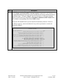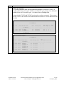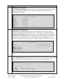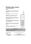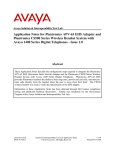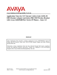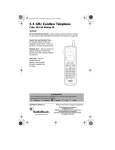
1
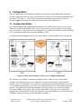
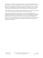
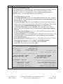
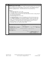
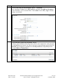
Avaya Solution & Interoperability Test Lab Application Notes for Configuring Multi-Tech FaxFinder® IP Fax Server with Avaya Aura® Communication Manager and Avaya Aura® Session Manager via SIP Trunk Interface - Issue 1.0 Abstract These Application Notes describe the procedures for configuring the Multi-Tech FaxFinder® IP Fax Server with Avaya Aura® Communication Manager and Avaya Aura ® Session Manager using a SIP trunk interface. FaxFinder is an appliance-based fax server that sends and receives fax calls over an IP network. In the tested configuration, FaxFinder interoperated with Avaya Aura® Session Manager to send/receive faxes using SIP trunk facilities. Information in these Application Notes has been obtained through DevConnect compliance testing and additional technical discussions. Testing was conducted via the DevConnect Program at the Avaya Solution and Interoperability Test Lab. RAB; Reviewed: SPOC 7/12/2011 Solution & Interoperability Test Lab Application Notes ©2011 Avaya Inc. All Rights Reserved. 1 of 34 FaxFinder_SM61 1. Introduction These Application Notes describe the procedures for configuring Multi-Tech FaxFinder® IP Fax Server with Avaya Aura® Communication Manager and Avaya Aura® Session Manager. FaxFinder is an appliance-based fax server solution that sends and receives faxes over an IP network. FaxFinder utilizes T.38 Fax over Internet Protocol (FoIP) for sending media. In the tested configuration, FaxFinder interoperated directly with Avaya Aura® Session Manager to send/receive faxes using SIP signaling. 2. General Test Approach and Test Results This section describes the compliance test approach used to verify interoperability of Multi-Tech FaxFinder® IP Fax Server. 2.1. General Test Approach The general test approach was to make intra-site and inter-site fax calls to and from FaxFinder. The inter-site calls were made using SIP or ISDN-PRI trunks between the sites. Faxes were sent with various page lengths, resolutions, and at various fax data speeds. For capacity, a large number of multi-page faxes were continuously sent between the two FaxFinder servers simultaneously. Serviceability testing included verifying proper operation/recovery from failed cables, unavailable resources, and Session Manager and FaxFinder restarts. Fax calls were also tested with different Avaya Media Gateway media resources used to process the fax data between sites. This included the TN2302 MedPro circuit pack, the TN2602 MedPro circuit pack in the Avaya G650 Media Gateway; the integrated VoIP engine of the Avaya G450 Media Gateway and the Avaya MM760 Media Module installed in the Avaya G450 Media Gateway. 2.2. Test Results Multi-Tech FaxFinder® IP Fax Server successfully passed compliance testing. 2.3. General Observations Fax calls consume DSP (Digital Signal Processing) resources for processing fax data on the TN2302AP IP Media Processor (MedPro) circuit pack and the TN2602AP IP Media Processor circuit pack in the Avaya G650 Media Gateway, and the integrated Voice over Internet Protocol (VoIP) engine of the Avaya G450 Media Gateway. To increase the capacity to support simultaneous fax calls, additional TN2302AP and/or TN2602AP MedPro circuit packs need to be installed in the Avaya G650 Gateway, and additional Avaya MM760 Media Module or Modules need to be installed in the Avaya G450 Media Gateway. The information contained in the table below indicates DSP capacities/usage in the Avaya media processors. Customers should work with their Avaya sales representatives to ensure that their fax solutions have adequate licenses and DSP resources to match the intended Fax capacity/usage. RAB; Reviewed: SPOC 7/12/2011 Solution & Interoperability Test Lab Application Notes ©2011 Avaya Inc. All Rights Reserved. 2 of 34 FaxFinder_SM61 Platform Device TN2302, G450, MM760 TN2602 DSP Resources per Platform Device 64 64 DSP Resources per FoIP Call 4 1 Note that the SIP trunk group on Communication Manager for connecting to Session Manager at each site, as well as the SIP or ISDN-PRI trunk group for connecting the 2 sites must be configured with adequate number of trunk group members to support the number of simultaneous fax calls intended. 2.4. Support Technical support for FaxFinder can be obtained by contacting Multi-Tech Systems at: Phone: (800) 972-2439 or (763) 717-5863 Email: [email protected] Web: https://support.multitech.com RAB; Reviewed: SPOC 7/12/2011 Solution & Interoperability Test Lab Application Notes ©2011 Avaya Inc. All Rights Reserved. 3 of 34 FaxFinder_SM61 3. Configuration The test configuration was designed to emulate two separate sites with multiple Port Networks at one site, and modular Gateway resources at the other site. Each site was configured with Multi-Tech FaxFinder® IP Fax Server, Avaya Aura® Communication Manager and Avaya Aura ® Session Manager. Figure 1 illustrates the configuration used in the tested configuration. 3.1. Configuration Details In the tested configuration, Communication Manager Servers and Gateways at the two sites were connected via SIP and ISDN-PRI trunks. Faxes were alternately sent between the two sites using these two facilities. Connections to Session Manager were via SIP trunk facilities, and the FaxFinder servers communicated directly with Session Manager via SIP. Two separate Session Manager Servers were used to connect to the FaxFinder Servers at each site. Figure 1: Multi-Tech FaxFinder® IP Fax Server sample configuration Site A had an Avaya S8800 Communication Manager Server with two Avaya G650 Media Gateways. Each Media Gateway was configured in a separate port networks with separate IP network regions. The FaxFinder server at this site communicated with Session Manager via SIP. In turn, Communication Manager used a SIP Trunk which terminated on a CLAN circuit pack in port network 2 to communicate with Session Manager. IP media resources were provided by Media Processor (MedPro) circuit packs. Two versions of the MedPro circuit pack were tested in this configuration: TN2302AP and TN2602AP. Endpoints at this site included an Avaya 9600 Series IP Telephone (with H.323 firmware), and an analog fax machine. RAB; Reviewed: SPOC 7/12/2011 Solution & Interoperability Test Lab Application Notes ©2011 Avaya Inc. All Rights Reserved. 4 of 34 FaxFinder_SM61 Site B had an Avaya S8300 Communication Manager Server in an Avaya G450 Media Gateway. The FaxFinder server at this site communicated with Session Manager via SIP. On the Avaya G450 Media Gateway, the signaling and media resources supporting a SIP trunk connected to Session Manager were integrated directly on the media gateway processor. Endpoints at this site included Avaya 9600 Series IP Telephones (with H.323 and SIP firmware), and an analog fax machine. The IP telephones were not involved in the faxing operations, they were present in the configuration to verify that VoIP telephone calls did not interfere with FoIP faxing operations. Outbound fax calls originating from FaxFinder were sent to Session Manager first, then to Communication Manager, via the configured SIP trunks. Based on the dialed digits, Communication Manager directed the calls to the local fax machine, or the inter-site trunks (ISDN-PRI or SIP) to reach the remote site. Inbound fax calls to FaxFinder were first received by Communication Manager from the local fax machine or from across either ISDN-PRI or SIP trunks connected to the remote Site. Communication Manager then directed the calls to FaxFinder via the configured Session Manager SIP trunks. RAB; Reviewed: SPOC 7/12/2011 Solution & Interoperability Test Lab Application Notes ©2011 Avaya Inc. All Rights Reserved. 5 of 34 FaxFinder_SM61 4. Equipment and Software Validated The following equipment and software/firmware were used for the sample configuration provided: Equipment Avaya S8800 Servers (at both sites) Avaya S8800 Server (at Site A) Avaya G650 Media Gateway (at Site A) - 2 CLANs - 2 MedPros – TN2302 - 2 MedPros – TN2602 Avaya S8300D Server (at Site B) Software/Firmware Avaya Aura® Session Manager 6.0 (6.0.2.0.602004) 6.1 (6.1.2.0.612004) Avaya Aura® System Manager 6.0, 6.1 Avaya Aura® Communication Manager 6.0 SP1 R016x.00.0.345.0 with patch 18567 Avaya G450 Media Gateway (at Site B) TN799DP - HW01 FW38 & HW13 FW 38 TN2302AP - HW20 FW120 TN2602AP - HW02 FW057 Avaya Aura® Communication Manager 6.0 SP2 R016x.00.1.510.1 with patch 18734 30.14.0/1 Avaya 9620 IP Telephone (SIP) Avaya 9630 IP Telephone (H.323) Analog Fax Machines Multi-Tech FaxFinder® IP Fax Server Multi-Tech FaxFinder® Client software Avaya one-X® Deskphone Edition SIP 2.5 H.323 3.11 1.0.14 2.2.2 The Multi-Tech FaxFinder® IP Fax Server is shipped as an all-in-one appliance. The physical dimensions are 9.1” W x 6.1” L x 1.7” H, roughly the size of a modem. RAB; Reviewed: SPOC 7/12/2011 Solution & Interoperability Test Lab Application Notes ©2011 Avaya Inc. All Rights Reserved. 6 of 34 FaxFinder_SM61 5. Configure Avaya Aura® Communication Manager This section describes the Communication Manager configuration necessary to interoperate with Session Manager and Multi-Tech FaxFinder® IP Fax Server. Connectivity via SIP and PRI trunks between the two sites used existing configurations which follow standard practices. Therefore, it focuses on the configuration of the SIP trunks connecting Communication Manager to the Avaya SIP infrastructure with the following assumption: The examples shown in this section refer to Site A. Unless specified otherwise, these same steps also apply to Site B using values appropriate for that location. The configuration of Communication Manager was performed using the System Access Terminal (SAT). After the completion of the configuration, the save translation command was used to make the changes permanent. 5.1. Steps to Configure Communication Manager The configuration on Communication Manager include the following areas: Verify Communication Manager License (Step 1) Identify IP Interfaces (Step 2) Administer IP Network Regions (Steps 3 – 6) Administer IP Node Name (Step 7) Administer IP Network Map (Step 8) Administer IP Codec Set (Steps 9 – 10) Administer SIP Signaling Group (Step 11) Administer SIP Trunk Group (Steps 12 – 13) Administer Public Unknown Numbering (Step 14) Administer Route Pattern (Step 15) Administer AAR Analysis (Steps 16 – 17) RAB; Reviewed: SPOC 7/12/2011 Solution & Interoperability Test Lab Application Notes ©2011 Avaya Inc. All Rights Reserved. 7 of 34 FaxFinder_SM61 Step 1. Description Verify Communication Manager License Use the display system-parameters customer-options command to verify that the Communication Manager license has proper permissions for features illustrated in these Application Notes. Navigate to Page 2, and verify that there is sufficient remaining capacity for SIP trunks by comparing the Maximum Administered SIP Trunks field value with the corresponding value in the USED column. The license file installed on the system controls the maximum permitted. If there is insufficient capacity, contact an authorized Avaya sales representative to make the appropriate changes display system-parameters customer-options OPTIONAL FEATURES Page IP PORT CAPACITIES Maximum Administered H.323 Trunks: Maximum Concurrently Registered IP Stations: Maximum Administered Remote Office Trunks: Maximum Concurrently Registered Remote Office Stations: Maximum Concurrently Registered IP eCons: Max Concur Registered Unauthenticated H.323 Stations: Maximum Video Capable Stations: Maximum Video Capable IP Softphones: Maximum Administered SIP Trunks: Maximum Administered Ad-hoc Video Conferencing Ports: Maximum Number of DS1 Boards with Echo Cancellation: Maximum TN2501 VAL Boards: Maximum Media Gateway VAL Sources: Maximum TN2602 Boards with 80 VoIP Channels: Maximum TN2602 Boards with 320 VoIP Channels: Maximum Number of Expanded Meet-me Conference Ports: 12000 18000 12000 18000 414 100 18000 18000 24000 24000 522 128 250 128 128 300 2 of 11 USED 96 1 0 0 0 0 0 0 298 0 0 2 0 0 2 0 (NOTE: You must logoff & login to effect the permission changes.) RAB; Reviewed: SPOC 7/12/2011 Solution & Interoperability Test Lab Application Notes ©2011 Avaya Inc. All Rights Reserved. 8 of 34 FaxFinder_SM61 Step 2. Description Identify IP Interfaces Use the list ip-interface clan and list ip-interface medpro commands to identify IP interfaces in each network region. Interfaces in cabinet 01 (port network 1) as indicated in the Slot field are in IP network region 1 as indicated in the Net Rgn field. Testing with the TN2302 and TN2602 circuit packs were done separately. When testing with the TN2302, the TN2602 was disabled (turned off) and vice versa as indicated in the ON field. list ip-interface clan IP INTERFACES ON Slot -y ---01A03 y 02A03 Code/Sfx Node Name/ IP-Address -------- --------------TN799 D CLAN1A 10.64.22.16 TN799 D CLAN2A 10.64.22.19 Mask Gateway Node Skts Warn Net Rgn VLAN ---/24 --------------Gateway001 ---400 --- ---- ---1 n 1 /24 Gateway001 400 2 n Eth Link 2 list ip-interface medpro IP INTERFACES ON Slot -- ----n 01A02 n 02A02 y 01A04 y 02A04 RAB; Reviewed: SPOC 7/12/2011 Code/Sfx Node Name/ IP-Address -------- --------------TN2302 MEDPRO1A 10.64.22.15 TN2302 MEDPRO2A 10.64.22.18 TN2602 MEDPRO1A-2 10.64.22.17 TN2602 MEDPRO2A-2 10.64.22.20 Mask Gateway Node Net Rgn VLAN Virtual Node ---- --------------- --- ---- --------------/24 Gateway001 1 n /24 Gateway001 2 n /24 Gateway001 1 n /24 Gateway001 2 n Solution & Interoperability Test Lab Application Notes ©2011 Avaya Inc. All Rights Reserved. 9 of 34 FaxFinder_SM61 Step 3. Description Administer IP Network Region 1 The configuration of the IP network regions (Steps 3 – 6) was already in place and is included here for clarity. At Site A, the Avaya G650 Media Gateway comprising port network 1 and all IP endpoints were located in IP network region 1. Use the display ip-network-region command to view these settings. A descriptive name was entered for the Name field. IP-IP Direct Audio (Media Shuffling) was enabled to allow audio traffic to be sent directly between IP endpoints without using media resources in the Avaya Media Gateway. This was done for both intra-region and inter-region IP-IP Direct Audio. This is the default setting. Media Shuffling can be further restricted at the trunk level on the Signaling Group form. The Codec Set field was set to the IP codec set to be used for calls within this IP network region. In this case, IP codec set 1 was selected. The default values were used for all other fields. At Site B, all IP components were located in IP network region 1 and the IP network region was configured in the same manner as shown below. display ip-network-region 1 Page 1 of 20 IP NETWORK REGION Region: 1 Location: Authoritative Domain: avaya.com Name: PN1 MEDIA PARAMETERS Intra-region IP-IP Direct Audio: yes Codec Set: 1 Inter-region IP-IP Direct Audio: yes UDP Port Min: 2048 IP Audio Hairpinning? n UDP Port Max: 3329 DIFFSERV/TOS PARAMETERS RTCP Reporting Enabled? y Call Control PHB Value: 46 RTCP MONITOR SERVER PARAMETERS Audio PHB Value: 46 Use Default Server Parameters? y Video PHB Value: 26 802.1P/Q PARAMETERS Call Control 802.1p Priority: 6 Audio 802.1p Priority: 6 Video 802.1p Priority: 5 AUDIO RESOURCE RESERVATION PARAMETERS H.323 IP ENDPOINTS RSVP Enabled? n H.323 Link Bounce Recovery? y Idle Traffic Interval (sec): 20 Keep-Alive Interval (sec): 5 Keep-Alive Count: 5 RAB; Reviewed: SPOC 7/12/2011 Solution & Interoperability Test Lab Application Notes ©2011 Avaya Inc. All Rights Reserved. 10 of 34 FaxFinder_SM61 Step 4. Description Administer IP Network Region 1 – Continued On Page 4, codec sets are defined for inter-region calls. In the case of the compliance test at Site A, calls from IP network Source Region 1 to IP network region 2 (dst rgn 2) used codec set 1. The default values were used for all other fields. At Site B, only one IP network region was used, so no inter-region settings were required. display ip-network-region 1 Source Region: 1 5. 6. Page Inter Network Region Connection Management 4 of I G A R A G L all 20 M t c e dst codec direct WAN-BW-limits Video Intervening Dyn rgn set WAN Units Total Norm Prio Shr Regions CAC 1 1 2 1 y NoLimit n t 3 4 5 6 Administer IP Network Region 2 7 8 At Site A, IP network region 2 was created for Port Network 2 in a similar manner 9 network region 1 shown in Step 3 but with a different name. This was the network 10 11 for SIP Trunk connections to Session Manager. used 12 13 14 display ip-network-region 2 Page 1 of 20 15 IP NETWORK REGION Region: 2 Location: Authoritative Domain: avaya.com Name: PN2 MEDIA PARAMETERS Intra-region IP-IP Direct Audio: yes Codec Set: 1 Inter-region IP-IP Direct Audio: yes UDP Port Min: 2048 IP Audio Hairpinning? n UDP Port Max: 3329 DIFFSERV/TOS PARAMETERS Call Control PHB Value: 46 Audio PHB Value: 46 Video PHB Value: 26 802.1P/Q PARAMETERS Call Control 802.1p Priority: 6 Audio 802.1p Priority: 6 Video 802.1p Priority: 5 AUDIO RESOURCE RESERVATION PARAMETERS H.323 IP ENDPOINTS RSVP Enabled? n H.323 Link Bounce Recovery? y Idle Traffic Interval (sec): 20 Keep-Alive Interval (sec): 5 Keep-Alive Count: 5 as IP region Administer IP Network Region 2 – Continued The inter-region codec setting was created similarly to Step 4. display ip-network-region 2 Source Region: 2 Inter Network Region Connection Management dst codec direct WAN-BW-limits Video Intervening rgn set WAN Units Total Norm Prio Shr Regions 1 1 y NoLimit 2 1 3 3 y NoLimit RAB; Reviewed: SPOC 7/12/2011 Page Solution & Interoperability Test Lab Application Notes ©2011 Avaya Inc. All Rights Reserved. Dyn CAC 3 of I G A A G R L n all all n all 19 M e a s 11 of 34 FaxFinder_SM61 Step 7. Description Administer IP Node Name Use the change node-names ip command to create a node name that maps to the Session Manager IP address. This node name is used in the configuration of the SIP trunk signaling group in Step 11. change node-names ip Page 1 of 2 IP NODE NAMES Name CLAN1A CLAN2A CM-Remote DemoSM Gateway001 MEDPRO1A MEDPRO1A-2 MEDPRO2A MEDPRO2A-2 TR18300 8. IP Address 10.64.22.16 10.64.22.19 10.64.21.111 10.64.20.31 10.64.22.1 10.64.22.15 10.64.22.17 10.64.22.18 10.64.22.20 10.64.10.67 Administer IP Network Map Session Manager and the FaxFinder server were configured to be located in an IP network region different than the default region 1. The region was assigned using the change ip-network-map command. In the case of the compliance test, the IP addresses for these resources at the Main Site were assigned to IP network region 2 as shown in the example below. At the Remote Site, Session Manager and the FaxFinder server were located in the default IP network region 1, so it did not require an IP address map entry. change ip-network-map Page 1 of 63 IP ADDRESS MAPPING Subnet Network Emergency IP Address Bits Region VLAN Location Ext --------------------------------------------- ------ ------ ---- ------------FROM: 10.64.20.31 / 2 n TO: 10.64.20.31 FROM: 10.64.22.170 / 2 n TO: 10.64.22.170 9. Administer IP Codec set Use the change ip-codec-set 1 command to verify that G.711MU or G.711A is contained in the codec list. The example below shows the value used in the compliance test. display ip-codec-set 1 Page 1 of 2 IP Codec Set Codec Set: 1 Audio Codec 1: G.711MU RAB; Reviewed: SPOC 7/12/2011 Silence Suppression n Frames Per Pkt 2 Packet Size(ms) 20 Solution & Interoperability Test Lab Application Notes ©2011 Avaya Inc. All Rights Reserved. 12 of 34 FaxFinder_SM61 Step Description 10. Administer IP Codec set – Fax settings On Page 2, set the FAX Mode field to t.38-standard. This is necessary to support the FaxFinder server assigned to IP network region 2. The Modem Mode field should be set to off. Leave the FAX Redundancy setting at its default value of 0. A packet redundancy level can be assigned to improve packet delivery and robustness of FAX transport over the network (with increased bandwidth as trade-off). Avaya uses IETF RFC-2198 and ITU-T T.38 specifications as redundancy standard. With this standard, each Fax over IP packet is sent with additional (redundant) 0 to 3 previous fax packets based on the redundancy setting. A setting of 0 (no redundancy) is suited for networks where packet loss is not a problem. change ip-codec-set 1 Page 2 of 2 IP Codec Set Allow Direct-IP Multimedia? n FAX Modem TDD/TTY Clear-channel RAB; Reviewed: SPOC 7/12/2011 Mode t.38-standard off US n Redundancy 0 0 3 0 Solution & Interoperability Test Lab Application Notes ©2011 Avaya Inc. All Rights Reserved. 13 of 34 FaxFinder_SM61 Step Description 11. Administer SIP Signaling Group For the compliance test, a signaling group with the associated SIP trunk group was used for routing fax calls to/from the FaxFinder server via Session Manager. For the compliance test at Site A, signaling group 12 was configured using the parameters highlighted below. All other fields were set as described in [3]. The Group Type was set to sip. The Transport Method was set to the recommended default value of tls (Transport Layer Security). As a result, the Near-end Listen Port and Far-end Listen Port are automatically set to 5061. The Near-end Node Name was set to CLAN2A, the node name that maps to the IP address of the CLAN circuit pack used to connect to Session Manager. Node names are defined using the change node-names ip command (see Step 7 above). The Far-end Node Name was set to demoSM. This node name maps to the IP address of the Session Manager server as defined using the change node-names ip command. The Far-end Network Region was set to 2. This is the IP network region which contains Session Manager and FaxFinder. The Far-end Domain was set to avaya.com. This domain is sent in the headers of SIP INVITE messages for calls originating from and terminating to Session Manager using this signaling group. Direct IP-IP Audio Connections was set to y. This field must be set to y to enable Media Shuffling on the trunk level (see Step 3 on IP-IP Direct Audio). The DTMF over IP field was set to the default value of in-band. The default values were used for all other fields. change signaling-group 12 Page 1 of 1 SIGNALING GROUP Group Number: 12 Group Type: sip IMS Enabled? n Transport Method: tls Q-SIP? n IP Video? n Peer Detection Enabled? y Peer Server: SM Near-end Node Name: CLAN2A Near-end Listen Port: 5061 SIP Enabled LSP? n Enforce SIPS URI for SRTP? y Far-end Node Name: demoSM Far-end Listen Port: 5061 Far-end Network Region: 2 Far-end Domain: avaya.com Incoming Dialog Loopbacks: eliminate DTMF over IP: in-band Session Establishment Timer(min): 3 Enable Layer 3 Test? y H.323 Station Outgoing Direct Media? n RAB; Reviewed: SPOC 7/12/2011 Bypass If IP Threshold Exceeded? RFC 3389 Comfort Noise? Direct IP-IP Audio Connections? IP Audio Hairpinning? Initial IP-IP Direct Media? Alternate Route Timer(sec): Solution & Interoperability Test Lab Application Notes ©2011 Avaya Inc. All Rights Reserved. n n y n n 6 14 of 34 FaxFinder_SM61 Step Description 12. Administer SIP Trunk Group For the compliance test, trunk group 12 with the associated signaling group was used for routing fax calls to/from Session Manager. Trunk group 12 was configured using the parameters highlighted below. All other fields were set as described in [3]. On Page 1: The Group Type field was set to sip. A descriptive name was entered for the Group Name. An available trunk access code (TAC) that was consistent with the existing dial plan was entered in the TAC field. The Service Type field was set to tie. The Signaling Group was set to the signaling group shown in the previous step. The Number of Members field contained the number of trunks in the SIP trunk group. It determines how many simultaneous SIP calls can be supported by the configuration. Each SIP call between two SIP endpoints (whether internal or external) requires two SIP trunks for the duration of the call. The default values were used for all other fields. change trunk-group 12 Page 1 of 21 TRUNK GROUP Group Number: Group Name: Direction: Dial Access? Queue Length: Service Type: RAB; Reviewed: SPOC 7/12/2011 12 PN2 to demoSM two-way n 0 tie Group Type: sip COR: 1 Outgoing Display? n TN: 1 CDR Reports: y TAC: *012 Night Service: Auth Code? n Member Assignment Method: auto Signaling Group: 12 Number of Members: 50 Solution & Interoperability Test Lab Application Notes ©2011 Avaya Inc. All Rights Reserved. 15 of 34 FaxFinder_SM61 Step Description 13. Administer SIP Trunk Group – continued On Page 3: Set the Numbering Format field to public. This field specifies the format of the calling party number sent to the far-end. Default values may be used for all other fields. change trunk-group 12 TRUNK FEATURES ACA Assignment? n Page 3 of 21 Measured: none Maintenance Tests? y Numbering Format: public UUI Treatment: service-provider Replace Restricted Numbers? n Replace Unavailable Numbers? n Modify Tandem Calling Number: no Show ANSWERED BY on Display? y 14. Administer Public Unknown Numbering Public unknown numbering defines the calling party number to be sent to the far-end. Use the change public-unknown-numbering command to create an entry that will be used by the trunk groups defined in Steps 12-13. In the example shown below, all calls originating from a 5-digit extension beginning with 2 or 4 and routed across any trunk group (Trk Grp column is blank) were sent as a 5-digit calling party number. change public-unknown-numbering 0 Page 1 of 2 NUMBERING - PUBLIC/UNKNOWN FORMAT Total Ext Ext Trk CPN CPN Len Code Grp(s) Prefix Len Total Administered: 6 5 1 5 Maximum Entries: 9999 5 2 5 5 4 5 Note: If an entry applies to 5 5 5 a SIP connection to Avaya 4 6 4 Aura(tm) Session Manager, 5 7 5 the resulting number must be a complete E.164 number. RAB; Reviewed: SPOC 7/12/2011 Solution & Interoperability Test Lab Application Notes ©2011 Avaya Inc. All Rights Reserved. 16 of 34 FaxFinder_SM61 Step Description 15. Administer Route Pattern Use the change route-pattern command to create a route pattern that will route fax calls to the SIP trunk that connects to the FaxFinder server. The example below shows the route pattern used for the compliance test at the Main Site. A descriptive name was entered for the Pattern Name field. The Grp No field was set to the trunk group created in Steps 12–13. The Facility Restriction Level (FRL) field was set to a level that allows access to this trunk for all users that require it. The value of 0 is the least restrictive level. The default values were used for all other fields. change route-pattern 12 Pattern Number: 12 Pattern Name: To SM SCCAN? n Secure SIP? n Grp FRL NPA Pfx Hop Toll No. Inserted No Mrk Lmt List Del Digits Dgts 1: 12 0 Page 1 of 3 DCS/ IXC QSIG Intw n user 16. Administer AAR Analysis Automatic Alternate Routing (AAR) was used to route calls to FaxFinder via Session Manager. Use the change aar analysis command to create an entry in the AAR Digit Analysis Table for this purpose. The example below shows entries previously created for the Main Site using the display aar analysis 0 command. The 3rd highlighted entry specifies that 5 digit dial string 40000 was to use route pattern 12 to route calls to the FaxFinder server at Site A via Session Manager. The dial string 45000 (the FaxFinder server at Site B) used Route Pattern 15 to route calls between Communication Managers. change aar analysis 0 Page AAR DIGIT ANALYSIS TABLE Location: all Dialed String 10 3 40000 45000 RAB; Reviewed: SPOC 7/12/2011 Total Min Max 4 4 5 5 5 5 5 5 Route Pattern 4 12 12 15 Call Type aar aar aar aar Node Num Solution & Interoperability Test Lab Application Notes ©2011 Avaya Inc. All Rights Reserved. 1 of 2 Percent Full: 1 ANI Reqd n n n n 17 of 34 FaxFinder_SM61 6. Configure Avaya Aura® Session Manager - Overview This section covers the configuration of Session Manager at Site A. Session Manager is configured via an Internet browser using the administration web interface. It is assumed that the setup screens of the administration web interface have been used for initial configurations. For additional information on these installation tasks, refer to [3]. Each SIP endpoint used in the compliance test that registered with Session Manager required that a user and endpoint profile be created and associated with Session Manager. This configuration is not directly related to the interoperability of the products being tested, so it is not included here. These procedures are covered in [3]. This section summarizes the configuration steps that are necessary for interoperating with MultiTech FaxFinder® IP Fax Server. The test environment was previously configured to enable Avaya Aura® Communication Manager and Session Manager at each site to communicate with each other. Details of this configuration are not described in this document, and additional information can be obtained in [3]. The documented configurations were repeated for the Session Manager at Site B using values appropriate for that site from Figure 1. This includes but is not limited to the IP addresses, SIP domain and user extensions. The steps used were: Create a SIP Entity for the FaxFinder Server Create a SIP Entity Link for the FaxFinder Server Create a Routing Policy Create or modify Dial Patterns RAB; Reviewed: SPOC 7/12/2011 Solution & Interoperability Test Lab Application Notes ©2011 Avaya Inc. All Rights Reserved. 18 of 34 FaxFinder_SM61 6.1. Configure Session Manager - Details This section summarizes the applicable user-defined parameters used during the SIP installation procedures. Step 1. Description Login Access the System Manager administration web interface by entering https://<ip-addr>/SMGR as the URL in an Internet browser, where <ip-addr> is the IP address (or FQDN) of the System Manager server. Log in with the appropriate credentials. 2. Create a SIP Entity for the FaxFinder Server Navigate to Routing\SIP Entities and click New to create an Entity definition. In the screenshot below, the Entity RB_FaxServer was previously created using the following settings. RAB; Reviewed: SPOC 7/12/2011 Solution & Interoperability Test Lab Application Notes ©2011 Avaya Inc. All Rights Reserved. 19 of 34 FaxFinder_SM61 Step 3. Description Create a SIP Entity for the FaxFinder Server - Continued Enter a descriptive Name such as RB_FaxServer and enter the FQDN or IP Address for the FaxFinder server as shown below. Select Other for the Entity Type. All other settings were defaults. 4. Create an Entity Link for the FaxFinder Server An Entity Link establishes the details of how Entities will communicate with each other. Use the Add button to create a new link. In this case, Session Manager at the Main Site, demoSM, was configured to communicate with RB_FaxServer using UDP protocol over port 5060 as a Trusted Entity. RAB; Reviewed: SPOC 7/12/2011 Solution & Interoperability Test Lab Application Notes ©2011 Avaya Inc. All Rights Reserved. 20 of 34 FaxFinder_SM61 Step 5. Description Create a Routing Policy Navigate to Routing\Routing Policies and click New to create a routing policy for incoming calls to the FaxFinder server. The illustration below was captured after the Policy RB_Fax_Server_2 had been created and the following steps will describe how this policy was created. A Routing Policy consists of a definition of the SIP Entity as Destination, the Time of Day the policy applies, and the Dial Patterns that will trigger this particular policy. Below are the settings used for this test. Use the Select or Add buttons to create or use existing definitions for each parameter. RAB; Reviewed: SPOC 7/12/2011 Solution & Interoperability Test Lab Application Notes ©2011 Avaya Inc. All Rights Reserved. 21 of 34 FaxFinder_SM61 Step 6. Description Create or Modify Dial Patterns Associating a dial pattern with a SIP Routing Policy instructs Session Manager how to route calls matching the administered Dial Pattern(s). In the test, existing Routing Policies were modified for routing to endpoints or Entities at the Remote Site, and new Dial Patterns were created to route to the Main Site and Remote Site Fax Servers using the existing and new routing policies. In the snapshot below, the Dial Patterns were previously created. The applicable patterns were all 5 Digit extension patterns: dialed numbers beginning with 2 (the local analog fax machine at Site A), dialed numbers beginning with 40 (to route incoming Fax calls to the FaxFinder server at Site B), dialed numbers beginning with 45 (to route to Communication Manager at Site A in order to route via the public network interface between the sites). In addition, an existing 4 digit patterns beginning with 60 was used to route Fax calls to Communication Manager at the Main Site for routing via the public network interfaces to the analog machine at the Remote Site. The ‘40’ and ‘45’ dial patterns were created for this test, all others were in place in the test environment. RAB; Reviewed: SPOC 7/12/2011 Solution & Interoperability Test Lab Application Notes ©2011 Avaya Inc. All Rights Reserved. 22 of 34 FaxFinder_SM61 Step 7. Description Create or Modify Dial Patterns – Continued The entries required to create the new Dial Pattern for routing calls to the FaxFinder server at the Main Site are illustrated below. The Pattern, Min and Max number of digits, and SIP Domain entries were used for this Dial Pattern definition. Click Add to associate the dial pattern with an existing Routing Policy, in this case the RB_Fax_Server_2 policy created in Step 5 above. The Originating Location Name All was used in this case to apply this pattern regardless of originating locations. In the same way, a new Dial Pattern was created (not shown) and associated with the existing policy to route calls to Communication Manager at the Main Site (for onward routing to remote site) using the Dial Pattern 45. This was used to route calls from the Main Site Fax Server to the Remote Site Fax Server. RAB; Reviewed: SPOC 7/12/2011 Solution & Interoperability Test Lab Application Notes ©2011 Avaya Inc. All Rights Reserved. 23 of 34 FaxFinder_SM61 7. Configure Multi-Tech FaxFinder® IP Fax Server This section describes the configuration of Multi-Tech FaxFinder® IP Fax Server. For further instructions on configuring FaxFinder, consult the Administrator User Guide [4]. 7.1. Configure FaxFinder Details The configuration procedures covered in this section include tasks in the following sub categories: 1. System Configuration Launch FaxFinder web configuration tool Configure Network Settings Configure SMTP Settings Configure Time Settings Configure Printers and Network Shares 2. Fax Configuration Configure SIP/T.38 Configure Inbound Routing Configure Outbound rules 3. Configure Users and Contacts The examples shown in this section refer to Site A. Unless specified otherwise, these same steps also apply to Site B using values appropriate from Figure 1. RAB; Reviewed: SPOC 7/12/2011 Solution & Interoperability Test Lab Application Notes ©2011 Avaya Inc. All Rights Reserved. 24 of 34 FaxFinder_SM61 Step 1. Description System Configuration: Launch FaxFinder web configuration tool The FaxFinder configuration is performed using a web browser. Access the tool by pointing your web browser to http://<ip_address>. The home page is displayed below: System Configuration: Configure Network Settings FaxFinder ships with a default network address, so initial configuration needs to be performed from a browser on a host manually configured with an address on the same network segment. Once connected, navigate to System Configuration > Network to assign an appropriate Hostname, IP Address, and other relevant network settings as shown below. Click Save to commit the changes which will reboot the device. To complete the remaining settings, access the web configuration tool from a host that has access to the network segment of the newly configured address. RAB; Reviewed: SPOC 7/12/2011 Solution & Interoperability Test Lab Application Notes ©2011 Avaya Inc. All Rights Reserved. 25 of 34 FaxFinder_SM61 Step Description System Configuration: Configure SMTP Settings FaxFinder can be configured to generate email alerts for a number of events. Navigate to System Configuration > SMTP to configure the outgoing mail gateway, click Save to commit the changes. Below is an example: System Configuration: Configure Time Settings Set the current date and time, it is also recommended that an NTP server be configured to keep the system time in synch with other servers. Click Set and Save when entries are completed in each section. Below is an example of the settings used in the tested configuration: RAB; Reviewed: SPOC 7/12/2011 Solution & Interoperability Test Lab Application Notes ©2011 Avaya Inc. All Rights Reserved. 26 of 34 FaxFinder_SM61 Step Description System Configuration: Configure Printers and Network Shares FaxFinder can be configured to deliver inbound faxes to an email address, to a printer, or to a network share. In the tested configuration, all inbound faxes were saved to a network share. To add a share, click the Add link and provide the path and credentials for the share. The share was previously configured, however the Edit dialog shown below looks similar to the Add dialog: RAB; Reviewed: SPOC 7/12/2011 Solution & Interoperability Test Lab Application Notes ©2011 Avaya Inc. All Rights Reserved. 27 of 34 FaxFinder_SM61 Step 2. Description Fax Configuration: Configure SIP/T.38 Navigate to Fax Configuration > SIP / T.38 and provide the appropriate information for the Session Manager in the SIP section. Note that at this time, UDP is the only option for communications with Session Manager. Default T.38 settings were used in the compliance tests. RAB; Reviewed: SPOC 7/12/2011 Solution & Interoperability Test Lab Application Notes ©2011 Avaya Inc. All Rights Reserved. 28 of 34 FaxFinder_SM61 Step Description Fax Configuration: Configure Inbound Routing Navigate to Fax Configuration > Inbound Routing to define Global, Default and specific Recipient routing rules. For each rule, a network share, email address or printer can be defined for fax delivery. Click on Edit in each section to define or modify the respective rules. Below is a view of the rules used in the tested configuration: Global Routing was configured by clicking the Add link (from the dialog that appears when the Edit link is clicked in Global Routing), this rule applies to all Faxes received, in addition to any other routing rules: A default destination can be defined if no other routing policies apply: A Recipient Routing rule will automatically be created when users are configured (in the following Step 3). RAB; Reviewed: SPOC 7/12/2011 Solution & Interoperability Test Lab Application Notes ©2011 Avaya Inc. All Rights Reserved. 29 of 34 FaxFinder_SM61 Step Description Fax Configuration: Configure Outbound Rules Configuration is needed only if an archive of outbound faxes is to be used. In the tested configuration, outbound archiving was configured to save in PDF format to the network share that was used in the previous step for inbound fax delivery. This was intermittently enabled and disabled by clicking on the Enable Outbound Archive selection on the Fax Configuration > Outbound page. An Outbound approval rule was used to hold outbound faxes for a portion of the testing. This was not a requirement, but was a useful method for traffic test scenarios. The approval setup simply requires a check on the Enable Outbound Approval setting, and selecting a User to approve outbound faxes: RAB; Reviewed: SPOC 7/12/2011 Solution & Interoperability Test Lab Application Notes ©2011 Avaya Inc. All Rights Reserved. 30 of 34 FaxFinder_SM61 Step 3. Description Configure Users and Contacts Two users were configured, an administrator (admin) and a standard user (test). To create a user, navigate to the Users tab, then click the Add link and enter a Username, Full Name, Password and Email address for each user. In addition, if a user has a unique inbound fax extension, a routing rule can be created by providing information in the lower section of the form. Global and Personal contacts and Groups can be configured by clicking on the Contacts tab. In the tested configuration, these were used to simplify sending proceedures. See the Administration Guide [4] for complete instructions on managing contacts. RAB; Reviewed: SPOC 7/12/2011 Solution & Interoperability Test Lab Application Notes ©2011 Avaya Inc. All Rights Reserved. 31 of 34 FaxFinder_SM61 8. Verification Steps The following steps may be used to verify the configuration: From Avaya Aura® Communication Manager SAT, use the status signaling-group command to verify that the signaling groups are in-service. From Communication Manager SAT, use the status trunk-group command to verify that the trunk groups are in-service. Verify that fax calls can be placed to/from Multi-Tech FaxFinder® IP Fax Server servers at each site. From Communication Manager SAT, use the list trace tac command to verify that fax calls are routed to the expected trunks. From Avaya Aura® System Manager, confirm that the Entity Link between Avaya Aura® Session Manager and the FaxFinder server is in service. From the FaxFinder web interface, navigate to Status & Logs > Fax Status to see the current status of each port and any inbound or outbound fax activity currently in progress: Additional System Status information such as the status of connectivity to Session Manager and network shares can be found on the Status & Logs > System Status page: Additional status screens showing mail queues and logs, inbound and outbound fax logs etc are also available (not pictured) from the Status and Logs web pages. RAB; Reviewed: SPOC 7/12/2011 Solution & Interoperability Test Lab Application Notes ©2011 Avaya Inc. All Rights Reserved. 32 of 34 FaxFinder_SM61 9. Conclusion These Application Notes describe the procedures required to configure Multi-Tech FaxFinder® IP Fax Server interoperate with Avaya Aura® Communication Manager and Avaya Aura® Session Manager. Multi-Tech FaxFinder® IP Fax Server successfully passed compliance testing. 10. Additional References [1] Avaya Aura™ Communication Manager Feature Description and Implementation, Doc # 555245-205, Release 6.0, Issue 8.0, June, 2010. [2] Administering Avaya Aura™ Communication Manager, Doc # 03-300509, Release 6.0, Issue 6.0, June, 2010. [3] Administering Avaya Aura™ Session Manager, Doc # 03-603324, Release 6.0, Issue 3, August, 2010. [4] FaxFinder IP® Administrator User Guide, S000493A, Version A Model: FF240-IP Documentation for: Avaya products may be found at http://support.avaya.com. Multi-Tech products may be found at https://support.multitech.com RAB; Reviewed: SPOC 7/12/2011 Solution & Interoperability Test Lab Application Notes ©2011 Avaya Inc. All Rights Reserved. 33 of 34 FaxFinder_SM61 ©2011 Avaya Inc. All Rights Reserved. Avaya and the Avaya Logo are trademarks of Avaya Inc. All trademarks identified by ® and ™ are registered trademarks or trademarks, respectively, of Avaya Inc. All other trademarks are the property of their respective owners. The information provided in these Application Notes is subject to change without notice. The configurations, technical data, and recommendations provided in these Application Notes are believed to be accurate and dependable, but are presented without express or implied warranty. Users are responsible for their application of any products specified in these Application Notes. Please e-mail any questions or comments pertaining to these Application Notes along with the full title name and filename, located in the lower right corner, directly to the Avaya DevConnect Program at [email protected]. RAB; Reviewed: SPOC 7/12/2011 Solution & Interoperability Test Lab Application Notes ©2011 Avaya Inc. All Rights Reserved. 34 of 34 FaxFinder_SM61