1
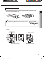
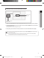
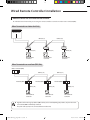
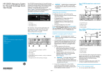
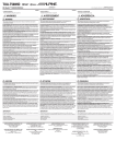
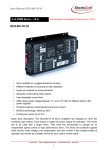
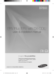
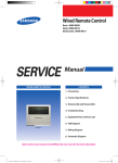
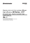
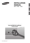
Wired Remote Control MWR-WE10 Air Conditioner installation manual imagine the possibilities Thank you for purchasing this Samsung product. E S F I P D G R A DB98-32811A(2) MWR-WE10_E_IM_32811-2.indd 25 2011-01-20 오후 1:41:58 Safety Information This installation manual explains how to install a Wired Remote Controller connected to the indoor unit of your Samsung system air conditioner. Please read this manual thoroughly before installing the product. (Please refer to appropriate installation for any optional product installation.) WARNING Hazards or unsafe practices that may result in severe personal injury or death. CAUTION Hazards or unsafe practices that may result in minor personal injury or property damage. WARNING Contact a service center for installation. Potential risk of malfunction, water leak, electric shock and fire. Install the product with proper power supply. Potential risk of fire or product damage. Consult the place of purchase or a contact center to disassemble or repair the product. Potential risk of malfunction, electric shock, or fire. The electric work must be done by qualified person according to national wiring regulations and installation guide. If an unauthorized person performs the installation, any resulting defects can cause malfunctions, electrical shocks, or fire accidents. Install the product on a hard and even place that can support its weight. If the place cannot support its weight, the product may fall down and it may cause product damage. Do not move or reinstall the product on your discretion. Potential risk of electric shock or fire. Check if the installation work is done correctly according to the installation manual. Incorrect installation may cause electric shock or fire. When you want to dispose your Wired Remote Controller, ask the service center. 2 MWR-WE10_E_IM_32811-1.indd 2 2010-12-09 오후 4:41:02 ENGLISH CAUTION Do not install the product where there’s combustible gas. Potential risk of fire and explosion. Ensure no water gets into the Wired Remote Controller. Potential risk of electric shock or fire. Install the air conditioner away from direct exposure to sunlight, in room temperature range of 0°C(32°F)~39°C(102°F). Potential risk of electric shock or malfunction. Do not handle the product with sharp objects. Potential risk of electric shock or product damage. Do not install the product in areas exposed to oil or vapor. Potential risk of product damage or malfunction. Do not put undue stress on the power cable. Potential risk of broken cable and fire. Do not install the product in areas with frequent use of acid or alkali spray. Potential risk of electric shock or product malfunction Do not connect power cable to a communication terminal. Potential risk of fire. Be cautious not to interfere any other electrical devices if the product is installed in a place such as hospital. Potential risk of product malfunction. 3 MWR-WE10_E_IM_32811-1.indd 3 2010-12-09 오후 4:41:02 Wired Remote Controller Installation Optional accessories Wired Remote Controller (1) Cable Tie (2) Cable Clamp(3) M4X16 Screw (5) User Manual (1) Installation Manual (1) U Terminal (6) • T he Wired Remote Controller should be installed by an installation expert. • Check and confirm the power is off before installing your Wired Remote Controller. • Install the Wired Remote Controller cables in accordance with the electrical wiring rules, and allow it to pass through the inner area of the wall so that other people can’t reach it. External Dimensions [Unit : mm(inch)] 19.5(0.76) 63.8(2.51) 124.0(4.88) 120.0(4.72) 4 MWR-WE10_E_IM_32811-1.indd 4 2010-12-09 오후 4:41:03 Wired Remote Controller Installation ENGLISH 1. Push the two hooks at the bottom of your Wired Remote Controller at the same time, and then pull up the front cover to separate it from the rear cover. Push the two hooks at the same time. • Insert a flat head screwdriver into the square groove in the upper area of the hook to disassemble it easily. 2. Arrange the power cable and the communication cable so that they fit in the housing along the edges of the rear cover. If you need more space for the wiring work, you can take it off. 15cm(6inch) 10cm(4inch) <When the cable is not concealed> <When the cable is concealed> 5 MWR-WE10_E_IM_32811-1.indd 5 2010-12-09 오후 4:41:04 Wired Remote Controller Installation Wired Remote Controller Installation 3. Using more than two screws, firmly affix the rear cover of the remote controller to the wall, and then connect the power(V1, V2) and communication cables(F3, F4), making sure these cables have reasonable length, to the terminal at the back of the cover. 10mm(0.4inch) or more 10mm(0.4inch) or more 10mm(0.4inch) or more Indoor unit Wire (not supplied) Screw hole Wired Remote Controller 50mm(2inch) or more Rear cover Before fixing the rear cover, secure at least You must fit the screws into 10mm(0.4inch) space of upper side, left side, the screw holes. right side, and 50mm(2inch) space of bottom side. PCB terminal Front cover Do not tighten the screws on the PCB terminal with excessive force. 4. Reassemble your Wired Remote Controller. • A lign the controller with the upper groove first, and insert it by turning it downward as shown in the figure. After assembly, check and confirm that no wires are stuck in the gap between the rear and front cover. • When installing a Wired Remote Controller by using a cable longer than 10m, you must install the communication cable and the power cable separatery. (Electrical interference can cause your Wired Remote Controller to malfunction.) • When installing your Wired Remote Controller on the wall, consider the size of the wire hole, and select a wire with a proper thickness. • Wire that is connectable to Wired Remote Controller PCB. - If you install the Wired Remote Controller by reclaiming, install it according to U-terminal cable specification. - If you install the Wired Remote Controller by using four pieces of PVC wire, remove the 30cm(12inch) of the sheath of the cable and install it only with the four pieces of wires. (Recommended specification: AWG21) • The following are the specs of the compression ring terminal connected to your Wired Remote Controller PCB. Range of Permitted Wires E W Stud D F G L t Rated Stud Size Size Basic Size (mm) AWG mm2 mm2 mm t øD G E F W L 22~16 0.25~1.65 1.5 3 0.7 3.8 10.0 4.5 6.5 6.0 21.2 Maximum distance for connecting communication and power cable: 100m • Screws on the PCB terminal must be tightened with less than 6N-cm tightening torque. If the tightening torque is greater, it may damage the screw thread. 6 MWR-WE10_E_IM_32811-1.indd 6 2010-12-09 오후 4:41:04 Tracking Your Indoor Unit from the Wired Remote Controller ENGLISH Indicates tracking in progress Displays the total number of units searched 1. Tracking of your Wired Remote Controller will automatically start when you turn on the power after installation. 2. If you want to perform tracking again after installation, then press the Esc and Delete buttons at the same time for more than five seconds. The system will reset, and tracking will start again. 3. During tracking, the total number of currently searched indoor units and ventilator(ERV) will be displayed. • If you want to perform tracking again after installation, then press the Esc and Delete buttons at the same time for more than five seconds. • Only the master Wired Remote Controller can display the total number of indoor units and ventilator(ERV). - Slave Wired Remote Controllers do not display the total number of units. 7 MWR-WE10_E_IM_32811-1.indd 7 2010-12-09 오후 4:41:04 Wired Remote Controller Installation Individual Control with Your Wired Remote Controller Individual control means that you are using one remote controller to control one indoor unit or ventilator(ERV). When Connected to an Indoor Unit Only Outdoor Unit COM1(F1,F2) Indoor Unit COM1(F1,F2) Indoor Unit COM2(F3,F4) Indoor Unit COM2(F3,F4) Wired Remote Controller COM2(F3,F4) Wired Remote Controller Wired Remote Controller When Connected to an ventilator(ERV) Only Master ventilator(ERV) COM1(F1, F2) Ventilator(ERV) Ventilator(ERV) COM2(F3, F4) Wired Remote Controller COM1(F1, F2) Ventilator(ERV) 43 COM2(F3, F4) Wired Remote Controller COM2(F3, F4) Wired Remote Controller • R egardless of the indoor group address (RMC address) or the ventilator(ERV) group address, only the indoor unit connected to COM2 is individually controlled. • The power cable (V1, V2) is not connected between indoor units. 8 MWR-WE10_E_IM_32811-1.indd 8 2010-12-09 오후 4:41:06 Group Control with Your Wired Remote Controller ENGLISH Group control means that you are using one Wired Remote Controller to control two or more indoor units and ventilator(ERV) at the same time. When Connected to an Indoor Unit Only (1) Using One Wired Remote Controller to control three indoor Units Outdoor Unit COM1(F1, F2) COM1(F1, F2) COM1(F1, F2) Indoor Unit Indoor Unit COM2(F3, F4) Indoor Unit COM2(F3, F4) Wired Remote Controller (2) Using One Wired Remote Controller to control indoor units connected to different outdoor unit Outdoor Unit COM1(F1, F2) Indoor Unit Outdoor Unit COM1(F1, F2) Indoor Unit COM2(F3, F4) Wired Remote Controller COM2(F3, F4) • R egardless of the indoor unit’s group address (RMC address), only the indoor units connected to COM2 are controlled in group. • The power cable (V1, V2) is not connected between indoor units. • The power cable for your Wired Remote Controller (V1, V2) should be connected to only one indoor unit. • Regardless of your outdoor units, you can control a maximum of 16 indoor units as a group. 9 MWR-WE10_E_IM_32811-1.indd 9 2010-12-09 오후 4:41:06 Wired Remote Controller Installation When Connected to an ventilator(ERV) Only (1) Using One Wired Remote Controller to Control Three ventilator(ERV) Master ventilator(ERV) COM1(F1, F2) COM1(F1, F2) Ventilator(ERV) Ventilator(ERV) COM2(F3, F4) COM1(F1, F2) 43 Ventilator(ERV) COM2(F3, F4) Wired Remote Controller • R egardless of the ventilator(ERV)'s group address (RMC address), only the ventilator(ERV) connected to COM2 controlled in group. • The power cable (V1, V2) is not connected between ventilators(ERV). • The power cable for your Wired Remote Controller (V1, V2) should be connected to only one ventilator(ERV). 10 MWR-WE10_E_IM_32811-1.indd 10 2010-12-09 오후 4:41:07 When Connected to an Indoor Unit and an ventilator(ERV) together (1) Using One Wired Remote Controller to control multiple indoor units and ventilator(ERV) ENGLISH Outdoor Unit COM1(F1,F2) COM1(F1,F2) COM1(F1,F2) Ventilator(ERV) Indoor Unit Indoor Unit Indoor Unit COM2(F3,F4) COM2(F3,F4) COM2(F3,F4) Wired Remote Controller (2) Using One Wired Remote Controller to control indoor units connected to different outdoor unit and ventilator(ERV) Outdoor Unit COM1(F1,F2) Indoor Unit COM2(F3,F4) Outdoor Unit COM1(F1,F2) Wired Remote Controller Indoor Unit COM2(F3,F4) COM2(F3, F4) Ventilator(ERV) • R egardless of the indoor unit’s group address (RMC address), only the indoor units and ventilator(ERV) connected to COM2 are controlled in group. • When controlling indoor units and ventilator(ERV) together in group, you can control maximum of 16 indoor units and ventilator(ERV). • If you want to use the power saving function, you have to connect Wired Remote Controller to only one indoor unit and one ventilator(ERV). • The power cable (V1, V2) is not connected between indoor units. • The power cable for your Wired Remote Controller (V1, V2) should be connected to only one indoor unit. 11 MWR-WE10_E_IM_32811-1.indd 11 2010-12-09 오후 4:41:07 Wired Remote Controller Installation Controlling 2-Remote controller 2-Remote controller is controlling one indoor unit, ventilator(ERV) or one group of indoor units and ventilator(ERV) with two remote controllers. When Connected to an Indoor Unit Only Outdoor Unit COM1(F1,F2) Indoor Unit COM2(F3,F4) Wired Remote Controller (Master) Wired Remote Controller (Slave) When Connected to an ventilator(ERV) Only Master ventilator(ERV) COM1(F1, F2) Ventilator(ERV) COM2(F3, F4) Wired Remote Controller (Master) Wired Remote Controller (Slave) • F or the slave Wired Remote Controller settings, please refer to the sections about the additional functions of the Wired Remote Controller. (Refer to page20) 0 : Master, 1 : Slave 12 MWR-WE10_E_IM_32811-1.indd 12 2010-12-09 오후 4:41:08 ENGLISH When Connected to an Indoor Unit and an ventilator(ERV) Together Outdoor Unit COM1(F1,F2) Indoor Unit COM2(F3,F4) Ventilator(ERV) COM2(F3,F4) Wired Remote Controller (Master) Wired Remote Controller (Slave) • R egardless of the indoor unit group address (RMC address), only the indoor units connected to COM2 are controlled by 2-remote controller. • For the slave Wired Remote Controller settings, please refer to the sections about the additional functions of the Wired Remote Controller. (Refer to page20) 0 : Master, 1 : Slave 13 MWR-WE10_E_IM_32811-1.indd 13 2010-12-09 오후 4:41:09 Wired Remote Controller Installation Initializing Your Wired Remote Controller Communication I f the number of indoor unit or ventilator(ERV) is decreased while you are using your remote control to control one indoor unit, ventilator(ERV) or a group of indoor units and ventilator(ERV), then you need to initialize your remote controller communication. 1. Press the Esc and Delete buttons at the same time for more than five seconds. Your Wired Remote Controller will be initialized, and the device will search for the indoor units/ventilator(ERV) connected to your Wired Remote Controller again. 14 MWR-WE10_E_IM_32811-1.indd 14 2010-12-09 오후 4:41:10 Errors Displayed on Your Wired Remote Controller displayed in the LCD display. ENGLISH Error codes for the Wired Remote Controller and the product connected to your Wired Remote Controller will be LCD Display When an Error Occurs in Your Indoor/Outdoor Units (Product Group Display: A) The product address for the error will be displayed, followed by the error code. Example : Error 101 occurs for Indoor Unit No. 28. Indoor Unit When an Error Occurs in Your Ventilator(ERV) (Product Group Display: B) The product address for the error will be displayed, followed by the error code. Example : Error 121 has occurred at ventilator(ERV) No. 28. Ventilator(ERV) When an Error Occurs in Your Wired Remote Controller Only an error code will be displayed. (No address will be displayed.) Example : Error 601 has occurred at your Wired Remote Controller. 15 MWR-WE10_E_IM_32811-1.indd 15 2010-12-09 오후 4:41:10 Wired Remote Controller Installation Wired Remote Controller Error Codes Display Description Communication error between wired remote controller and indoor/ERV units after successful communication. No communication between Master(Main) and Slave(Sub) wired remote controllers. No communication between wired remote controller and indoor/ERV units Wired remote controller is connected on F1/F2 channel. Two or more wired remote controllers is set as Master(Main). No ERV unit installed for interlocking function. No indoor unit installed for interlocking function. Over 16 indoor/ERV indoor units installed. Indoor units of different temperature setting(°C/°F) connected to same wired remote controller. Wired remote controller(s) has different temperature unit setting with indoor unit(s). Slave(Sub) wired remote controller has different option setting with Maser(MAIN). 16 MWR-WE10_E_IM_32811-1.indd 16 2010-12-09 오후 4:41:11 ENGLISH Display Description Two or more wired remote controllers set as Slave(SUB). No By-Pass function on ERV unit but wired remote controller is set to use By-Pass. No Auto function on ERV unit but wired remote controller is set to use Auto. Temperature sensor Open/Short error. - Memory error. - No damper feedback. • F or the error codes for your indoor/outdoor units and ventilator(ERV), refer to the installation manual of each device. 17 MWR-WE10_E_IM_32811-1.indd 17 2010-12-09 오후 4:41:11 Wired Remote Controller Installation/Service Mode Additional Functions of Your Wired Remote Controller Data bit Main Menu Sub-menu 1 2 3 4 5 6 18 MWR-WE10_E_IM_32811-1.indd 18 2010-12-09 오후 4:41:11 ENGLISH 1. If you want to use the various additional functions for your Wired Remote Controller, press the Set and Esc buttons at the same time for more than three seconds. You will enter the additional function settings, and the [main menu] will be displayed. 2. Refer to the list of additional functions for your Wired Remote Controller on the next page, and select the desired menu. Using the [∧]/[∨] buttons, select a main menu number and press the [>] button to enter the sub-menu setting screen. Using the [∧]/[∨] buttons, select a sub-menu number and press the [>] button to enter data setting screen. When you enter the setting stage, the current setting will be displayed. Refer to the chart for data settings. Using the [∧]/[∨] buttons, select the settings. Press the [>] button to move to the next setting. Press the Set button to save the settings and exit to the sub-menu setting screen. Press the Esc button to exit to normal mode. • While setting the data, you can use the [<]/[>] buttons to set the range of Data bit. • While configuring the setting, press the Esc button to exit to the setting sub-menu without saving your changes. 19 MWR-WE10_E_IM_32811-1.indd 19 2010-12-09 오후 4:41:12 Wired Remote Controller Installation/Service Mode Additional Functions of Your Wired Remote Controller • ‘NONE’ will be displayed if the indoor unit does not support the function. In some cases, the setting may not possible or it may be not applied though it is set on the unit. •If communication initialization is needed after the setting, the system will reset automatically and communication will be initialized. Main Sub menu menu 1 2 1 3 4 5 6 7 Wireless remote controller Option setting/checking (1) Wireless remote controller Option setting/checking (2) 2 3 5 6 Description Cooling/Heating selection 1 0 Use of wireless remote controller MAIN/SUB wired remote controller Temperature unit 2 1 0 – Cooling/Heating, 1 – Cooling only 0 – No use, 1 - Use 3 0 0 –MAIN, 1- SUB 4 0 Temperature sensor selection 1 0 Use of average temperature Use of Auto mode 2 3 0 1 Temperature display 4 0 AC On/Off button function 5 0 1 2 3 4 1 2 3 4 1,2,3 4,5,6 1,2 3,4 1 0 0 0 0 0 0 0 0 0 0 0 Lock of Blade1 Lock of Blade2 Lock of Blade3 Lock of Blade4 Use of By-Pass mode ERV option Use of Auto mode Use of air purification mode Setting/checking Use of external control Temperature control reference Room Temperature compensation Temperature compensation value Number of indoor units Number of connected units Number of ERVs Temperature increment/decrement (°C only) Blade setting/checking 0 1 2 1 2 3 4 Data Factory bit setting Function Factory option setting Software code Software version Indoor unit room temperature Indoor unit EVA IN temperature Indoor unit EVA OUT temperature Indoor unit EEV step Use of central control Use of drain pump Indoor unit option checking (1) Use of electric heater Use of hot water coil Use of external control Use of RPM compensation Filter time Indoor unit option checking (2) Heating temperature compensation EEV stop step in heating Unit - 0 – Celcius(°C), 1 – Fahrenheit(°F) 0 – Indoor unit, 1 – Wired remote controller 0 – No use, 1 - Use 0 – No use, 1 - Use 0 – Set temperature, 1 - Room temperature 0 – Indoor unit + ERV, 1 – Indoor unit only, 2 – ERV only, 0 – Unlock, 1 – lock 0 – Unlock, 1 – lock 0 – Unlock, 1 – lock 0 – Unlock, 1 – lock 0 – No use, 1 - Use 0 – No use, 1 - Use 0 – No use, 1 - Use 0 – No use, 1 - Use -9 ~ 40(°C) 0.1(°C) -9.9 ~ 9.9(°C) 0.1(°C) 0 ~ 16 0 ~ 16 0-1°C, 1-0.5°C, 2-0.1°C 0 – Unchanged 1 – Factory setting Software code Software version Room temperature °C EVA IN temperature °C EVA OUT temperature °C EEV step 0 – No use, 1 - Use 0 – No use, 1 - Use 0 – No use, 1 - Use 0 – No use, 1 - Use 0 – No use, 1 - Use 0 – No use, 1 - Use 0 – 2000 hours, 1 – 1000 hours - 1 0 1~6 1~6 1,2,3 1,2,3 1,2,3 1,2,3 1 2 3 4 1 2 3 - 4 - 0-2°C, 1-5°C - 5 - 0 – 1/80 steps, 1 – 80 - 20 MWR-WE10_E_IM_32811-2.indd 20 2011-01-24 오후 5:52:48 Main Sub menu menu 3 Indoor unit option switch setting/checking 1 AHU setting/checking 2 3 1 2 3 4 5 0 Description Unit Main address (0~63) Main address (0~63) RMC address (00H~2FH) Indoor unit option code Refer to the indoor unit installation manual for details - 1,2 3,4 5,6 1)* - 1)* - 1,2 - 0~30 1 3,4 - 1 RPM 5 - 6 - 0~25 0 – Pre 1 – Medium performance 2 –High performance 0 – 30, 1 - 40, 2 - 50 1 - 0 – No use, 1 - Use - 3,4 5,6 1,2 3,4 1 - 10 ~25°C 28 ~43°C 15~25 18~30 0 – No use, 1 - Use 1°C 1°C 1°C 1°C - 2 - 0 – No use, 1 - Use - 3 4 1,2 3,4 1,2 3,4 - 0 – No use, 1 - Use 0 – No use, 1 - Use 15~30°C 15~30°C 15~30°C 5~15°C 1°C 1°C 1°C 1°C 1,2 - 0~10°C 1°C 0 – Non use of humidifier(0°C) 1 – Use humidifier(10°C) 10~27 RPM 10~27 RPM 0 – No use, 1– Factory setting 1 RPM 1 RPM - filter performance humidity setting/checking Use of discharge temperature control AHU discharge temperature setting/checking Cooling discharge temperature Heating discharge temperature Cooling discharge temperature Fresh Duct discharge temperature checking Heating discharge temperature Use of cold air prevention Use of humidification when Heating thermo off ERV Plus setting/checking Use of fan operation in Defrost Use of humidification when Heating Cooling ERV Plus temperature setting/checking Heating Set temperature ERV Plus Auto mode temperature setting/checking Set temperature difference Setting/checking the compensating temperature A under the Heating EEV control for ERV Plus Checking the compensating temperature B under the Heating EEV control for ERV Plus Air supply RPM ERV Plus fan RPM setting/ checking Air exhaustion RPM Factory setting 5 6 Setting/checking the differential value RPM setting/checking Data Factory bit setting 3,4 - 1,2 3,4 1 - - ENGLISH 2 Indoor unit main address checking Indoor unit main address setting (outdoor unit reset is needed to set) Indoor unit RMC address setting/checking Indoor unit option code setting/checking 1 4 Function - - 1)* The total option codes are 24 digits. You can set six digits at a time and it is distinguished by page number. Press [>] button to go to the next page. Page number Option Code 12 34 56 SEG1 0 SEG2 SEG3 SEG4 SEG5 SEG6 Page number SEG13 SEG14 SEG15 SEG16 SEG17 SEG18 2 Page number SEG7 1 SEG8 SEG9 SEG10 SEG11 SEG12 Page number SEG19 SEG20 SEG21 SEG22 SEG23 SEG24 3 Page number Regardless of Celsius and Fahrenheit setting, service mode setting is available only with Celsius. 21 MWR-WE10_E_IM_32811-2.indd 21 2011-01-24 오후 5:52:48 Wired Remote Controller Installation/Service Mode The example of Wired Remote Controller option setting method 1. Press Set and ESC buttons at the same time for more than 3 seconds. (Main menu) will be displayed and then press the [∧]/[∨] button to select no.1. 2. Press [>] button to select the number you will set. Press [∧]/[∨] button and select no.1 3. Press [>] button to enter the data setting stage. When you enter the setting stage, the current setting value will be displayed. Example of data setting stage display Data bit 12 34 Data1: Both cooling and heating of an indoor unit Data2: Use wireless remote controller Data3: Master wired remote controller Data4: Temperature display – Celsius (°C) 4. Press [<]/[>] button to select the desired Data1. Press [<]/[>] button to select no.1. The wired remote controller option is set from both cooling and heating to cooling only. 5. Press Set button to complete the option setting. Save the setting value and exit to sub menu. 6. Press Esc button to exit to normal mode. 22 MWR-WE10_E_IM_32811-1.indd 22 2010-12-09 오후 4:41:14 Memo ENGLISH 23 MWR-WE10_E_IM_32811-1.indd 23 2010-12-09 오후 4:41:14 MWR-WE10_E_IM_32811-1.indd 24 2010-12-09 오후 4:41:15