1
F1000-G
ISO9001 Certified
Huifeng Inverters
F1000-G Series
0.4~400KW
Instruction Manual
DESIGN WITH INDIVIDUATION
SERVICE WITH ADDED-VALUE
·A·
F1000-G
CONTENTS
I. Product ………………………………………………………………1 1
1.1 Nameplate ……………………………………………………11
1.2 Model Illustration……………………………………………11
1.3 Appearance ……………………………………………………1
1
1.4 Technical Specifications ……………………………………2 2
1.5 Designed Standards for Implementation……………………3 3
1.6 Precautions………………………………………………………3
3
II. Operation Panel……………………………………………………4 5
2.1
2.2
2.3
2.4
2.5
Panel Illustrations……………………………………………45
Panel Operating ……………………………………………5 6
Parameters Setting …………………………………………5 6
Function Codes Switchover in/between Code-Groups…..…5 6
Panel Display ………………………………………………6 8
III. Installation Connection ………………………………………………69
3.1 Installation……………………………………………………79
3.2 Connection ……………………………………………………79
3.3 Wiring Recommended…………………………………………8
11
3.4 Overall Connection and “Three-Line Connection” …………811
IV. Operation …………………………………………………………….912
4.1 Function of Control Terminal ……………………….……………9
13
4.2 Coding Switch…………………………………………………1014
4.3 Main Functions …………………………………………………10
14
V. Basic Parameters ……………………………………………………12
16
VI. Operation Control …………………………………………………1520
6.1 Parameters Setting ……………………………………………1520
6.2 Basic Modes of Speed Control ………………………………1823
VII. Multi-Speed Control….…………………….………………………19
26
·A·
F1000-G
7.1 Parameters Setting …………………………………….………2026
7.2 Multi-Speed Control and Coordinate Speed Control …….……20
26
VIII. Terminal Definition…………………………………………………23
30
8.1 Definable Input Terminal…………………………………………23
30
8.2 Definable Output Terminal….…………………………………2431
8.3 Special Output Terminal…………………………………………24
32
IX. V/F Control and Protection…………………………………………. 34
9.1 V/F Control …………………………………………………….25
34
9.2 Timing Control………………………………………………….28
38
9.3 Programmable Protection Function…………………………….28
38
X. Analog Input and Frequency Output………………………………. 41
Appendix 1 Trouble Shooting………………………………………. 42
Appendix 2 Zoom Table of Function Code…………………………. 43
Appendix 3 Products and Structure …………………………………. 52
·B·
F1000-G
Proper grounding with grounding resistance not
Power range:0.4~400KW; 3 kind of exceeding 4Ω; ensure good ventilation; separate
wiring between control loop and power loop;
structure mode; ISO9001 certified.
shieled wire is used as signal wire.
I. Product
This manual offers a brief introduction of the installation connection for F1000-G series
inverters, parameters setting and operations, and should therefore be properly kept. Please
contact manufacturer or dealer in case of any malfunction during application.
1.1
Nameplate
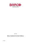
Taking for instance the F1000-G series 15KW
inverter with three-phase input, its nameplate
is illustrated as Fig 1-1.
3Ph: three-phase input; 380V, 50/60Hz: input
voltage range and rated frequency.
3Ph: 3-phase output; 32A, 15KW: rated output
current and power; 0.50 ~ 400.0Hz: output
frequency range.
1.2
Fig 1-1
Nameplate Illustration
Model Illustration
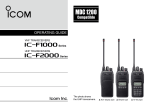
Taking the same instance of 15KW inverter with three-phase, its model illustration is
shown as Fig 1-2.
F1000–G 0150 T3 C
Structure mode code (C: metal hanging; B: plastic housing; D: metal cabinet)
Power input (T3: 3-phase 380VAC input ; S2: single-phase 220VAC input)
Applicable motor power (15KW)
Series code
Manufacturer’s name and upgrade code
Fig 1-2
1.3
Product Model Illustration
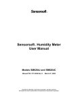
Appearance
The external structure of F1000-G series inverter is classified into plastic and metal
housings. Only wall hanging type is
available for plastic housing while wall
hanging type and cabinet type for metal
housing.
1—Keypad Controller
Good poly-carbon materials are adopted
2—Vent Hole
through die-stamping for plastic housing
3—Heatsink
4—Mounting Hole
with nice form, good strength and
5—Power Terminal
toughness.
6—Control Terminal
Taking F1000-G0015XS2B for instance,
·1·
Fig 1-3
Appearance of Plastic Housing
F1000-G
the external appearance and structure are shown
as in Fig 1-3. Process of
1.Keypad Control Unit
low sheen and silk screen
2.Front Panel
3.Vent
printing are adopted on
4.Body
the housing surface with
5.Control Terminal
soft and pleasant gloss.
6.Power Terminal
Meanwhile, metal housing uses
7.Nameplate
advanced exterior plastic- spraying
8.Outlet Hole
9.Fixed Hole
and powder-spraying process on the
surface with elegant color. Taking
F1000-G0220T3C for instance, its appearance and structure are shown as in Fig 1-4, with
detachable one-side door hinge structure adopted for front cover, convenient for wiring
and maintenance.
1.4 Technical Specifications
Table1-1
Technical Specifications for F1000–G Series Inverters
Items
Input
Output
Contents
3-phase 380V±15%;
single-phase 220V±15%
50/60Hz
3-phase 0~380V;3-phase 0~220V
0.50~400.0Hz
Linear V/F control; space voltage vector+random
PWM
Max 0.01Hz, adjustment allowed
Torque Promotion curve (V/F) can be set
within 1~16;
Current output is restricted, and threshold
current can be adjusted.
Rated Voltage Range
Rated Frequency
Rated Voltage Range
Frequency Range
Control Mode
Frequency Resolution
V/FContrtol
Torque Promotion
Stall Prevention
Overload Capacity
Operation
Function
Protection
Function
150% rated current,1minute
Potentiometer or external analog signal
(0 ~ 5V, 0 ~ 10V, 0 ~ 20mA); keypad
Frequency Setting
(terminal) ▲ / ▼ keys, external control
logic and PLC setting.
Passive contact switch control or
Start/Stop Control
keypad control
0.1 ~ 3000S (time required for certain
Frequency Change Rate
frequency change)
Input out-phase, input under-voltage, DC over-voltage, over-current, over-load, current stall,
over-heat, external disturbance
·2·
F1000-G
LED nixie tube showing present output frequency, present rotate-speed(rpm), present
output current, present output voltage, present linear-velocity, types of faults, and
parameters for the system and operation; LED indicators showing the current working
status of inverter.
Display
Equipment Location
Environment Temperature
Environment
Conditions
Applicable
Motor
Free of tangy caustic gases or dust
-10℃~+50℃
Environment Humidity
Below 90% (no water-bead coagulation)
Vibration Strength
Height above sea level
Below 0.5g (acceleration)
1000m or below
0.4~400KW
1.5 Designed Standards for Implementation
*GB/T 12668.2 2002 Stipulation of rated value of AC low voltage electric drive
system;
*GB 12668.3
2003 Standard for EMC and the specific experimental methods
*GB 12668.5
security requirements relating to electric, heat and other function.
1.6 Precautions
1.6.1
Notice for Application
z Installation and application environment should be free of rain, drips, steam,
dust and oily dirt; without corrosive or flammable gases or liquids, metal
particles or metal powder.
z Environment temperature within the scope of -10℃~+50℃.
z Inverter is installed in a control cabinet, and smooth ventilation should be
ensured.
z Do not drop anything into the inverter.
z Never touch the internal elements within 15 minutes after power off. Wait till it
is completely discharged.
z Input terminals R, S and T are connected to power supply of 380V while output
terminals U, V and W are connected to motor.
z Proper grounding should be ensured with grounding resistance not exceeding
4Ω; separate grounding is required for motor and inverter. No grounding with
series connection is allowed.
z No load switch is allowed at output while inverter is in operation.
z AC reactor or/and DC reactor is recommended when your inverter is above
37KW.
z There should be separate wiring between control loop and power loop to avoid
·3·
F1000-G
any possible interference.
z Signal line should not be too long to avoid any increase with common mode
interference.
z It shall comply with the requirements for surrounding environment as stipulated
in Table 1-1 “Technical Specifications for F1000–G Series Inverter”.
1.6.2
Maintenance
z Cooling fan should be cleaned regularly to check whether it is normal; remove
the dust accumulated in the inverter on a regular basis.
z Check inverter’s input and output wiring regularly.
z Replace inverter’s cooling fan, starting contactor (relay) regularly.
z Check if all terminal wiring screws are fastened and if wirings are aging.
1.6.3
Special Warning!!
z Never touch high-voltage terminals inside the inverter to avoid any electric
shock.
z All safety covers should be well fixed before inverter is power connected, to
avoid any electric shock.
z Only professional personnel are allowed for any maintenance, checking or
replacement of parts.
z No live-line job is allowed.
·4·
F1000-G
II. Operation Panel
Two forms and specifications of
keypad controllers are available,
with “six keys” or “six-key +
potentiometer”.
Besides the function of “stop” and fault “reset”,
“stop/reset” key can also be used to switch over
of function code in a code group or between two
code groups when setting parameters.
Operation panel and monitor screen are both fixed on keypad controller. Two kinds of
controllers (with and without potentiometer) are available for F1000-G series inverters,
and each keypad controller has two kinds of size. Refer to note for Fig2-1.
2.1
Panel Illustration
The panel covers three sections: data display section, status indicating section and keypad
operating section, as shown in Fig. 2-1.
LED shows running frequency, flashing target frequency, function code,
parameter value or fault code.
4 LBDs indicate working status. RUN is lighting while running. FWD is lighting
when working forward and FRQ is lighting when showing frequency.
RUN
FWD
DGT
FRQ
Mode
Se t
▲
▼
Run
Stop
Reset
Min
Max
Press “Mode” for function code, and “set” for original parameters.
▲and▼keys can be used to select function codes and parameters.
Press “set” again to confirm. In the mode of keypad control, ▲and
▼keys can also be used for dynamic speed control. “Run” and
“Stop/Reset” keys control start and stop. Press “Stop/Reset” key to
reset inverter in fault status.
Potentiometer can be used for manual speed control in mode of
analog signals control. External potentiometer or external analog
signal can also be used.
Operation
Panel
LED shows running frequency, flashing target frequency, function code,
parameter value or fault code.
4 LBDs indicate working status. RUN is lighting while running. FWD is lighting
when working forward and FRQ is lighting when showing frequency.
RUN
FWD
DGT
FRQ
Mode
▲
Run
Set
▼
Stop
Reset
Operation
Panel
Press “Mode” for function code, and “set” for original parameters.
▲and▼keys can be used to select function codes and parameters.
Press “set” again to confirm. In the mode of keypad control, ▲and
▼keys can also be used for dynamic speed control. “Run” and
“Stop/Reset” keys control start and stop. Press “Stop/Reset” key to
reset inverter in fault status.
External Dimensions: ① 52×76×17.5;
② 68×100×17
Opening Dimensions: ① 49×73;
② 65×97
Fig.2-1
Operation Panels in Two Kinds
·5·
F1000-G
2.2 Panel Operating
All keys on the panel are available for user. Refer to Table 2-1 for their functions.
Table 2-1
Uses of Keys
Keys
Names
Mode
Mode
Set
Set
To call and save data.
▲
Up
To increase data (speed control or setting parameters)
▼
Down
Run
Run
To decrease data (speed control or setting parameters)
To start inverter; to call jogging operation; to call auto circulating
operation; to switch over display mode.
Stop/reset
Stop or reset
To stop inverter; to reset in fault status; to change function
codes in a code group or between two code groups.
2.3
Remarks
To call function code and switch over display mode.
Parameters Setting
This inverter has numerous function parameters, which the user can modify to effect different modes of
operation control. User needs to realize that user’s password must be entered first if parameters are to be
set after power off or protection is effected, i.e., to call F100 as per the mode in Table 2-2 and enter the
correct code. Default value at manufacturer for user’s password is 8.
Table 2-2
Steps for Parameters Setting
Steps
Keys
1
2
3
▲
4
▲
5
Mode
or ▼
Set
or ▼
Set
Mode
2.4
Operation
Display
Press “Mode” key to display function code
Press “Up” or “Down” to select required function code
To read data set in the function code
To modify data
To show corresponding target frequency by
flashing after saving the set data
To display the current function code
Function Codes Switchover in/between Code-Groups
This has more than 140 parameters (function codes) available to user, divided into 9 sections as
indicated in Table 2-3.
·6·
F1000-G
Table 2-3
Function Code Partition
Group Name
Function
Code Range
Group
No.
Function
Code Range
Group
No.
Basic Parameters
F100~F160
1
Reserved
F600~F660
6
Run Control Mode
F200~F260
2
Multi-Speed
Parameters
F300~F360
3
Timing control and
protection function
F700~F760
7
Terminal Function
Definition
F400~F460
4
Analog signals
input/ourput
F800~F860
8
V/F Control
F500~F560
5
Communication
F900~F960
9
Group Name
of
As parameters setting costs time due to numerous function codes, such function is
specically designed as “Function Code Switchover in a Code Group or between Two
Code-Groups” so that parameters setting become convenient and simple.
Press “Mode” key so that the keypad controller will display function code. If press “▲” or
“▼” key then, function code will circularly keep increasing or decreasing by degrees
within the group; if press again the “stop/reset” key, function code will change circularly
between two code groups when operating the “▲” or “▼” key.
e.g. when function code shows F111, DGT indicator will be on. Press “▲”/ “▼” key,
function code will keep increasing or decreasing by degrees within F100~F160; press
“stop/reset” key again, DGT indicator will be off. When pressing “▲”/ “▼” key, function
codes will change circularly among the 9 code-groups, like F211, F311…F911, F111…,
is indicated the corresponding target frequency
Refer to Fig 2-2 (The sparkling “
values).
Enter correct user’s
password (currently
showing
)
Display
▲
▲
Mode
DGT
Display
Display
Display
Stop/Reset
Display
Fig 2-2 Swtich over in a Code Group or between Different Code-Groups
·7·
DGT
Display
▲
DGT
Off
DGT
On
F1000-G
2.5
Panel Display
Table 2-4
Items and Remarks Displayed on the Panel
Items
HF-0
Remarks
This Item will be displayed when you press “Mode” in stopping status, which indicates
jogging operation is valid.
HF-3,HF-4
This Item will be displayed when you press “Mode” in running status. And press “Set’ to
display relevant contents. HF-1, HF-2, HF-3 and HF-4 correspond to “output
current” , “output voltage”, “rotate speed” and “linear velocity” respectively.
-HF-
It stands for resetting process and will display “0” after reset.
O.C.,O.E.,O.L.,O.
Fault code, indicating “over-current”, “over-voltage”, “over-load”, “over-heat”, “under-voltage for
H.,P.O.,P.F., ERR
input”, “out-phase for input” and “external interference”respectively. It shows “0” after reset.
HF-1,HF-2,
H.H.
Interruption code, indicating “external intrruption” signal input and showing “0” after reset.
F152
Function code (parameter code).
10.00
Indicating inverter’s current running frequency (or rotate speed) and parameter setting values, etc.
Sparkling in stopping status to display target frequency (except for analog signals speed control).
0.
A100、U100
Err1
holding time when changing the rotating direction. When “Stop” or “Free Stop” command is ecxcuted,
the holding time can be canceled
Output current (100A) and output voltage (100V). Keep one digit of decimal when current is below
100A.
Indicating error. It shows when parameters are modified; wrong password or no password is entered.
·8·
F1000-G
III. Installation
& Connection
3.1
Ensuring ventilation andcooling; separate Separate wiring with power loop and control loop. Shielded
grounding with inverter and motor; enough wires required for control wiring; AC or/and DC reactor is
needed in case of large fluctuation with power network or load
carrying capacity with wiring.
Installation
Inverter should be installed vertically, as shown in Fig 3-1. Sufficient ventilation space
should be ensured in its surrounding. Clearance dimensions (recommended) are available
from Table 3-1 for installing the inverter.
Table 3-1
Clearance Dimensions
A
C
Inverter Model
Clearance Dimensions
B≥75mm
D≥75mm
3.2
B
z
z
z
D
D
A
Connection
z
B
Inverter
B≥50mm
Hanging(≥22KW) A≥200mm
Cabinet (110~400KW)
C≥200mm
Inverter
Hanging(<22KW) A≥150mm
Trench
In case of 3-phase input, connect
Hanging
Cabinet
R, S and T terminals (R and T
Fig 3-1 Installation Sketch
terminals for single-phase) with
power source from network and PE(E) to earthing, U, V and W terminals to
motor.
Motor shall have to be ground connected.
External braking cell may be considered for inverter with single-phase input if
load inertia is too large for the built-in braking cell.
For inverter with 3-phase input and power lower than 15kw, braking cell is also
built-in. If the load inertia is moderate, it is Ok to only connect braking
resistance with built-in braking cell.
(The figure is only sketch, terminals order of practical products may be different
·9·
F1000-G
from the above-mentioned figure. Please pay attention when connecting wires)
Introduction of terminals of power loop
Terminal
Terminal Function Description
Marking
Input terminals of three-phase 380V AC voltage (R and
R, S, T
T terminals for single-phase)
Terminals
Power Input
Terminal
Output
Terminal
Grounding
Terminal
U, V, W
Inverter power output terminal, connected to motor.
PE(E)
Inverter grounding terminal or connected to ground.
External braking resistor (Note: no Terminals P or B for
inverter without built-in braking unit).
DC bus-line output, externally connected to braking
resistor
P connected to input terminal “P” of braking unit or
terminal “+”, N connected to input terminal of braking
unit “N” or terminal “-”.
Externally connected to DC reactor
P, B
Braking
Terminal
P, N
P, P+
Wiring for control loop as follows:
A) The following sketch is the control terminals of inverters with single-phase 0.4KW
and 0.75KW.
OUT 12V CM OP1 OP2 OP3 OP4 OP5 OP6 OP7 OP8 V1
B)
V2
V3 FM I2
TA TB
TC
The following sketch is the control terminals for single-phase 0.4KW, 0.75KW
(built-in braking cell), 1.5KW and 1.5KW (built-in braking cell) inveters.
A+ B- OUT 12V CM OP1 OP2 OP3 OP4 OP5 OP6 OP7 OP8 V1 V2 V3 I2 FM IM TA TB TC
C) The following sketch is the control terminals for single-phase 2.2KW inveters.
OUT
OP5
12V
OP1
OP6
OP2
OP7
OP3
OP8
V1
OP4
CM
V2
V3
TA
I2
TB
FM
TC
D) The following sketch is the control terminals for three-phase 0.75~2.2KW inverters.
A+
B-
OUT 12V CM OP1 OP2 OP3 OP4 OP5 OP6 OP7 OP8 V1
V2 V3
I2
FM TA TB
TC
E) The following sketch is the control terminals for three-phase 3.7~400KW inverters.
OUT1 OUT2 +12V CM OP1 OP2 OP3 OP4 OP5 OP6 OP7 OP8 V1
·10·
V2
V3
I2
FM IM TA TB
TC
F1000-G
3.3
Wiring Recommended
Table 3-2
Inverter Model
F1000-G0004S2B
F1000-G0007S2B
Wiring for Power Loop
Lead
Section
Area(mm2)
Inverter
Model
Lead
Section
Area(mm2)
Inverter
Model
Lead
Section
Area(mm2)
4
6.0
F1000-G1320T3C
F1000-G1600T3C
90
120
1.5
2.5
F1000-G0075T3B
F1000-G0110T3C
F1000-G0007XS2B
2.5
F1000-G0150T3C
10
F1000-G1100T3D
90
F1000-G0015S2B
F1000-G0015XS2B
2.5
2.5
F1000-G0185T3C
F1000-G0220T3C
16
16
F1000-G1320T3D
F1000-G1600T3D
90
120
F1000-G0022S2B
4.0
F1000-G0300T3C
25
F1000-G2000T3D
160
F1000-G0007T3B
F1000-G0015T3B
1.5
2.5
F1000-G0370T3C
F1000-G0450T3C
25
35
F1000-G2200T3D
F1000-G2500T3D
240
270
F1000-G0022T3B
2.5
F1000-G0550T3C
35
F1000-G2800T3D
270
F1000-G0037T3B
2.5
F1000-G0750T3C
60
F1000-G3150T3D
290
F1000-G0040T3B
2.5
F1000-G0900T3C
60
F1000-G3550T3D
325
F1000-G0055T3B
4
90
F1000-G4000T3D
325
3.4
F1000-G1100T3C
Overall Connection and “Three- Line” Connection
* Refer to next figure for overall connection sketch for F1000-G series inverters. Wiring mode
is available for various terminals whereas not every terminal needs connection when applied.
R
S
T
R
S
T
U
V
W
E
OP1
OP2
OP3
OP4
OP5
OP6
OP7
OP8
V1
V2
I2
V3
M
TA
TB
TC
FM
V3
F
IM
V3
A
J
12V
OUT
Power Loop Input
ControlLoop Input
Power Loop Output
ControlLoopOutput
Shielded Wire
Basic Wiring Diagram
·11·
F1000-G
OP2
OP3
CM
Inverter
“Three-Line” Connection can fulfill start/stop control by using
parameter setting and terminal definition, as indicated in the right Figure.
If F200=1, F202=1, start/stop command will be excuted by terminals
respectively; F409=6, OP2 is defined as running terminal;
F410=7, OP3 is defined as stop terminal. When OP2 or OP3 are
connected with CM terminal, it will control inverter’s start and
stop respectively. Take care that these two terminals cannot be
connected to CM at the same time.
Three-Line Connection
·12·
F1000-G
IV. Operation
Voltage or current analog signals input; multiple Start/stop control terminals, direction terminal, analog signals
control terminals; coding switch selecting input/output terminals, function switchover terminal,
state-indicating terminal and multiple speedcontrol terminals.
analog singals input range.
It is essential to correctly and flexibly use control terminals for the operation of inverter.
Of course, control terminal are not used separately, but together with corresponding
parameter setting. User can make a flexible use of the basic functions of control terminals,
with reference to the relevant descriptions in the rest of this manual.
4.1
Function of Control Terminal
Table 4-1
Terminal
Function of Control Terminal
Class
OUT
Name
Running Signal
TA
TB
TC
Output
Signal
Relay Contact
FM
Running
Frequency
IM
Current Display
V1
Self-Contained
Power Source
V2
Vo ltage
Control
V3
I2
Current
Control
12V
Power
Source
Voltage Analog
Signals Input Port
Self-contained
Power Source
Ground
Input Port for
CurrentAnalog
Signals
Control Power
Source
Function
The value between this terminal and CM during running is
0V, and 12V when it stops.
For function of these
output terminals,
please refer to mfr’s
TC: co mmon point; TB-TC: normally closed contact;
value; it can be
changed by
TA-TC: normally open contact; contact current not
modifying the
exceeding 2A (Vo ltage not exceeding 250VAC).
parameter.
Real-time output 0~5V or 0~10V; when connected to cymometer, its cathode
connected to V3.
Real-time output 0~20mA; when connected to ammeter,showing inverter’s
output current.(1-phase inverter has no this function)
5V self-contained power source available inside inverter for its own use; it can
only be used for external use as powersource for voltage control signal with
current limit below 20mA.
In case of analog signals speed control, voltage signal is input from this terminal.
Vo ltage input range: 0~5V or 0~10V, grounding: V3. When potentiometer is
used for speed control, this terminal is connected to iput signals, and grounding to
V3. Cautious: V2 and keypad potentiometer cannot be used at the same time.
Grounding end of external control signal (voltage control signal or current source
controlsignal), also 5V power source ground of this inverter.
In case of analog signals speed control, current signal is input fromthis terminal. Current input
range: 0~20mA, grounding: V3. if 4~20mA is input, lower limit of analog signals input can
be adjusted through parameter setting.
Power: 12±1.5V, grounding :CM; current for external use: below 100mA.
OP1
Function
Operation
Jogging Terminal
This terminal is connected to CM, inverter will run by
jogging. Jogging function of the terminal works both in
“Stop” and “Run” states.
OP2
OP3
OP4
Speed
Setting
Multi-Speed
Control Terminal
Normally these three terminals are defined to be “three-stage
speed” or “seven-stage speed” transfer terminals; and may also
use them for other function control.
OP5
OP6
OP7
Free Stop
Function
Operation
Forward
Command
Reverse
Command
Common
Port
Control Power
Source Ground
OP8
CM
Fault Resetting
This terminal is connected to CM during running, inverter
will realize free stop
When this terminal is connected to CM, inverter will run
forward
When this terminal is connected to CM, inverter will
reverse.
Make this terminal connected to CM in fault state to reset
inverter
Ground for 12V power source and other control signal.
·13·
The function of
these Input
terminals is
defined as per
mfr’s value; and
may also be
defined for other
functions by
modifying
parameters.
F1000-G
4.2
*Coding Switch
A red two-digit coding switch SW1 is available around inverter’s control terminal block,
as shown in Fig 4-1.
The function of coding switch is to select the input range (0~5V/0~10V) of input
Terminal V2 for voltage-type analog signals, and must be used together with Function
Code F209. F209 is used to select the input channal of analog signals, to be interpreted as:
{
F209
ON
SW1
1
2
ON
0,select V2 Channel
1,Reserved
2,Select I2 Channel
1
2
SW1
0~5V
selected
Fig 4-1
Coding Switch
Fig 4-2 shows how the coding switch of inverter selects the
range of analog signals. The black blocks in the diagram
F209=0
OK!
indicate the position of SW1.
Chnl V2
Select Channel V2 in the mode of analog signals speed
ON
control, the different position of coding switch can be chosen
0~10V
SW1
0~5V or 0~10V.
selected
1 2
Please note that coding switch can only be used in mode
of analog signals speed control and signal of speed
Fig 4-2
control is input from external terminal. When
Application of Coding Switch
potentiometer of keypad is selected for the input voltage
analog speed control, coding switch must select 0~5V. Keypad voltage analog signals
and terminal voltage analog signals can not be entered at the same time.
4.3
Main Functioins
There are a total 14 kinds of speed control running modes with F1000-G series inverters
covering jogging, keypad, terminal, “three-stage speed”, “seven-stage speed”, “auto
circulating”, analog signal, combination of keypad and terminals, combination of
“three-stage and seven-stage speeds” with terminal, combination of “three-stage and
seven-stage” with keypad, combination of analog signals and “three-stage speed”,
combination of analog signals and “seven-stage speed”, coding speed control and
communication speed control. All these must work with corresponding parameter setting, as
shown in Fig 4-3.
F1000-G series inverters also have other efficient control functions, like switchover of
acceleration/deceleration time, acceleration/deceleration forbidden, state token output,
interruption control, switchover of display contents, etc. Refer to “Terminal Function
Definition”and “Operation Panel”.
·14·
F1000-G
Control
Mode
Output Terminal
Input Terminal
F206=5
F206=4
F206=3
F206=2
F416, F417
Definition of Terminal
Function
)
Terminal Signal Type (levelorpulse)
Direction Given byDirection Terminal Pulse
Direction Given byDirection Terminal Level
Direction Given by FWD/REVTerminal Pulse
Direction Given by FWD/REVTerminal Level
Forwards and Reverse Locked
F204=0, F205=3
F204=3, F205=2, F210=0
F204=3, F205=2, F210=1
F204=1, F205=3, F210=0、1
F204=1, F205=1, F210=0、1
F408~ F415
F400~ F407
Coordinate Speed Control with Keypad
and Terminal
Coordinate Speed Control with Analog and
rd
3 Speed
Coordinate Speed Control with Analog
signals and seven-stage Speed
Analog Speed Control
Coding Speed Control
Seven-stage Speed Control
Auto Circulating Speed Control
Coordinate Speed Control with
Multi-Speed and Keypad
Coordinate Speed Control with
Multi-Speed and Terminal
Terminal Speed Control
Three-stage Speed Control
Controled by PC or Plc
By Multi-Speed Control
·15·
F206=0 or 1
Coordinate Speed Control
F204=5
F204=4
F204=3
F204=2
F204=1
F202, F203
Keypad Speed Control
Stop Signal
F200, F201
F204=0
Start/Run Signal
Modes of Operation
Fig 4-3
Terminal
Definition
Control of
Direction
Mode of
Speed Control
Start/Stop
Signal
F1000-G
V. Basic
Parameters
F100
Running characteristics are set forth by compensation Running at parameters set by manufacturer is
curve, acceleration/deceleration time, jogging free running, which adopts keypadcontrol mode,
parametersand other system parameters.
but does notcontain many specialfunctions.
User’s Password
Setting Range:0~9999
Mfr’s Value:8
・Correct user’s password must be entered when power is supplied again or parameter
modification is intended after fault resetting. Otherwise, parameter setting would not be
possible with indicating “Err1”.
・User may modify “User’s Password”, in the same way as modifying other parameters.
F103
Inverter’s Power (kw)
Setting Range: 0.40~400.0
Mfr’s Value: this inverter’s
power value
・This inverter is marked with power, for recording product information.
F106
Inverter’s Input Voltage Type
Setting Range:
0: single phase, 1:three-phase
Mfr’s
Value: Debugging
Value
F107
Output Voltage Proportion
Setting Range: 1~100%
Mfr’s Value: 100%
F111
Max Frequency limit (Hz)
Setting Range:F113~400.0
Mfr’s Value:50.00Hz
・Indicating inverter’s max running frequency (this inveter’s max designed frequency: 400.0Hz).
F112
Min Frequency Limit(Hz)
Setting Range:0.50~F113
Mfr’s Value:0.50Hz
・Showing inverter’s min running frequency. The value of min frequency limit must be set below F113.
F113
Target Frequency (Hz)
Setting Range:F112~F111
Mfr’s Value:10.00Hz
・Indicating the preset frequency. Inverter will run automatically after startup to this frequency in
keypad or terminal control mode.
F114/F116
1st and 2nd Acceleration Time(S)
F115/F117
1st and 2nd Deceleration Time (S)
Setting Range:
0.1~3000
Mfr’s Value:0.4~3.7KW: 5.0S
5.5~30KW:30.0S
37~400KW:60.0S
・Acceleration/Deceleration Time: The time required for acceleration/deceleration from 0
Note 1
(50Hz) to 50Hz (0)
.
F118
Turnover Frequency(Hz)
Setting Range:15.00~400.0
Mfr’s Value:50.00Hz
・Constant torque output when running frequency is below this value, and constant power output
when exceeding this value. Turnover Frequency normally adopts 50Hz.
F119
Latent Frequency(Hz)
Setting Range:F112~F111
Mfr’s Value:5.00Hz
・When output frequency exceeds this value, the status of the output terminal may be defined
as reverse; the status of terminal will have its state restored when below this frequency.
・ When the definable output terminal is defined as the function of “Over Latent
Frequency”, this parameter setting is valid.
F120
Dead -Time of Switch Between
Corotation and Reverse (S)
Setting Range:0.0~3000
Mfr’s Value:0.0S
・If “Stop” signal is given within the“Dead-Time of Switch between Corotation and
Reverse”, this holding(waiting)time can be terminated, and inverter will immediately
switch over to and run in another direction. This function is fit for all modes of speed
·16·
F1000-G
control except auto circulating running.
・This function can alleviate the current impact during direction switch process, with
manufacturer’s setting value at 0S.
F121
Stop Mode
Setting Range: 0: Stop at Deceleration Time
1: Free Stop
Mfr’s Value:0
・“Free Stop” means that motor will have free running with an immediate output cutoff
and stop by friction upon receiving the “stop” command.
・This function can be used for “stop” operation in mode of keypad control and
interrupting direction signal operation in mode of terminal control.
F123 Jogging Function
Setting Range:0:Invalid jogging function 1:Valid jogging function
F124 Jogging Frequency (Hz)
Setting Range: F112~F111
F125 Jogging AccelerationTime(S)
F126 Jogging DecelerationTime(S)
Mfr’s Value: 0.4~3.7KW:5.0S
5.5~30KW:30.0S
37~400KW:60.0S
Setting Range:
0.1~3000
・It includes keypad jogging and terminal jogging.
f
Receivingjogging
operation command
terminal jogging works both in run and stop states.
・Jogging operation on the keypad (in stop state):
a.
Press “Mode” key to display “HF-0”, and
Jogging Operation
Cancel jogging
operation command
Keypad jogging is only valid in stop state while
Mfr’s Value: 1
Mfr’s Value: 5.00Hz
t
press “Set” to confirm showing “0”.
b.
Press “Run”, and inverter will run to “Jogging
Fig 5-1
Jogging Operation
Frequency” (“Keypad Jogging” will be canceled by pressing “Mode” again).
・In case of terminal jogging, make “Jogging” terminal (like OP1) connected to CM, and
inverter will run to the jogging frequency.
Note1
・“Stalling Adjusting” and F120 is invalid in mode of jogging operation.
F127/F129
Skip Frequency A, B (Hz)
Setting Range: 0~400.0
Mfr’s Value: 0Hz
F128/F130
Skip Area A, B (Hz)
Setting Range:±2.5
Mfr’s Value: 0.5
・System resonance will occur around a certain frequency point during motor running. This
parameter is set specifically to avoid resonance.
・ When output frequency reachs the setting value of this parameter, inverter will
automatically run by tripping off this “Skip Frequency”.
·17·
F1000-G
・“Skip Area” referes to the difference value
between upper and lower frequencies of
the skip frequency, e.g., with skip
frequency of 20Hz, and skip area of ±
0.5Hz, automatic tripping off will
happen when inverter has its output within
19.5~20.5Hz (as F1~F2 in Fig 5-2).
・This function is invalid during
acceleration / deceleration process.
F131 Display
Contents
f
F2
F1
t
Fig 5-2
Skip Frequency
Setting Range:
0: Frequency;
1: Rotate Speed;
2: Linear Velocity; 3: Output Voltage; 4: Output Current
Mfr’s Value: 0
F132
Numbers of Motor Poles
Setting Range: 2~100
Mfr’s Value: 4
F133
Drive Ratio of Driven System
Setting Range: 0.10~200.0
Mfr’s Value: 1.00
F134
Range of Linear Velocity
Setting Range: 1~60000
Mfr’s Value: 1800
・F131=0, running frequency, Hz; F131=1, theoretic rotate speed of shaft end of driven
system, rpm; F131=2, theoretic linear velocity of shaft end of driven system; F131=3,
output voltage, V; F131=4, output current, A.
・No matter what values F131 is set, corresponding target frequencies will be sparklingly
showed on the panel when inverter is stopped.
・Calculation on rotate speed and linear velocity
When inverter operates at max frequency limit, the setting value of F134 shall equal to the
product of loaded rotate speed of shaft and its perimeter, with unit subject to user. E.g.,
max frequency limit F111=50.00Hz, number of motor poles F132=4, drive ratio F133=
1.00, radius of drive shaft R=50mm, then,
Perimeter of drive shaft: 2πr=2×3.14×50=314 (mm)
Rotate speed of drive shaft: 60×running frequency/(number of pole pairs×drive
ratio)=60×50/(2×1.00)=1500rpm
shaft linear velocity: rotate speed×perimeter=1500×314=471000 (mm/minute)
If calculation result exceeds the range of F134 (1~60000), unit conversion will be
required. Should a precision of 0.1m/min is needed, F134=4710 can be set. If a value of
1869 is indicated then, it means that the current linear velocity is 1869 decimeter per
minute.
F137 Frequency Memory
Setting Range: 0: Invalid frequency memory 1: Valid frequency memory
Mfr’s Value: 0
・“Frequency memory” will only automatically memorize the frequency values that user
adjusts, in mode of keypad or terminal speed control.
F138 Auto Start of Analog Signals Speed
Setting Range: 0:Auto start; 1: Press “Run” to start
·18·
Mfr’s Value: 0
F1000-G
・“Auto start of analog signal speed control” means, in mode of analog signal speed
control, inverter will automatically run without the signals of “RUN”, once analog signa l
is input.
F139 Auto Start After Power Resupplied or Reset
Setting Range: 0: Invalid;
1: Valid
Mfr’s Value: 0
・“Auto start after power resupplied or reset” means whether there will be auto start after
power resupplied or fault reset in the mode of keypad speed control or terminal speed
control. If “invalid” is selected, inverter can only operate after “Run” signal is given.
F140 Start by the Terminal Direction Signal
Setting Range: 0, Invalid;
1, Valid
Mfr’s Value: 0
・“Start by Terminal Direction Signal” means a direction signal given externally can be
used to start inverter directly without giving a separate “Run” signal in case of keypad
speed control, terminal speed control or their combined speed control.
F160
Restore Mfr’s
Value
Setting Range: 0: Not Restoring Mfr’s Value
1: Restoring Mfr’s Value
Mfr’s Value: 0
・When there is any confusion with inverter’s parameters, manufacturer’s default value
should be restored, just by setting F160 to 1. F160 shall have its value set to 0
automatically when “restoring manufacturer’s value” is completed.
・Restoring manufacturer’s value will not work for the function code in the “Change”
column of the Appendix 2 marked with “○”. These function codes are properly preset
before delivered. Please do not change the parameter of these function codes.
F100
▼
OK!
F160
Set
Fig 5-3
Restoring Manufacturer’s Values
·19·
0
Set
1
▲
F1000-G
VI. Operation Control
6.1
Parameters Setting
F200 Start Control
F201
Running mode is fixed by basic Numerous modes of speed control are
(extra) speed control, start/stop produced by keypad speed control, terminal
(extra) control and direction giving. speed control, multi-speed control, analog
signal speed control and their combinations.
Additional
Start Control
Setting Range: 0:Keypad control; 1:Terminal control; 2~4:Reserved
Mfr’s Value: 0
Setting Range: 0: No additional start function;
1: Keypad control
2: Terminal control
3, 4: Reserved
Mfr’s Value:0
・“Keypad Control” means that start command will be given by the “RUN” key on the
keypad; “Terminal Control” means that start command will be given by the defined
“RUN” terminal. F200 and F201 can be used in combination.
・Inverter will be started by making the defined “start” terminal connected to CM when
using “terminal control”.
F202
Stop Control
Setting Range: 0: Keypad Control;
2~4: Reserved
1: Terminal Control;
F203
Additional
Stop Control
Setting Range: 0: No Additional stop function;
1: Keypad control;
2: Terminal control;
3, 4:Reserved
Mfr’s Value:0
Mfr’s Value:0
・“Keypad Control” means that stop command will be given by the “Stop” key on the
keypad; “Terminal Control” means that stop command will be given by the defined “Stop”
terminal. F202 and F203 can be used in combination.
・Inverter will be stopped by making the defined “stop” terminal connected to CM when
using “terminal control”.
F204
Basic Modes of
Speed Control
Setting Range: 0: Keypad Speed Control; 1: Multi-speed Control ;
2: Terminal Speed Control; 3: Analog Signal Speed Control;
4: Coding Speed Control; 5: Computer or PLC Control
Mfr’s
Value: 0
F205
Additional Mode
of Speed Control
Setting Range:0:No Additional Speed Control Mode; 1: Keypad
Speed Control 2: Multi-speed Control; 3: Terminal Speed Control
Mfr’s
Value: 0
・“Keypad Speed Control” means that running frequency will be set with the “▲”/“▼”
keys on the keypad; “Terminal Speed Control” means that running frequency will be set
with the defined “UP”/“DOWN” terminals; and “Multi-speed Control” refers to
“three-stage Speed Control”, “Seven-stage Speed Control” and auto circulation speed
control with reference to Parameter F210.
・“Analog Signal Speed Control” refers to the speed control by adopting anaolog signals of
“0~5V”, “0~10V” or “0~20mA”. See F209.
·20·
F1000-G
・“Coding Speed Control” refers to the running frequency given to the inverter by combinations
of various switch-statuses of Terminals OP1~OP8.
F206
Direction
Given
Setting Range: 0: Lock corotation; 1: Lock reverse
2: Given direction of forward and reverse terminals level
3: Given direction of forward and reverse terminal pulse
4: Given direction of direction terminal level
5: Given direction of direction terminal pulse
Mfr’s Value:0
・When F206=0 or 1, running direction is decided internally, not controlled by external
signal.
・If a terminal is defined as one to control direction, then its signal form (level or pulse)
shall only depend on Function Code F206, without being controlled by F400~F407
(signal type of terminal).
F209
Selection of Analog
Signal Input Channel
Setting Range: 0:V2 Channel 1: Reserved
2: I2 Channel (0~20mA)
Mfr’s Value: 0
・When F206=2, “forward” and “reverse” are set by the defined “forward terminal” and
“reverse terminal”, in the mode of “level”, i.e., valid when connected to CM and invalid
when disconnected, and inverter will stop as well.
・When F206=3, “forward” and “reverse” are given by the defined “forward terminal” and
“reverse terminal” respectively in the mode of “pulse”, i.e., an instant connection
between “forward terminal” and CM give “forward” signal, and another instant
connection between “reverse terminal” and CM will give “reverse” signal.
・When F206=4, “forward” and “reverse” are given by the defined “direction terminal” in
the mode of “level”, i.e., connection between “direction terminal” and CM give
“reverse” signal, and “forward” signal is given when disconnected from CM.
・When F206=5, “forward” and “reverse” are given by the defined “direction terminal” in
the mode of “pulse”, i.e., instant connection between “direction terminal” give
“forward” signal,
instant connection for one more time give “reverse” signal.
・When delivered by the manufacturer, Terminal OP6 has the signal of forward, and OP7
the signal of reverse.
・Voltage analog signal “0~5V” and “0~10V” are input through V2 channel, the different
position of coding switch (SW1) can be chosen “0~5V” or “0~10V”.
・Current input signal “0~20mA” is input through I2 channel with grounding of V3.
F210
Multi-Speed
Types
Setting Range:0:3-stage speed control; 1:7-stage speed control;
2: Auto-circulation speed control
Mfr’s Value:0
・In case of multi-speed control (F204=1), choice must be made from “3-stage speed
control”, “seven-stage speed control” or “auto-circulation speed control”, of which,
·21·
F1000-G
“auto-circulation speed control” is further divided into “auto circulation of two-stage
speed”, “auto circulation of three-stage speed”, … “auto circulation of seven-stage
speed”, subject to F211. Refer to Table 6-1.
Table 6-1
F204
1
Selection of Multi-Speed Control Mode
F210
0
1
1
1
2
Remarks
Operation Mode
3-stage Speed
Control
7-stage Speed
Control
Auto-circulation
Speed Control
Start/stop is not controlled by “Start” and “Run” signals; priority level is
successively 1st-stage, 2nd-stage and 3rd-stage speed. 3-stage speed
control can be used with analog signal speed control for combined
speed control. “3-stage Speed Control” takes priority of analog
signal speed control.
Start/stop is not controlled by “Start” and “Run” signals; 7-stage
speed control can be used with analog signal speed control for
combined speed control. “7-stage Speed Control” takes priority
of analog signal speed control.
Manual adjustment is not allowed to adjust the running frequency.
The running frequency can be set by parameter setting as “2-stage
speed auto circulation”, “3-stage speed auto circulation”, “7-stage
speed auto circulation”.
F211
Selection of Stage Speed Under
Auto-circulation Speed Control
Setting Range: 2~7
Mfr’s Value:7
F212
Selection of Times of Autocirculation Speed Control
Setting Range:0~9999
Mfr’s Value:0
F213
Status After Auto-circulation
Running Finished.
Setting Range: 0: Stop; 1: Run at the
speed of last stage
Mfr’s Value:0
・That the inverter runs at the preset stage speed one by one under the auto-circulation
speed control is called as “one time”.
・If F212=0, inverter will run at infinite auto circulation, which will be stopped by
“stop” signal.
・If F212>0, inverter will have run at auto circulation conditionally. When auto circulation
of the preset times is finished continuously (set by F212), inverter will finish
auto-circulation running conditionally. If F213=0, then inverter will stop after auto
circulation is finished. If F213=1, then inverter will run at the speed of the last stage
after auto-circulation is finished as follows:
{{
= 0, inverter will run at infinite auto circulation
F212
>0
F213=0, inverter will stop after auto circulation is finished.
F213=1, run at the speed of the last stage after auto-circulation
is finished.
·22·
F1000-G
e.g., F211=3, then the inverter will run at auto circulation of 3-stage speed; F212=100,
then the inverter will run 100 times of auto circulation; F213=1, the inverter will run at the
speed of the last stage after the auto-circulation running is finished.
Start atauto-circulation
speed control
1-stage
Speed
2-stage
Speed
3-stage Circling 100times
Speed
Run at 3-stage
speed
Fig 6-1 Diagram of Auto-circulation running
・The inverter can be stopped by pressing “stop” or sending “stop” signal through terminal
during auto-circulation running.
F230
Precision of Frequency Showing (Hz)
Setting Range: 0.01~2.00
Mfr’s Value:0.01Hz
・The change gradient of frequency or speed can be changed by adjusting the value of F230. If
F230=0.03 and inverter shows a rotate speed (F131=1), then the rotate speed will be
increased or decreased by one round each time when ▲ / ▼keys are pressed. The
corresponding frequency will then have a change of 0.03Hz each time.
F231
Speed of Frequency Change
Setting Range: 0: Normal;
1: Slow 2: Fast
Mfr’s Value: 0
・ In case of keypad speed control and terminal speed control, press▲/▼keys or terminals
“UP” and “DOWN” (without releasing), to control the change of frequency.
6.2
Basic Modes of Speed Control
With the help of “Basic Speed Control Mode”, “Additional Speed Control Mode”, “Stop
Mode”, “Additional Stop Mode”, “Start Mode”, “Additional Start Mode”, “Direction
Giving Mode” (F200~F206), numerous various modes of speed control can be produced
through free combination, including mutual control by keypad and analog signal (i.e., joint
control by keypad and terminal block). User may have more options for speed control
through parameter setting based on his own requirements. Hereunder are a few basic
operation control modes and operation modes of joint control.
6.2.1 Keypad Speed Control
F204=0.
Keypad speed control is the most basic mode of speed control. Press “Run” to start, inverter
will automatically accelerating to the target frequency inverter. After that, it will stably run.
During its stable running, the dynamic speed control can be realized by press “▲”/“▼” keys.
Keypad speed control is the manufacturer’s default mode of speed control.
6.2.2 Terminal Speed Control
F204=2.
Terminal speed control is effected by Terminals “UP” and “DOWN” for dynamic speed
·23·
F1000-G
control, the rest of which is the same as those of keypad speed control. Terminals “UP”
and “DOWN” are defined by F408~F415. Terminal “UP” works like “▲” key on the
keypad and Terminal “DOWN”, like “▼” key. If F409=11, OP2 is defined as Terminal
“UP”. If connected with CM, the frequency will increase. If F410=12, OP3 is defined as
Terminal “DOWN”. If connected with CM, the frequency will drop.
6.2.3 Joint Speed Control with Keypad and Terminal
F204=0, F205=3.
Speed control is made with “▲”/“▼” keys or “UP”/“DOWN” terminals. F409=11,
OP2 is defined as “UP” terminal; F410=12, OP3 is defined as “DOWN” terminal.
6.2.4 Analog Signal Speed Control
F204=3.
Inverter’s output frequency is regulated by voltage (or current) analog signal. The voltage
analog signal may be given by the potentiometer of the keypad controller or by the
external potentiometer, or by the analog signal output from other devices. The current
analog signal can be given by the corresponding sensors or the output signal of other
control equipment.
Analog signal are input through Terminal “V2”, potentiometer of keypad or Terminal “I2”.
The input ports of analog signal are selected by F209, with three kinds of signals for
analog input: 0~5V, 0~10V and 0~20mA. Input of 0~5V and 0~10V may also be
obtained through external potentiometer, the different position of coding switch (SW1) can
be chosen “0~5V” or “0~10V”. e.g.
F204=3, F209=0, voltage analog signal is input from Port V2, and grounding is V3.
F204=3, F209=1, Reserved
F204=3, F209=2, current analog signal (0~20mA) is input from Port I2, and grounding is
V3.
6.2.5 Coding Speed Control
F204=4.
Eight-bit binary digits data are indicated by the different combination of switching states
of Terminals OP1~OP8, of which, OP8 is the highest bit and OP1 the lowest bit. It is
prescribed that the terminal connected with “CM” gives 1 in binary digit, and “0” in binary
digit if disconnected from “CM”.
Eight-bit binary digits input through OP1~OP8 are converted into digits of decimal
system through CPU. The value of decimal system is divided by 255, and multiplied
inverter’s upper limiting frequency. Then we will have the actual output frequency of
coding speed control. E.g.:
Upper Limiting Frequency F111=50Hz, Terminal OP8 and Terminal CM will be connected
and the rest of terminals will be disconnected. Enter binary digits 10000000, i.e. digits of
decimal system 128. We will therefore have the running frequency of (128/255)×50=
25.10Hz.
6.2.6 Computer or PLC Control
F204=5.
Compute or PLC control is adopted for inverters. Function Code F900, F903 and F904 will
·24·
F1000-G
be set as the address, parity check and Baud rate of inverter respectively. For the relevant
data of computer and PLC, please refer to user’s manual and communication protocol.
6.2.7 Multi-Speed Control (see next chapter)
6.2.8 Example of Speed Control Selection
If F200=0, F201=0, F202=0, F203=0, F204=3, F205=0, F206=2, then the operation control
mode: analog signals (or potentiometer) will control output frequency, and the “Run” and
“Stop/Reset” keys on the keypad will control “Run” and “Stop”. The direction will be given
by the defined “Forward Terminal’ and “Reverse Terminal” by electrical level.
If F413=13, OP6 will be “Forward Terminal”; F414=14, OP7 will be “Reverse Terminal”.
The inverter will have forward corotation when OP6 is connected with CM, and reverse
corotation when OP7 is connected with CM. OP6 and OP7 cannot be connected with CM
at the same time.
·25·
F1000-G
VII. Multi-Speed
Control
7.1
“Multi-Speed” parameters include
accel./decel. time, running time,
running frequency and running
direction.
Three terminals; each terminal controls
1-stage speed on the status of “3-stage speed
control”; combination of the three terminals’
states will be used for “7-stage speed control”
Parameters Setting
F300,F306,F312,F318,F324,F330,F336
Multi-Speed Running Direction
Setting Range:
0: Forward; 1: Reverse
Mfr’s Value:F300=0; F306=1
F312=0; F318=1;F324=0;
F330=1; F336=0
・Direction is given respectively for the 1st -stage speed up to 7th-stage speeds, These
parameter s only work in “auto-circulation running”.
F301,F307,F313,F319,F325,F331,F337
Multi-Speed Acceleration Time (S)
Setting Range:
0.1~3000
Mfr’s Value:0.4~3.7KW: 5.0S
5.5~30KW: 30.0S
37~400KW: 60.0S
・Acceleration time is given respectively for the 1st -stage speed up to 7th-stage speeds.
F302,F308,F314,F320,F326,F332,F338
Multi-Speed Running Frequency (Hz)
Setting Range:
F112~F111
Mfr’s Value: F302=5.00 F308=10.00
F314=15.00 F320=20.00 F326=25.00
F332=30.00 F338=35.00
・Running frequency is given respectively for the 1st -stage speed up to 7th-stage speeds.
F303,F309,F315,F321,F327,F333,F339
Multi-Speed Running Time (S)
Setting Range:
0.1~3000
Mfr’s Value: 0.4~3.7KW: 5.0S
5.5~30KW: 30.0S
37~400KW: 60.0S
・Running time is given respectively for 1st-stage speed up to 7th-stage speeds, These parameters
only work in “auto-circulation running”.
F304,F310,F316,F322,F328,F334,F340
Multi-Speed Deceleration Time (S)
Setting Range:
0.1~3000
Mfr’s Value: 0.4~3.7KW:5.0S
5.5~30KW: 30.0S
37~400KW: 60.0S
・Deceleration Time is given respectively for the 1st-stage speed up to 7th-stage speeds.
These parameters only work in “auto-circulation running”.
F305,F311,F317,F323,F329,F335,F341
Multi-Speed Interval (S)
Setting Range:
0.1~3000
Mfr’s Value: 0.0
・It is the interval that the speed of one stage is going to convert to the speed of next stage. If
it is “0”, it indicates an immediate switchover.
7.2
Multi-Speed Control and Joint Speed Control
7.2.1 Three-Stage Speed Control
F204=1, F210=0.
“Three-Stage Speed” are the three speeds properly preset inside the inverter (their
frequency value, acceleration/deceleration time can be modified through setting
parameters). Make the defined “Three-Stage Speed Terminal 1”, “Three-Stage Speed
Terminal 2” and “Three-Stage Speed Terminal 3” connected with “CM”, then you can get
·26·
F1000-G
st
nd
rd
1 -stage, 2 -stage and 3 -stage speeds.
The priority order for the three speeds goes from “high” to “low”: 1st-stage speed, 2nd-stage
speed and 3rd-stage speed. The speed with a higher priority level may interrupt the one with a
lower priority level, e.g. when running at the 2nd-stage speed, if “three-stage speed Terminal
1” is connected with “CM”, inverter may interrupt the 2nd-stage speed and start the 1st -stage
speed. Until the call signal for the 1st -stage speed is canceled, it will not return to the
2nd-stage speed.
e.g.
F409=0, Terminal OP2 is defined as “3-Stage Speed Terminal 1” and connected with CM,
which will execute 1st-stage speed;
F410=1, Terminal OP3 is defined as “3-Stage Speed Terminal 2” and connected with CM,
which will execute 2nd-stage speed;
F411=2, Terminal OP4 is defined as “3-Stage Speed Terminal 3” and connected with CM,
which will execute 3rd-stage speed.
7.2.2
7-Stage Speed Control
F204=1, F210=1.
“7-Stage Speeds” are the seven speeds properly preset inside the inverter (their frequency
values, acceleration/deceleration time can be modified through parameters) and gotten by
the defined “7-stage Speed Terminal 1”, “7-stage Speed Terminal 2” and “7-stage Speed
Terminal 3”. The seven stages speed can be respectively gotten according to the state
combination of making these three terminals connect or disconnect with “CM”.
F409=0, F410=1, F411=2, Terminals OP2, OP3 and OP4 will be defined as “7-stage
Speed Terminal 1”, “7-stage Speed Terminal 2” and “7-stage Speed Terminal 3”
respectively. Refer to Table 7-1 for their combined transfer signal:
Table 7-1
Calling Modes of Seven-Stage Speeds
7-stage
Speed
Terminal 1
0
0
0
0
1
1
1
1
7-stage Speed
Terminal 2
0
0
1
1
0
0
1
1
7-stage Speed
Terminal 3
0
1
0
1
0
1
0
1
Transfer Speed
Stop
1st-stage
2nd-stage
3rd-stage
4th-stage
5th-stage
6th-stage
7th-stage
Note:1 indicates input signal terminal is connected with CM; 0 shows input signal terminal is disconnected from CM.
7.2.3 Coordinate Speed Control with Aanalog signal and 3-stage Speed
·27·
F1000-G
F204=3, F205=2, F210=0.
Analog signal speed control can be operated with the 3-stage Speed control in the
meanwhile. Priority level of 3-stage Speed control is higher than analog signal speed
control. 3-stage speed control can be implemented first if it has a valid signal of 3-stage
speed in the mode of analog signal speed control.
7.2.4 Coordinate Speed Control with Aanalog signal and 3-stage Speed
F204=3, F205=2, F210=1.
Analog signal speed control can be operated with the 7-stage Speed control in the
meanwhile. Priority level of 7-stage Speed control is higher than analog signal speed
control. 7-stage speed control can be implemented first if a valid signal of 7-stage speed is
input in the mode of analog signal speed control.
7.2.5 Coordinate Speed Control with 3-Stage or 7-Stage Speeds and Keypad or
Terminal
F204=1, F205=1 or 3, F210=0 or 1.
Adjustment will be made to the 3-Stage or 7-Stage Speeds by using the “▲”/“▼” keys on the
keypad or “UP”/“DOWN” terminals.
7.2.6 8-Stage Speed Control
F204=3, F205=2, F210=1, F807= the running frequency for 1st -stage speed of the
8-Stage Speed.
“8-Stage Speeds” are realized by coordinate speed control of 7-Stage Speed control and
analog signal speed control, through special setting. If the three stage-speed terminals are
all disconnected from “CM”, the analog signal input is the lower limit value, and
“corresponding frequency of lower limit of analog signal” (F807) is set as the required
speed value, then additional stage speed can be obtained (normally using it as the 1st -stage
speed).
e.g. F807=5Hz; F409=0, OP2 is defined as “7-Stage Speed Terminal 1”; F410=1, OP3 is
defined as “7-Stage Speed Terminal 2”; F411=2, OP4 is defined as “7-Stage Speed
Terminal 3”, then refer to Table 7-2 for selection of “8-Stage Speeds”.
·28·
F1000-G
Table 7-2
Speed
st
Methods on Effecting Eight-Stage Speed Control
OP4
OP3
OP2
Acceleration Time
Deceleration Time
Frequency of eachstage
F807
1 stage
0
0
0
F114
F115
2nd stage
0
0
1
F301
F304
3rd stage
4th stage
0
0
1
1
0
1
F307
F313
F310
F316
F302
F308
F314
5th stage
1
0
0
F319
F322
F320
6th stage
7th stage
1
1
0
1
1
0
F325
F331
F328
F334
F326
F332
8th stage
1
1
1
F337
F340
F338
Direction Setting
F206
Note:1 indicates input signal terminal is connected with CM; 0 shows input signal terminal is disconnected from CM.
7.2.7 Auto-Circulation Running
F204=1, F210=2.
“Auto-Circulating Running” means auto circulating running at “multi-stage speed”, i.e.,
inverter will automacally change its stage speed and run at the acceleration/deceleration
time, running time, running frequency, running direction of the “speeds” properly preset
after giving “Run” command; should “Stop” command fail to be given, inverter will keep
running in cycles as per the number of circulating times set by F212.
“Auto-Circulation Running” can be started by the “Run” key or the defined “Run”
terminal, and canceled by the “Stop” key on the keypad or the defined “Stop” terminal.
“Auto Circulation Running” may effect automatic circulating running at 2nd-stage~
7th-stage speeds (set by F211). Inverter will automatically stop or maintain a steady
running at the frequency of the last speed (set by F213) after reaching the number of
circulating times.
e.g.
F211=7, select “7-stage speed” auto circulating running.
F212=1000, auto circulating running for 1,000 times.
F213=0, automatically stop after circulating running is completed.
F300~F341 set the corresponding parametes of the 7-stage speeds.
·29·
F1000-G
VIII. Terminal
Definition
8.1
Definable input terminals: OP1~ Each input terminal may have 22 kinds of functions,
OP8; definable output terminals: same function cannot be defined for more than one
input terminal. Two output terminals can be defined
OUT, TA, TB, TC.
for same function.
Definable Input Terminal
F400~F407 Terminal Input Signal
Setting Range 0:Level triggering; 1:Pulse triggering
Mfr’s Value: 0
・ Define the input signal of Terminals OP1 ~ OP8 respectively. “Electrical level
triggering”shall be valid when this terminal is connected with CM to input stable
electrical level signal; “pulse triggering” shall be valid when this terminal is instantly
connected with CM to input pulse signal.
・On the state of “pulse triggering”, when pulse signal is input once, port function is valid;
when pulse signal is input again, port function is invalid.
F408~F415 Terminal Function Definition
Setting Range:0~22
Mfr’s Value: F408=3; F409=0; F410=1;
F411=2; F412=5; F413=13;
F414=14; F415=4
・Functions of Terminals OP1~OP8 shall be defined separately. Only one function code is
available to define each terminal.
Table 8-1
Optional Functions of Definable Input Terminal
F408~F415
Interpretation
F408~F415
Interpretation
0
This terminal is defined as
3-stage/7-stage speed terminal 1
11
This terminal is defined as terminal of
“UP” (frequency increase by degrees)
1
This terminal is defined as
3-stage/7-stage speed terminal 2
12
This terminal is defined as terminal of
“DOWN” (frequency decrease by degrees)
2
This terminal is defined as
3-stage/7-stage speed terminal 3
13
This terminal is defined
“Forward” terminal
as
3
This terminal is defined as
jogging terminal.
14
This terminal is
“Reverse” terminal
defined
as
4
This terminal is defined as
“Reset” terminal.
15
This terminal is defined
“Direction” terminal
as
5
This terminal is defined as “Free
Stop” terminal.
16
This terminal is defined as “Acceleration/
Deceleration Time Switchover” terminal
6
This terminal is defined as
“Run” terminal.
17
This terminal is defined as “External
Interruption” terminal
7
This terminal is defined as
“Stop” terminal.
18
This terminal is defined as “Coding Speed
Control” input terminal
8
This terminal is defined as
“Acceleration/Deceleration
Forbidden” terminal.
·30·
9,10,19~22 Function Reserved
F1000-G
・“Run”, “Stop” and “Reset” terminal singals are all pulse signals, and are not restricted by the
types of signals (F400~F407).
・ If “Acceleration/Deceleration Forbidden” terminals is connected with CM during
acceleration/deceleration, inverter will stop acceleration/deceleration and maintain its
current
running
frequency;
if
this
terminal
is
disconnected
from
CM,
acceleration/deceleration will continue. This function is only limited to keypad speed
control, terminal speed control and analog signal speed control.
・Terminal “UP” is equivellent to “▲” key on the keypad and Terminal “DOWN” to “▼” key,
applicable for terminal speed control.
・“Forward” terminal, “Reverse” terminal and “Direction” terminal”cannot be defined at
the same time.
・If the terminal of “acceleration/deceleration time switchover” is connected with CM
during acceleration/deceleration, inverter will start the second acceleration/deceleration
time. If this terminal is disconnected from CM, and the first acceleration/deceleration
time will be used. This function is only restricted to keypad speed conotrol, terminal
speed control and analog signal speed control.
・If receiving interruption signal input by the “external interruption” terminal during
operation, inverter will make an immediate stop of output and indicate “H.H.” in the
meantime. Once the exernal interruption signal is canceled, then inverter will restore its
running after “Reset”.
e.g. F408=17, OP1 is set to be “external interuption” terminal. Make an instant
connection with CM, inverter will have free stop, and indicate “H.H.” at the same time.
Interruption will be canceled after “Reset”.
・All F408~F415 are set to 18 at time of “Coding Speed Control”. As external binary
digits input terminals, OP1~OP8 cannot be used for other purpose. Refer to 6.2.5 for
“Coding Speed Control”.
8.2
Definable Output Terminal
F416
Token Output of Relay
F417
Token Output of Terminal OUT1
F418
Token Output of Terminal OUT2
Mfr’s Value: 0
Setting Range: 0~12
Mfr’s Value: 3
Mfr’s Value: 3
・Output terminal including state terminal OUT and relay output Terminals TA, TB and
TC can be defined, with 12 optional functions for each. Normally, TA/TC are normally
open while TB/TC are normally close; voltage between OUT and CM is 12V.
·31·
F1000-G
・When relay works, TA/TC will close and TB/TC will be disconnected; As OUT state
overturns, the voltage with CM becomes 0 from 12V.
・Two definable output terminals allow for functions with the same definition.The
functions of the definable output terminal are as follows:
Table 8-2
Optional Functions of the Definable Output Terminals
F416, F417,F418
Significance
F416, F417,F418
Significance
0
4
1
Fault Protection Token Output
Over Latent Frequency
Token Output
5
DC Braking Token Output
Token Output of Accel/Decel
Time Switchover
2
Free Stop Token Output
6~12
3
Running Token Output
Function Reserved
・F416/F417=0, as inverter has fault protection (OC, OE, PF, PO, OL and OH, etc), this terminal will
work.
・F416/F417=1, as running frequency is above the setting value of F119, this terminal will
work. As the running frequency is below the setting value, this terminal restores its state.
・F416/F417=2, this terminal will work at time of “Free Stop”.
・F416/F417=3, this terminal will work when inverter runs; this terminal will restore its
state when inverter stops.
・F416/F417=4, this terminal will work when inverter is in the state of DC braking.
・F416/F417=5, this terminal will work when “Acceleration/Deceleration Time Switches”
8.3
Special Output Terminal
F419 Duty Ratio of Brake Signal
Setting Range: 0~100 (%)
Mfr’s Value: 80
・This parameter is used to set the duty ratio of this brake signal.(The single-phase
inverters have no the function )
F420 Lowest Frequency at Max FM /IM (Hz)
Setting Range: F112~400.0
F421 FM Output Range Selection
Setting Range:0 :0~5V;
F422 FM Output Compensation
Setting Range:0~120%
1: 0~10V
Mfr’s Value: 50.00Hz
Mfr’s Value: 0
Mfr’s Value: 100
・“0~5V” and “0~10V” are available for frequency meter connected to Terminal FM.
・F420 means the minimum corresponding running frequency within the range (“0~5V”
or “0~10V”) at FM’s max output value. When running frequency is greater than or
equal to this preset frequency, FM will have its max output; When running frequency is
smaller than this preset frequency, FM will have its output voltage proportional to the
·32·
F1000-G
running frequency. E.g., if F421=0, F420=60Hz, FM will have an output of 5V when
running frequency ≥60Hz; if running frequency=30Hz, then FM=2.5V.
・F422 is used to compensate for FM’s output error, and compensation value shall be
fixed based on the actual measuring.*
F423
FM/IM Output Parameter Selection
Setting Range: 0.0~10.0
Mfr’s Value:2.0
F424
IM Output Compensation
Setting Range: 0~120%
Mfr’s Value: 100
F425
IM Output Range Selection
Setting Range: 0: 0~20mA 1: 4~20mA
Mfr’s Value: 0
F426
FM Function Selection
Setting Range:0:Output Frequency Display
1:Output Current Display
Mfr’s Value: 0
F427
IM Function Selection
Setting Range:0:Output Frequency Display
1:Output Current Display
Mfr’s Value: 1
・Terminal IM will output 0~20mA signal as per the changes of inverter’s output current
(between IM and V3).
・F423 is used to rectify the display accuracy of FM/IM’s external ammeters with various
measuring ranges. If IM is externally connected to an ammeter with an input of 0~
20mA and a measuring range of A, and inverter has “I” for its output rated current, then
F423 can be set as (A/I), and ammeter will have a correct indication of inverter’s output
current, i.e. the motor current.
Note: Manufacturer can only guarantee the correct output of IM when motor
current is less than twice of inverter’s rated current. Single phase inverter has no this
function.
・F424 is used to compensate the output error of IM, and compensation value shall be
fixed based on the actual measuring.*
·33·
F1000-G
IX. V/F Control &
Protection
9.1
V/F compensation and carrier-wave Overload protection value =overload time ×
frequency impact torque; timing control overload-protection current.. overload protection
occurs when accumulated overload value is more
brings you more convenience in operation
than overload protection value
V/F Control
9.1.1 V/F Compensation and Carrier-Wave Frequency
F500
Compensation of
Speed Difference
Setting Range: 0~8
Mfr’s Value: 0
・The load is higher, The speed difference is larger. Adjusting the parameter value will
make motor’s actual rotate-speed close to the rated rotate-speed.
F501
Torque Compensation
F502
Beeline-type Torque
Compensation Curve
F503
Reserved
Setting Range: 0: Beeline type compensation; 1:Reserved; 2:Reserved
Mfr’s Value
Setting Range: 1~16
Curve
curves”, which are used to increase the output torque at
low frequency. Compensation will be increased with
16
bigger values, as indicated in Fig 9-1.
・Over-setting values of torque compensation curve
1
may incur current impact during starting process and
may further result in inverter’s over-current protection.
Compensa
・There are altogether 16 “beeline torque compensation
Mfr’s Value: 0
0.4~3.7KW: 5;
5.5~30KW: 4;
37~400KW: 3
Turnover
frequency
Output
frequency
Fig 9-1 Torque Promotion Curve
・A smaller torque compensation curve should be selected when inverter has a bigger power.
・Carrier-Wave Frequency” should also be considered when selecting “Torque
Compensation Curve”. Normally, compensation curve can be increased to a certain
extent with a high carrier-wave frequency.
F512
Setting Carrier-Wave
Frequency
Setting Range 0.4~3.7KW: 1000~10000
5.5~30KW: 1000~9000
37~110KW: 1000~6000
Mfr’s Value
0.4~3.7KW: 1000
5.5~30KW: 1000
37~110KW: 1000
・Motor will have a lower electromagnetic noise with a higher carrier-wave frequency.
But inverter will have its temperature increased and output torque decreaed.
・Normally, there will be significant reduction with motor noise when carrier-wave
frequency is higher than 5KHz. “Carrier-wave frequency” can be set as “7000” for
low-power (below 7.5KW) inverters where “mute” running is required. It is
recommended that carrier-wave frequency should not be set above 6KHz for a
high-power inverter.
·34·
F1000-G
・Recommended setting range for carrier-wave frequency: 1000~6000.
On Torque Compensation and Carier-Wave Frequency
The output torque and carrier capacity of an inverter are closely related with “Torque
Compensation Curve” and carrier-wave frequency. This inverter will automatically start
“random carier-wave PWM” control below 3KHz for purpose of reducing the noise at low
carrier-wave frequency.
“Torque Compensation Curve” and “Carrier-Wave Frequency” should be well matched in
actual application. Torque compensation can be higher comparatively when there is a
higher carrier-wave frequency; torque compensation can be lower comparatively when
there is a lower carrier-wave frequency. However, higher power inverter is not advisable
to adopt a higher carrier-wave frequency or higher torque compensation curve. The
following value range is recommended for F502 and F512:
F502: 3~8
F512: 1000~6000
9.1.2 DC Braking
F514
DC Braking Function
Selection
Setting Range
0: DC braking function forbidden
1: Braking before starting
2: Braking during stopping
3: Braking before start & during stop
Mfr’s Value: 0
F515
Initial Frequency of DC Braking (Hz)
Setting Range: 1.00~5.00
Mfr’s Value:1.00Hz
F516
DC Braking Voltage (V)
Setting Range: 0~60
Mfr’s Value: 10V
F517
Braking Duration Before Starting (S)
Setting Range: 0.0~10.0
Mfr’s Value: 0.5S
F518
Stop-Braking Duration (S)
Setting Range: 0.0~10.0
Mfr’s Value: 0.5S
・In case where a blower fan is used, adopting
Hz
“Braking before Starting” will ensure that
the fan stays in a static state before starting.
・Parameters related to “DC Braking”: F515, F515
t
F516, F517 and F518, interpreted as
follows:
V
a. F515: Initial frequency of DC braking.
DC braking will start to work as inverter’s
F516
t
output frequency is lower than this value.
b. F516: DC braking voltage. The bigger
F517
F518
value will result in a quicker braking.However,
Fig 9-2 DC Braking
motor will overheat with too big value.
c. F517: Braking duration before starting. The time lasted for DC braking before
·35·
F1000-G
inverter starts.
d. F518: Braking duration when stopping. The time lasted for DC braking while
inverter stops.
・Refer to Fig 9-2 for DC braking process.
9.1.3 Stalling Adjusting
F525 Selecting Function of Stalling Adjusting
Setting Range 0:Invalid; 1:Valid
Mfr’s Value:0
F526 Stalling Adjusting Function during Acceleration
Setting Range 0:Invalid; 1:Valid
Mfr’s Value:0
F527 Stalling Adjusting Function during Running
Setting Range 0:Invalid; 1:Valid
Mfr’s Value:0
F528 Stalling Adjusting Function during Deceleration
Setting Range 0:Invalid; 1:Valid
Mfr’s Value:0
F529 Stalling Adjusting Function during Stopping
Setting Range 0:Invalid; 1:Valid
Mfr’s Value:0
F530 Fluctuation Removing Time when Stalling
Setting Starts (S)
Setting Range:0.1~50.0
Mfr’s Value:1.0
Setting Range:0.1~150.0
Mfr’s Value
0.4~3.7KW:5.0S
5.5~30KW:30.0S
37~400KW:60.0S
Setting Range:F112~F111
Mfr’s Value:5.00
Setting Range: 0.0~50.0
Mfr’s Value:1.0
Setting Range:0.1~150.0
Mfr’s Value
0.4~3.7KW:5.0S
5.5~30KW:30.0S
37~400KW:60.0S
Setting Range:0.1~100.0
Mfr’s Value:4.0
F531
Time for Stalling
Start (S)
Adjusting to
F532
Lower Frequency Limit of Stall Setting (Hz)
F533 Fluctuation Removing Time when
Stalling Setting Quits (S)
F534
Quiting Time of Stalling
Adjusting (S)
F535 Protection Time of Stalling Adjusting (S)
・When “Stalling Adjusting” function is valid, inverter will adjust output frequency automatically,
restricting the output current within a certain range. The frequency will therefore fluctuate
within a smaller range.
・Conditions for “Stalling Adjusting”: when output current is higher than “Initial Overload
Current”,“Stalling Adjusting”starts to work. Refer to “Overload Protection” for “Initial
Overload Current”.
・“Fluctuation Removing”: the fluctuation of output current for a short time during stalling
adjusting is considered “fluctuation” and is ignored, which can increase the stability of output
frequency. The effect of “fluctuation removing” is subject to “the time of removing fluctuation”.
The longer it is, the more stable with output. However, the effect of Stalling Adjusting wil be
influenced. “Mfr’s Value” is normally adopted.
・“Time to Remove Fluctuation” when Stalling Adjusting Starts (F530): “Stalling Adjusting”
will not happen immediately when inverter’s output current exceeds the “Initial Overload
Current”, but will wait for a certain period of time (setting value of F530). If output current is
higher than “Initial Overload Current” all the time during waiting time, inverter will start
·36·
F1000-G
“Stalling Adjusting”.
・“Time to Remove Fluctuation” when Stalling Adjusting Quits (F533): when output current
is lower than “Initial Overload Current” during stalling adjusting, “Stalling Adjusting” will
not stop immediately but wait for a certain period of time (setting value of F533). If output
current is lower than “Initial Overload Current” all the time during waiting time, inverter will
quit “Stalling Adjusting” function.
・ Lower Frequency Limit of Stalling Adjusting (F532): Output Frequency will drop
automatically during “Stalling Adjusting” till it reaches the “Lower Frequency Limit of
stalling adjusting”. Inverter will maintain this frequency should the stalling fail to be
eliminated.
・Protection Time of Stalling Adjusting (F535): When Output Frequency drops to the
“Lower Frequency Limit of Stalling Adjusting” during “Stalling Adjusting”, and if
stalling still continues after waiting for a certain period of time (setting value of F535),
inverter will enter “Overload” (OL) protection state. This period of time shall be the
protection time of Stalling Adjusting.
・Action Time and Quiting Time of Stalling Adjusting (F531, F534): In case of
“stalling”, the time of frequency
Hz
F530
F533
F531
F531
drop will be the acting time of
(Current
Current alteringcurve
F535
F531
F534
F533
“Stalling
Adjusting”;
when
“stalling” is canceled, the time of
frequency raising will be the
IOL
quiting
time
of
“Stalling
Ii
Adjusting”.
・Fig 9-3 indicates the process of
Stalling Adjusting:
F532
t
OLProtection
a. “Ii” is initial overload current.
Fig 9-3
Stalling Adjusting
When output current is higher
than this value, the inverter will judge the fluctuation-removing time. If current does
not become smaller during the fluctuation-removing time (F530), then the Stalling
Adjusting start.
b. After Stalling Adjusting starts to work, decelerate as per the time Stalling Adjusting
works (Deceleration Time)(F531); before dropping to the Lower Frequency
Limit(F532) of Stalling Adjusting, if current drops below Ii, the inverter will judge
the fluctuation-removing time(F533) when Stalling Adjusting quits. If current
remains below Ii within this time, then quit Stalling Adjusting.
c. If current rises above Ii before completely quiting Stalling Adjusting, Stalling
Adjusting will continue to work. The inverter will judge the protection time (F535) of
·37·
F1000-G
Stalling Adjusting when current continues to rise and frequency keeps dropping until
it reaches the Lower Frequency Limit(F532)of Stalling Adjusting. If the current
remains high during this time, overload protection will occur.
9.2
Timing Control
“Timing Control” mainly refers to “Timing of Free Stop” and “Timing Action” of the
corresponding output terminal. E.g.
F700 Selection of Free-Stop Mode
Setting Range 0: Immediatefree-stop 1: Delayed free-stop
F701 Action Delay Time of Free Stop and Output Terminal (S)
Setting Range:0.0~60.0
Mfr’s Value:0
Mfr’s Value:0
・“Selection of Free Stop Mode” is only used for “Free Stop” mode of terminal control. When
selecting “Immediate Free-Stop”, delay time (F701) will not work; when delay time is 0 (i.e.
F701=0), it works as immediate free stop.
・“Delayed Free-Stop” means that inverter will not stop immediately upon receiving the
signal of “Free Stop”, but will wait for some time before implementing the command of
“Free Stop”, delay time is subject to F701.
・When F701>0, delay time is valid, and the corresponding output terminal will carry out its
delay action or delay overturn as per this time.
F702
Fan control mode
(only valid for the
power 90-400kw)
0:controlled by termperature
1:controlled by inverter’s
power
Mfr’s Value:1
・F702=0;Fan’s run is controlled by the radiator;Fun will be run if inverter’s termperature is up to
stated temperature;
・F702=1; Fan will run when power is supplied to the inverter..And fan will not stop until
pwer off.
9.3
Programmable Protection Function
9.3.1 Under-Voltage Protection and Out-Phase Protection
F708 Function Selection of Under-Voltage
Setting Range: 0:Invalid; 1:Valid
Mfr’s Value: Setting Value
F709 Under-Voltage Protected Voltage (V)
Setting Range:200~400
Mfr’s Value: Setting Value
F710 Filtering Constant of Under-Voltage
Setting Range:0.0~60.0
Mfr’s Value: Setting Value
F711 Function Selection of Out-phase
Setting Range 0:Invalid; 1:Valid
Mfr’s Value: Setting Value
F712 Filtering Constant of Out-phase
Setting Range: 0.0~60.0
Mfr’s Value: Setting Value
・ “Under-Voltage” means too low voltage at AC input. “Out-Phase” means lack of
phase of the input 3-phase power.
・ Filtering constant of “Under-Voltage” /“Out-Phase” signals are used to remove
·38·
F1000-G
interference to avoid mis-protection. The greater the setting values are, the longer the
constants of filtering time, and the better filtering effect
9.3.2 Overload Protection
F715
Overload Duration (S)
Setting Range: 0.0~100.0
Mfr’s Value: Setting Value
F716
Overload Coefficient
Setting Range: 0.0~1.8
Mfr’s Value: Setting Value
F717
Overload Interruption Time(S)
Setting Range: 0.0~60.0
Mfr’s Value: Setting Value
F718
Inverter’s Rated Current (A)
Setting Range: 1.0~1000
Mfr’s Value: Setting Value
F719
Current Compensation Coefficient
Setting Range: 0.0~2.0
Mfr’s Value: Setting Value
F720
Relative Overload Value
Setting Range: 1~4
Mfr’s Value: Setting Value
・Inverter will have “overload protection” when output current is accumulated to the set
“overload accumulation value”.
・Overload Lasting Time: the time from the moment when output current is greater than
“Initial Overload Current” to the moment when “Overload Protection” occurs.
・Overload coefficient: the ratio of the current when overload protection occurs over the rated
current. The values to be taken shall be subject to the actual load.
・Overlo ad Interuptio n Time:
a. “Initial Overload Current” refers to the current starting to calculate the
overload time.
b. Overload Ampere-Second Value refers to the product of the current exceeding
“Initial Overload Current” values and time. The accumulation (integral) of
overload ampere-second value is called accumulated overload value. Overload
protection value is actually understood as “current×time”.
c. If output current remains higher than the value of “Initial Overload Current”,
then the system will accumulate the overload Ampere-Second Value; if output
current suddenly drops below “Initial Overload Current”, then overload
Ampere-Second Value will stop its accumulation. If the current is still lower
than “Initial Overload Current” after a certain period of time (setting value of
F717), then the accumulated overload value made before will be eliminated. If
output current exceeds again “Initial Overload Current” value during this time,
then Overload Ampere-Second Value will be continuously accumulated on
basis of the previous accumulation value.
d. Therefore, the setting time of F717 is called “Overload Interruption Time”.
・Current Compensation Coefficient:
a. There may be some errors between the current value that inverter has obtained
through galvanoscopy and the value actually measured. Compensation can be
made by setting F719.
b. 0.1~0.9 are negative compensation. The current display will have a smaller
·39·
F1000-G
value with a smaller coefficient;
1.1~2.0 are positive compensation. The current will display a bigger value with
a bigger coefficient;
d. F719=1.0, no compensation.
・Relative Overload Value:
a. This parameter indicates the difference value between overload protection
current and “Initial Overload Current”, adopting positive integer. Relative
Overload Value=[(overload protection current – initial overload current) /rated
current]×10
b. E.g, overload coefficient =1.5, relative overload value =2, rated current=30A;
then the initial overload current value=(1.5-0.2)×30=1.3×30=39A. i.e.,
overload time is calculated from the moment when output current is 39A.
・Diagram of Overload Protection:
Refer to Fig 9-4 for overload protection.
a. Ii: initial overload current, IOL:
Accumulatedoverloadvalueequalsto thesum of shaded area
overload protection current; IOL
Interruptionperiod<F717,the.
F717
F717 in the frame shows
valueaccum beforeisvalid
overload interruption time.
Ii
b. Sum of shaded area equals to
the accumulated overload
t
value; overload protection
value=F715×overload
Fig 9-4
Overload Protection
protection current.
c. When sum of shaded area is more than overload protection value, overload
protection occurs.
c.
Current
·40·
F1000-G
X. Analog Input
& Frequency Output
Lower and upper limits may change output “Relation between analog change and
frequency range; input compensation output frequency” may bring
convenience to your operation.
affects output frequency accuracy.
In analog speed control mode, moderate adjustment is sometimes required for an ideal
effect on the lower and upper limits of input analog, the relation between analog changes
and output frequency, and the corresponding output frequency as min analog is input.
If F204=3, then select Analog Speed Control.
F800
Lower Limit of Analog Input
Setting Range:0~1023
Mfr’s Value:20
F801
Upper Limit of Analog Input
Setting Range:0~1023
Mfr’s Value:1000
F806
Analog Input Compensation
Setting Range:0~100
Mfr’s Value:0
F807
Corresponding Frequency of Lower Limit
Setting Range: 0~F111
of Analog Signal (Hz)
F808
Relation Between Analog
Changesand Output Frequency
Setting Range 0:Direct proportion;
1:Inverse proportion
Mfr’s Value:0
Mfr’s Value:0
・ Setting the Lo wer and Upper Limits o f Analo g:
a. If analog reaches the max input but running frequency still fails to reach the upper
limiting frequency, then reduce the F801 value gradually until requirement is met.
b. In case of min input with analog while inverter cannot have its output drop to 0Hz,
then increase the value of F800 gradually until meeting the requirements.
c. Parameter F806 is used for fine adjustment of inverter’s running frequency.
・ Co rrespo nding Frequency to the Lo wer Limit : a s t h e v a lu e o f F807 is
higher than Lower Frequency Limit(F112), inverter will still keep running at a
certain frequency even if a min analog value is input.
・ Analo g Speed Co ntro l:
a. As F808=0, direct ratio between input analog and output frequency, i.e. 0~5V (or
0~10V or 0~20mA) corresponds to 0~upper limiting frequency.
b. As F808=1, inverse proportion between input analog quantity and output frequency,
i.e. 5~0V (or 10~0V or 20~0mA) corresponds to 0~upper limiting frequency.
·41·
F1000-G
Appendix 1
Trouble Shooting
When malfunction occurs to inverter, don’t run by resetting immediately. Check any
causes and get it removed if there is any.
Take counter measures by referring to this manual in case of any malfunctions on
inverter. Should it still be unsolved, contact the manufacturer. Never attempt any
repairing without due authorization.
Table 1-1
Inverter’s Common Cases of Malfunctions
Fault
Description
Causes
Countermeasures
*prolong acceleration time;
*whether motor cable is broken;
*check if motor overloads;
*reduce V/F compensation value
*reduce load; *check drive ratio;
*increase inverter’s capacity
* too short acceleration time
* short circuit at output side
* locked rotor with motor
O.C.
Overcurrent
O.L.
Overload
O.E.
DC
Over-Voltage
*supply voltage too high;
*load inertia too big
*deceleration time too
*motor inertia rise again
P.F.
Out-Phase
Protection
*out-phase with input power
P.O.
Under-Voltage
Protection
*input voltage on the low side
O.H.
Radiator
Overheat
*environment temperature too
high; *radiator too dirty
*install place not good for
ventilation; *fan damaged
*check if supply voltage is normal
*check if parameter setting is correct.
*improve ventilation;
*clean air inlet and outlet and radiator;
*install as required;
*change fan
C.B.
Contactor does
not suck
*Too low voltage of power network
*AC contactor damaged
*check the voltage
*check the AC contactor
*wrong wiring;
*wrong setting;
* too heavy load;
*check input, output and control line;
*check parameter setting;
*increase inverter’s output capacity
*check input line;
*check air switch capacity;
*reduce load
Motor
not
Running
Power
Trips
Line-Current
Too Big
* load too heavy
short;
*short circuit at input side;
*too small capacity with
switch;*motor overload
*check if rated voltage is input;
*add braking resistance(optional);
*increase deceleration time
*check if power input is normal;
*check if parameter setting is correct.
air
* No P.F. protection for single-phase and three-phase under 3.7KW.
* C.B. protection only for cabinet-type inverters from 110KW to 400KW.
Table 1-2
Motor Malfunction and Counter Measures
Malfunction
Items to Be Checked
Counter Measures
Motor not Running
Supply voltage is on or normal? Normal with
U,V,W 3-phase output? Locked rotor with
motor? Panel with trouble indication?
Get connected with power; Check
wiring; Disconnect and Reconnect;
Reduce load; Check against Table 1-1
Wrong Direction of
Motor Running
U, V, W wiring correct?
To correct wiring
·42·
F1000-G
Motor Turning but
Speed Change not
Possible
Motor Speed Too
High or Too Low
Motor Running
Unstable
Wiring correct for lines with given frequency?
Correct setting of running mode?
Too big with load?
Motor’s rated value corrrect? Drive ratio
correct? Max output frequency value correct?
Check if voltage drops between motor
terminals too high?
Too big load? Too big with load change?
Single-phase or 3-phase for power?Out-phase?
Appendix 2
Function
Section
Function
Code
F100
To correct wiring;
To correct setting; Reduce load
Check motor nameplate data;
Check speed change mechanism;
Check setting; Check V/F
Characteristic value
Reduce load;reduce load change,
increase capacity;
Reactor to be added for single
-phase power input.
Zoom Table of Function Code
Function
Definition
Setting Range
Mfr’s Value
Change
0~9999
8
√
F101, F102
User’s Password
Reserved
F103
Inverter’s Power
0.40~400.0
This inverter’s
power value
△
F104
F105
Reserved
Software Version No
Inverter’s Input
Voltage Type
Output Voltage
Proportion
Reserved
F106
F107
F108~F110
Basic Parameters
F111
F112
F113
Max
Limit
Frequency
Min Frequency Limit
Target Frequency
△
0:Single-phase
1:3-phase
△
1~100%
100%
×
F113~400.0
50.00
×
0.50~F113
F112~F111
0.50
10.00
×
×
F114
1st Acceleration
Time
0.1~3000
5.0S for 0.4~3.7KW
30.0S for 5.5~30KW
60.0S for 37~400KW
×
F115
1st Deceleration
Time
0.1~3000
5.0S for 0.4~3.7KW
30.0S for 5.5~30KW
60.0S for 37~400KW
×
F116
2nd Acceleration
Time
0.1~3000
5.0S for 0.4~3.7KW
30.0S for 5.5~30KW
60.0S for 37~400KW
×
F117
2nd Deceleration
Time
0.1~3000
5.0S for 0.4~3.7KW
30.0S for 5.5~30KW
60.0S for 37~400KW
×
15.00~400.0
50.00
×
F112~F111
5.00
×
0.0~3000
0.0
×
0: Stop by deceleration
time 1: Free stop
0
×
F118
F119
F120
F121
F122
Turnover
Frequency
Latent Frequency
Dead-Time of Switch
Between Corotation
and Reverse
Stop Mode
Selection
Reserved
·43·
F1000-G
F123
Jogging Function
F124
Jogging Frequency
Jogging
Acceleration
Time
0: Invalid jogging
function
1: Valid jogging function
1
×
F112~F111
5.00
√
0.1~3000
5.0S for 0.4~3.7KW
30.0S for 5.5~30KW
60.0S for 37~400KW
√
Jogging
Deceleration Time
0.1~3000
5.0S for 0.4~3.7KW
30.0S for 5.5~30KW
60.0S for 37~400KW
√
F127
Skip Frequency A
0.00~400.0
0.00
×
F128
Skip Area A
±2.5
0.5
×
F125
F126
Basic Parameters
F129
Skip Frequency B
0.00~400.0
0.00
×
F130
Skip Area B
0.5
×
F131
Display Contents
±2.5
0:Frequency;
1:Rotate speed
2:Linear velocity;
3:Output voltage;
4: Output current
0
√
F132
Number of Motor Poles
2~100
4
×
F133
Drive Ratio of
Driven System
0.10~200.0
1.00
×
F134
Range of Linear
Velocity
1~60000
1800
×
F135、
F137
Reserved
Frequency
Memory
0:Invalid 1:Valid
0
×
F138
Auto Start of Analog
Signals Speed
Control
0:Auto start
1:Press “Run” to start
0
×
F139
Auto Start After
Power Resupplied
or Reset
0:Invalid restart
1:Valid restart
0
×
F140
Start by the Terminal
Direction Signal
0:Invalid
1:Valid
0
×
0
×
F141~F159
Reserved
Running Control
Mode
F160
Restore Mfr’s Value
0:Not restoring
Mfr’s Value
1:Restoring
Mfr’s Value
F200
Start Control
0:Keypad command
1:Terminal command
2,3,4:Reserved
0
×
F201
Additional Start
Control
0:No additional start
function
1:Keypad command
2:Terminal command
3,4:Reserved
0
×
·44·
F1000-G
F202
Stop Control
F203
Additional Stop
Control
F204
Running Control Mode
F205
F206
F07/F208
Basic Modes of
Speed Control
Additional Modes
of Speed Control
Direction Given
Selection of Analog
Signal Input Channel
F210
Multi-Speed
Types
F212
F213
F214~F229
F230
F231
F232~F260
Multi-Speed
Parameters
F300
F301
0
×
0
×
0
×
0
×
0
×
0
×
0
×
2~7
7
×
0~9999
0
×
0: Keypad speed control
1: Multi speed control
2: Terminal speed control
3: Analog speed control
4: Coding speed control
5:Upper computer control
0: No additional start
function
1:Keypad speed control
2: Multi speed control
3:Terminal speed control
0~5
Reserved
F209
F211
0: Keypad Command
1: Terminal Command
2,3,4: Reserved
0: No additional start
function
1:Keypad command
2:Terminal command
3,4:Reserved
Selection of Stage
Speed Under Autocirculation Speed
Control
Selection of Times of
Auto-irculation
Speed Control
Status After Autocirculation Running
Finished.
0:V2 channel
1:Reserved
2:I2 channel
0: 3-stage speed running
1: 7-stage speed running
2: Auto circulating running
0:Stop
1:Run at the speed of
last stage
0
×
0.01~2.00
0.01
×
0:Normal
1:Slow
2:Fast
0
×
0:Forward; 1:Reverse
0
√
0.1~3000
5.0S for 0.4~3.7KW
30.0S for 5.5~30KW
60.0S for 37~400KW
√
F112~F111
5.00
√
Reserved
Precision of
Frequency Showing
Speed of Frequency
Change
Reserved
1st Speed
Running Direction
1st Speed
Acceleration Time
st
F302
1 Speed
Running
Frequency
·45·
F1000-G
F303
1st Speed
Running Time
0.1~3000
5.0S for 0.4~3.7KW
30.0S for 5.5~30KW
60.0S for 37~400KW
√
F304
1st Speed
Deceleration Time
0.1~3000
5.0S for 0.4~3.7KW
30.0S for 5.5~30KW
60.0S for 37~400KW
√
F305
1st Speed Interval
0.0~3000
0.0
√
F306
2nd Speed
Running Direction
0:Forward; 1:Reverse
1
√
F307
2nd Speed
Acceleration Time
0.1~3000
5.0S for 0.4~3.7KW
30.0S for 5.5~30KW
60.0S for 37~400KW
√
F308
2nd Speed
Running Frequency
F112~F111
10.00
√
nd
5.0S for 0.4~3.7KW
30.0S for 5.5~30KW
60.0S for 37~400KW
5.0S for 0.4~3.7KW
30.0S for 5.5~30KW
60.0S for 37~400KW
Multi-Speed Parameters
F309
2 Speed
Running Time
0.1~3000
F310
2nd Speed
Deceleration Time
0.1~3000
F311
2nd Speed Interval
0.0~3000
0.0
√
F312
3rd Speed
Running Direction
0:Forward; 1:Reverse
0
√
F313
3rd Speed
Acceleration Time
0.1~3000
5.0S for 0.4~3.7KW
30.0S for 5.5~30KW
60.0S for 37~400KW
√
F314
3rd Speed
Running
Frequency
F112~F111
15.00
√
F315
3rd Speed
Running Time
0.1~3000
F316
3rd Speed
Deceleration Time
0.1~3000
F317
3rd Speed Interval
0.0~3000
F318
4th Speed
Running Direction
5.0S for 0.4~3.7KW
30.0S for 5.5~30KW
60.0S for 37~400KW
5.0S for 0.4~3.7KW
30.0S for 5.5~30KW
60.0S for 37~400KW
√
√
√
√
0.0
√
0: Forward; 1: Reverse
1
√
√
F319
4 Speed
Acceleration Time
0.1~3000
5.0S for 0.4~3.7KW
30.0S for 5.5~30KW
60.0S for 37~400KW
F320
4th Speed
Running Frequency
F112~F111
20.00
√
F321
4th Speed
Running Time
0.1~3000
5.0S for 0.4~3.7KW
30.0S for 5.5~30KW
60.0S for 37~400KW
√
F322
4th Speed
Deceleration Time
0.1~3000
5.0S for 0.4~3.7KW
30.0S for 5.5~30KW
60.0S for 37~400KW
√
F323
4th Speed Interval
0.0~3000
0.0
√
F324
5th Speed
Running Direction
0:Forward;1:Reverse
0
√
th
·46·
F1000-G
Multi-Speed Parameters
F325
5th Speed
Acceleration Time
0.1~3000
5.0S for 0.4~3.7KW
30.0S for 5.5~30KW
60.0S for 37~400KW
√
F326
5th Speed
Running Frequency
F112~F111
25.00
√
F327
5th Speed
Running Time
0.1~3000
5.0S for 0.4~3.7KW
30.0S for 5.5~30KW
60.0S for 37~400KW
√
F328
5th Speed
Deceleration Time
0.1~3000
5.0S for 0.4~3.7KW
30.0S for 5.5~30KW
60.0S for 37~400KW
√
F329
5th Speed Interval
0.0~3000
0.0
√
F330
6th Speed
Running Direction
0:Forward; 1:Reverse
1
√
F331
6th Speed
Acceleration Time
0.1~3000
5.0S for 0.4~3.7KW
30.0S for 5.5~30KW
60.0S for 37~400KW
√
F332
6th Speed
Running Frequency
F112~F111
30.00
√
F333
6th Speed
Running Time
0.1~3000
5.0S for 0.4~3.7KW
30.0S for 5.5~30KW
60.0S for 37~400KW
√
F334
6th Speed
Deceleration Time
0.1~3000
5.0S for 0.4~3.7KW
30.0S for 5.5~30KW
60.0S for 37~400KW
√
F335
6th Speed Interval
0.0~3000
0.0
√
F336
7th Speed
Running Direction
0:Forward; 1:Reverse
0
√
F337
7th Speed
Acceleration Time
0.1~3000
5.0S for 0.4~3.7KW
30.0S for 5.5~30KW
60.0S for 37~400KW
√
F338
7th Speed
Running Frequency
F112~F111
35.00
√
F339
7th Speed
Running Time
0.1~3000
5.0S for 0.4~3.7KW
30.0S for 5.5~30KW
60.0S for 37~400KW
√
F340
7th Speed
Deceleration Time
0.1~3000
5.0S for 0.4~3.7KW
30.0S for 5.5~30KW
60.0S for 37~400kw
√
0.0~3000
0.0
√
F341
F342~F360
Terminal
Functions
Parameter
F400
F401
F402
F403
7th Speed
Interval
Reserved
OP1 terminal input
signal type
0:Level touch off
1:Pulse touch off
0
×
OP2 terminal input
signal type
OP3 terminal input
signal type
0:Level touch off
1:Pulse touch off
0
×
0:Level touch off
1:Pulse touch off
0
×
OP4 terminal input
signal type
0:Level touch off
1:Pulse touch off
0
×
·47·
F1000-G
F404
F405
F406
F407
F408
F409
F410
F411
Terminal Functions Parameter
F412
F413
F414
F415
OP5 terminal input
signal type
OP6 terminal input
signal type
OP7 terminal input
signal type
OP8 terminal input
signal type
OP1 Function
Setting
OP2 Function
Setting
OP3 Function
Setting
OP4 Function
Setting
OP5 Function
Setting
OP6 Function
Setting
OP7 Function
Setting
OP8 Function
Setting
0:Level touch off
1:Pulse touch off
0:Level touch off
1:Pulse touch off
0:Level touch off
1:Pulse touch off
0:Level touch off
1:Pulse touch off
th
0:3 /7 speed terminal1
1:3rd/7th speed terminal2
F425
0
×
12:DOWN frequency
decrease teminal
15:direction terminal
5:free-stop terminal
16:acce/deceleration time
6:run terminal
switch terminal
7:stop terminal
17:external interruption
terminal
8:acce/decel forbidden
18:input terminal of
terminal
Duty Ratio of Brake
Signal
Lowest Frequency at
Max FM/IM
FM Output Range
Selection
FM Output
Compensation
FM/IM Output
Parameter Selection
IM Output
Compensation
IM Output Range
Selection
3
×
0
×
1
×
2
×
5
×
13
×
14
×
4
×
teminal
14: reverseterminal
Token Output of
Terminal OUT2
F424
×
4:reset terminal
F418
F423
0
13:corotationterminal
F417
F422
×
3:jogging terminal
Token Output of
Terminal OUT1
F421
0
2:3rd/7th speed terminal3
Token Output of Relay
F420
×
11:Up frequency increase
rd
F416
F419
0
codingsped control
9,10,19~22:Reserved
0
×
3
×
3
×
0~100(%)
80
√
F112~400.0
50.00
×
0:0~5V;
0
×
0~120%
0
√
0.0~10.0
2.0
×
0~120%
0
√
0: 0~20mA
1: 4~20mA
0
×
0~12(See Table 8-2)
1:0~10V
F426
FM Function
Selection
0:Output Frequency Display
1:Output Current Display
0
×
F427
IM Function
Selection
0:Output Frequency Display
1:Output Current Display
1
×
F428~F460
Reserved
·48·
F1000-G
F500
Compensation of
Speed Difference
0~8
0
×
F501
Torque
Compensation
0:Beeline type
compensation
1:Reserved; 2:Reserved
0
×
0.4~3.7KW:5
5.5~30KW:4
37~110KW:3
×
0.4~3.7KW:1000-10000
5.5~30KW:1000-9000
37~110KW:1000-6000
0.4~3.7KW:1000
5.5~30KW:1000
37~400KW:1000
×
0
×
Beeline-type Torque
Compensation
1~16
Curve
F503~F511 Reserved
F502
F512
Setting
Carrier-Wave
Frequency
F513
Reserved
V/F Control
F514
DC Braking
Function Selection
0: DC braking function
forbidding
1: Braking before start
2: Braking during stop
3: Braking both before
start &during stop
F515
Initial Frequency of
DC Braking
1.00~5.00
1.00
√
F516
DC BrakingVoltage
0~60
10
√
F517
Braking Duration
Before Starting
0.0~10.0
0.5
√
F518
Stop-Braking Duration
0.0~10.0
0.5
√
0:Invalid; 1:Valid
0
×
0:Invalid; 1:Valid
0
×
F519~F524 Reserved
F525
F526
Selection Function of
Stalling Adjusting
Stalling Adjusting
Function During
Accelerationion
F527
Stalling Adjusting
Function During
Running
0:Invalid; 1:Valid
0
×
F528
Stalling Adjusting
Function in During
Deceleration
0:Invalid; 1:Valid
0
×
0:Invalid; 1:Valid
0
×
0.1~50.0
1.0
√
0.1~150.0
5.0S for 0.4~3.7KW
30.0S for 5.5~30KW
60.0S for 37~400KW
√
F112~F111
5.00
√
0.0~50.0
1.0
√
F529
F530
F531
F532
/F
C
o
nt
r
F533
Stalling Adjusting
Function during
Stopping
Fluctuation Removing
Time When Stalling
Setting Starts
Time for Stalling
Adjusting to Start
Lower Frequency
Limit of Stalling
Setting
Fluctuation Removing
Time When Stalling
·49·
F1000-G
F534
Quiting Time of Stalling
Adjusting
0.1~150.0
5.0S for 0.4~3.7KW
30.0S for 5.5~30KW
60.0S for 37~400KW
√
F535
Protection Time of
Stalling Adjusting
0.0~100.0
4.0
√
0: Immediate free stop
1: Delayed free stop
0
×
0.0~60.0S
0.0
×
0:controlled by
termperature
1:controlled by
inverter’s power
1
×
Setting Value
○
F536~F560 Reserved
F600~F660 Reserved
Selection of Free
F700
Stop Mode
Action Delay Time
F701
of Free Stop and
Output Terminal
Fan control mode
(only valid for the
F702
power 90-400kw)
F703~F707 Reserved
Timing Control and Protection Function
F708
Function Selection
of Under-Voltage
0:Invalid
F709
Under-Voltage
Protection Voltage
200~400
Setting Value
○
F710
Filtering Constant
of Under-voltage
0.0~60.0
Setting Value
○
0:Invalid; 1:Valid
Setting Value
○
0.0~60.0
Setting Value
○
Overload Duration
0~100.0S
Setting Value
○
Overload
Coefficient
Overload
Interruption
0.0~1.8
Setting Value
○
0~60.0S
Setting Value
○
Inverter’s Rated
Current
Current
Compensation
Coefficient
Relative Overload
Value
1.0~1000A
Setting Value
○
0.0~2.0
Setting Value
○
1~4
Setting Value
○
F711
F712
F713、F714
F715
F716
F717
F718
F719
F720
Function Selection
of Out-phase
Filtering Constant
of Out-phase
1:Valid
Reserved
F721~F760 Reserved
Input
Analog
Parameters
F800
F801
Lower Limit of
Analog Input
Upper Limit of
Analog Input
0~1023
20
√
0~1023
1000
√
F802~F805 Reserved
·50·
F1000-G
F806
Input Analog
Parameters
F807
F808
Analog Input
Compensation
Corresponding
Frequency of Lower
Limit of Analog
Signal
Relation Between
Analog Changes
and Output
Frequency
Reserved
Inverter’s
F900
Address
F901~F902 Reserved
0~100
0
√
0~F111
0
×
0: Direct proportion
1: Inverse proportion
0
×
0~254
1
×
F809~F860
Communication Function
F903
Parity Check
Selection
0:No checkout
1:Odd
2:Even
0
×
F904
Baud Rate
Selection
0:1200
1:2400
2:4800
3:9600
1
×
F905~F960
Reserved
Note: × indicating that function code can only be modified in stop state.
√ indicating that function code can be modified both in stop and run state.
△ indicating that function code can only be checked in stop or run state but
cannot be modified.
○ indicating that function code cannot be initialized as inverter restores
manufacturer’s value but can only be modified manually.
·51·
F1000-G
Appendix 3
Products & Structures
F1000-G series inverter has its power range between 0.4~110KW. Refer to Tables 3-1
and3-2 for main data. There may be two (or more than two) kinds of structures for
certain
products. Please make a clear indication when placing your order.
Inverter should operate under the rated output current, with overload permitted for a
short
time. However, it shall not exceed the allowable values at working time.
Table 3-1
Product Summary of F1000-G
Applicable
Motor (kw)
Rated Current
Output (A)
F1000-G0004S2B
F1000-G0007S2B
0.4
0.75
2.5
4.5
F1000-G0007XS2B
0.75
4.5
Structure
Code
B0
B0
B0
Cooling
Mode
Self-cooling
Air Cooling
Air Cooling
1.5
7
B2
Air Cooling
1.5
7
B2
Air Cooling
F1000-G0022S2B
2.2
10
B3
Air Cooling
F1000-G0007T3B
0.75
2
B2
Air Cooling
F1000-G0015T3B
1.5
4
B2
Air Cooling
F1000-G0022T3B
2.2
6.5
B2
Air Cooling
F1000-G0037T3B
3.7
8
B4
Air Cooling
F1000-G0040T3B
4.0
9
B4
Air Cooling
F1000-G0055T3B
5.5
12
B5
Air Cooling
F1000-G0075T3B
7.5
17
B5
Air Cooling
11
23
C1
Air Cooling
15
32
C2
Air Cooling
F1000-G0185T3C
18.5
38
C3
Air Cooling
F1000-G0220T3C
22
44
C3
Air Cooling
F1000-G0300T3C
30
60
C4
Air Cooling
F1000-G0370T3C
37
75
C5
Air Cooling
F1000-G0450T3C
45
90
C5
Air Cooling
F1000-G0550T3C
55
110
C6
Air Cooling
F1000-G0750T3C
75
150
C6
Air Cooling
F1000-G0900T3C
90
180
C7
Air Cooling
·52·
Three-Phase Metal Hanging
F1000-G0110T3C
F1000-G0150T3C
Three-Phase Plastic
Hanging
F1000-G0015S2B
F1000-G0015XS2B
Remarks
Single-Phase Plastic
Hanging
Model
F1000-G
110
220
C7
Air Cooling
F1000-G1320T3C
132
265
C8
Air Cooling
F1000-G1600T3C
160
320
C8
Air Cooling
F1000-G1100T3D
110
220
D0
Air Cooling
F1000-G1320T3D
132
265
D1
Air Cooling
F1000-G1600T3D
160
320
D1
Air Cooling
F1000-G2000T3D
200
400
D2
Air Cooling
F1000-G2200T3D
220
440
D2
Air Cooling
F1000-G2500T3D
250
490
D3
Air Cooling
F1000-G2800T3D
280
550
D3
Air Cooling
F1000-G3150T3D
315
620
D3
Air Cooling
F1000-G3550T3D
355
700
D3
Air Cooling
F1000-G4000T3D
400
800
D4
Air Cooling
Three-Phase Metal Cabinet
F1000-G1100T3C
Note: The “X” in the F1000-G0007XS2B and F1000-G0015XS2B is built-in braking
unit!
Table 3-2
F1000-G Types of Product Structure
External Dimension
(A×B×H)
·53·
Remarks
Metal
Cabinet
94×139
114×160
132×187
145×233
182×282
160×322
186×362
235×412
274×464
320×530
370×600
360×735
390×970
410×300
400×300
450×300
520×340
800×350
Mounting
Bolt
M4
M5
M5
M5
M6
M6
M6
M6
M6
M8
M10
M12
M12
M16
M16
M16
M16
M16
Metal Hanging
105×120×150
125×140×170
143×148×200
162×150×250
200×160×300
225×220×340
230×225×380
265×235×435
314×235×480
360×265×555
411×300×630
516×326×760
560×326×1000
580×500×1500
600×500×1730
660×500×1950
800×600×2045
1000×550×2000
Mounting Size(W×L)
Plastic
Housing
Structure
Code
B0
B2
B3
B4
B5
C1
C2
C3
C4
C5
C6
C7
C8
D0
D1
D2
D3
D4
F1000-G
Fig 3-1
Plastic Profile
Fig 3-2
Metal Profile
07020205
Yantai Huifeng Electronics Co., Ltd.
Add.: No.Fu 11, Huanghe Rd., YTETDZ,
Yantai, China
P.C.: 264006
Tel: (0535) 6391102
Fax:(0535) 6395279
Email: [email protected]
Website: www.HFinverter.com
·54·