1
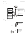
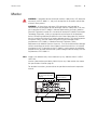
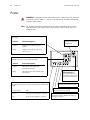
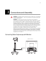
Video Colposcope
Directions for Use
REF 88000A/88001A/89000A/88007/89001A/88007/88002A/88004A/88006A/89006A
Video Colposcope
Directions for Use
REF 88000A/88001A/89000A/88007/89001A/88007/88002A/88004A/88006A/89006A
ii
Welch Allyn Video Colposcope
Copyright 2005 Welch Allyn. All rights are reserved. No one is permitted to reproduce or duplicate, in any
form, this manual or any part thereof without permission from Welch Allyn.
Welch Allyn assumes no responsibility for any injury to anyone, or for any illegal or improper use of the
product, that may result from failure to use this product in accordance with the instructions, cautions,
warnings, or statement of intended use published in this manual.
Welch Allyn® is a registered trademark of Welch Allyn.
For information about any Welch Allyn product, call Welch Allyn Technical Support
:
USA +1 800 535 6663
+1 315 685 4560
Canada +1 800 561 8797
European Call Center +353 46 90 67790
Germany +49 7477 9271 70
Latin America +1 305 669 9003
Singapore +65 6419 8100
United Kingdom +44 207 365 6780
Manual Part Number 880324 Ver. C
Welch Allyn
4341 State Street Road
Skaneateles Falls, NY 13153 USA
www.welchallyn.com
Printed in USA
Australia +61 2 9638 3000
China +86 21 6327 9631
France +33 1 60 09 33 66
Japan +81 3 3219 0071
Netherlands +31 157 505 000
South Africa +27 11 777 7555
Sweden +46 85 853 6551
iii
Contents
1 - Introduction . . . . . . . . . . . . . . . . . . . . . . . . . . . . . . . . . . . . . . . . . . . . . 1
Indications For Use . . . . . . . . . . . . . . . . . . . . . . . . . . . . . . . . . . . . . . . . . . . . . . . . 1
Symbols . . . . . . . . . . . . . . . . . . . . . . . . . . . . . . . . . . . . . . . . . . . . . . . . . . . . . . . . 1
Warnings and Cautions . . . . . . . . . . . . . . . . . . . . . . . . . . . . . . . . . . . . . . . . . . . . . 2
Warnings . . . . . . . . . . . . . . . . . . . . . . . . . . . . . . . . . . . . . . . . . . . . . . . . . . . . 2
Cautions . . . . . . . . . . . . . . . . . . . . . . . . . . . . . . . . . . . . . . . . . . . . . . . . . . . . . 3
2 - Components . . . . . . . . . . . . . . . . . . . . . . . . . . . . . . . . . . . . . . . . . . . . 5
Video Colposcope . . . . . . . . . . . . . . . . . . . . . . . . . . . . . . . . . . . . . . . . . . . . . . . . . 5
Front View. . . . . . . . . . . . . . . . . . . . . . . . . . . . . . . . . . . . . . . . . . . . . . . . . . . . . . . 7
Side Views . . . . . . . . . . . . . . . . . . . . . . . . . . . . . . . . . . . . . . . . . . . . . . . . . . . . . . 8
Back View . . . . . . . . . . . . . . . . . . . . . . . . . . . . . . . . . . . . . . . . . . . . . . . . . . . . . . . 9
Bottom View . . . . . . . . . . . . . . . . . . . . . . . . . . . . . . . . . . . . . . . . . . . . . . . . . . . . . 9
Vertical Stand . . . . . . . . . . . . . . . . . . . . . . . . . . . . . . . . . . . . . . . . . . . . . . . . . . . 10
Swing Arm Stand . . . . . . . . . . . . . . . . . . . . . . . . . . . . . . . . . . . . . . . . . . . . . . . . 10
Monitor . . . . . . . . . . . . . . . . . . . . . . . . . . . . . . . . . . . . . . . . . . . . . . . . . . . . . . . . 11
Printer . . . . . . . . . . . . . . . . . . . . . . . . . . . . . . . . . . . . . . . . . . . . . . . . . . . . . . . . . 12
3 - Connections and Assembly . . . . . . . . . . . . . . . . . . . . . . . . . . . . . . . 13
Connecting Video Colposcope with Monitor . . . . . . . . . . . . . . . . . . . . . . . . . . .
Connecting Video Colposcope with Optional VCR/Video Printer . . . . . . . . . . . .
Assembly . . . . . . . . . . . . . . . . . . . . . . . . . . . . . . . . . . . . . . . . . . . . . . . . . . . . . .
General Precautions . . . . . . . . . . . . . . . . . . . . . . . . . . . . . . . . . . . . . . . . . . .
Video Colposcope. . . . . . . . . . . . . . . . . . . . . . . . . . . . . . . . . . . . . . . . . . . . .
Vertical Stand Assembly. . . . . . . . . . . . . . . . . . . . . . . . . . . . . . . . . . . . . . . .
Swing Arm Stand Assembly. . . . . . . . . . . . . . . . . . . . . . . . . . . . . . . . . . . . .
Setting Up Video Colposcope. . . . . . . . . . . . . . . . . . . . . . . . . . . . . . . . . . . .
13
14
15
15
15
16
16
18
4 - Operation . . . . . . . . . . . . . . . . . . . . . . . . . . . . . . . . . . . . . . . . . . . . . . 19
Power Switch . . . . . . . . . . . . . . . . . . . . . . . . . . . . . . . . . . . . . . . . . . . . . . . . . . .
Lamp Ignition . . . . . . . . . . . . . . . . . . . . . . . . . . . . . . . . . . . . . . . . . . . . . . . . . . .
Focus and Zoom Controls . . . . . . . . . . . . . . . . . . . . . . . . . . . . . . . . . . . . . . . . . .
Mag Index Control . . . . . . . . . . . . . . . . . . . . . . . . . . . . . . . . . . . . . . . . . . . . . . .
Green Filter Control . . . . . . . . . . . . . . . . . . . . . . . . . . . . . . . . . . . . . . . . . . . . . .
Polarization Filter Control . . . . . . . . . . . . . . . . . . . . . . . . . . . . . . . . . . . . . . . . . .
Illumination Beam Director . . . . . . . . . . . . . . . . . . . . . . . . . . . . . . . . . . . . . . . . .
Vertical Height Adjustment Ring (Vertical Colposcope Model Only) . . . . . . . . .
Swing Arm Height Adjustment (Swing Arm Colposcope Model Only) . . . . . . .
Positioning Video Colposcope. . . . . . . . . . . . . . . . . . . . . . . . . . . . . . . . . . . . . . .
19
19
19
20
20
20
20
21
21
21
iv
Contents
Welch Allyn Video Colposcope
Remote Video Functions. . . . . . . . . . . . . . . . . . . . . . . . . . . . . . . . . . . . . . . . . . . 21
5 - Maintenance . . . . . . . . . . . . . . . . . . . . . . . . . . . . . . . . . . . . . . . . . . . 23
Disinfecting Solutions . . . . . . . . . . . . . . . . . . . . . . . . . . . . . . . . . . . . . . . . . . . . .
Video Colposcope Cleaning . . . . . . . . . . . . . . . . . . . . . . . . . . . . . . . . . . . . . . . .
Lens Cleaning . . . . . . . . . . . . . . . . . . . . . . . . . . . . . . . . . . . . . . . . . . . . . . . . . . .
Camera Lens . . . . . . . . . . . . . . . . . . . . . . . . . . . . . . . . . . . . . . . . . . . . . . . .
Illumination Beam Director Lens . . . . . . . . . . . . . . . . . . . . . . . . . . . . . . . . .
Replacing Lamp . . . . . . . . . . . . . . . . . . . . . . . . . . . . . . . . . . . . . . . . . . . . . . . . .
Replacing Fuses . . . . . . . . . . . . . . . . . . . . . . . . . . . . . . . . . . . . . . . . . . . . . . . . .
Troubleshooting . . . . . . . . . . . . . . . . . . . . . . . . . . . . . . . . . . . . . . . . . . . . . . . . .
23
23
23
23
24
24
25
27
6 - Specifications . . . . . . . . . . . . . . . . . . . . . . . . . . . . . . . . . . . . . . . . . . 29
Video Colposcope . . . . . . . . . . . . . . . . . . . . . . . . . . . . . . . . . . . . . . . . . . . . . . . .
Video Monitor . . . . . . . . . . . . . . . . . . . . . . . . . . . . . . . . . . . . . . . . . . . . . . . . . . .
Agency Approvals . . . . . . . . . . . . . . . . . . . . . . . . . . . . . . . . . . . . . . . . . . . . . . . .
Guidance and Manufacturer’s Declaration . . . . . . . . . . . . . . . . . . . . . . . . . . . . .
Emissions and Immunity Information . . . . . . . . . . . . . . . . . . . . . . . . . . . . .
29
30
31
32
32
7 - Service . . . . . . . . . . . . . . . . . . . . . . . . . . . . . . . . . . . . . . . . . . . . . . . . 37
Technical Assistance . . . . . . . . . . . . . . . . . . . . . . . . . . . . . . . . . . . . . . . . . . 37
Service Manual/Spare Parts . . . . . . . . . . . . . . . . . . . . . . . . . . . . . . . . . . . . . 37
Warranty . . . . . . . . . . . . . . . . . . . . . . . . . . . . . . . . . . . . . . . . . . . . . . . . . 39
1
1
Introduction
Thank you for purchasing the Welch Allyn Video Colposcope. Follow the operation and
maintenance instructions found in this manual and your Video Colposcope will provide you
with many years of reliable service. Please read these instructions thoroughly before
attempting to use your new Video Colposcope.
IMPORTANT: The material outlined in this manual should be reviewed and understood
prior to operation of the equipment.
Indications For Use
For examination of the tissues of the vagina, cervix, and external genitalia, to investigate,
by means of magnification, abnormal cervical cytology or suspicious lesions of the lower
female genital tract. Also used for corresponding biopsy and treatment, when indicated.
Symbols
On: Power: Connects to the
low voltage supply.
Off: Power: Disconnects from the
low voltage supply.
Attention: Consult user's
manual for additional
information.
Warning: A warning statement in
this manual identifies a condition or
practice, which if not corrected or
discontinued immediately, could
lead to patient injury, illness, or
death.
High temperatures
Caution: A caution statement in
this manual identifies a condition or
practice, which if not corrected or
discontinued immediately, could
lead to equipment failure,
equipment damage, or data loss.
Risk of fire. Replace fuses as
marked.
High-intensity light
Power supply of unit is
energized whenever power
cord is plugged in.
Type B Equipment
2
Introduction
Welch Allyn Video Colposcope
Warnings and Cautions
Familiarize all operating personnel with the general safety information in this summary.
Specific warnings and cautions are also found throughout this manual.
Warnings
A warning statement in this manual identifies a condition or practice, which if not
corrected or discontinued immediately, could lead to patient injury, illness, or death.
WARNING Users of this equipment should be thoroughly trained in the
appropriate medical procedures. Furthermore, they should take the time to read
and understand these instructions before performing any procedure. They should
also read and understand the instructions for any other equipment used in
conjunction with the Video Colposcope (i.e. electrosurgical generators). Failure to
do so may result in injury to the patient and/or damage to the Video Colposcope.
WARNING The Video Colposcope should not be operated in the presence of
flammable or explosive gases (i.e., anesthetics) or chemicals, or installed in areas
where these materials are commonly used.
WARNING Keep all liquids away from electrical equipment to avoid the
possibility of shock and instrument damage.
WARNING The lamp is extremely bright. DO NOT stare directly into illumination
lens when the lamp is lit.
WARNING Video Colposcope user should adhere to the operating conditions
found in this manual. Otherwise, instrument damage may occur and/or operator/
patient safety may be compromised.
WARNING All signal input and output (I/O) connectors are intended for
connection to only peripheral devices (example: monitor, video printer, VCR, PC,
DV Converter) that are in compliance with IEC 60601-1 (General Requirements for
Safety, Medical Electrical Equipment) or other IEC standards (for example IEC
60950, Information Technology Equipment - Safety) as appropriate to the nature
of the peripheral device. Connecting additional peripherals to the Video
Colposcope may increase the risk associated with chassis or patient leakage
currents. To maintain operator and patient safety, the User should consider the
system leakage current requirements of IEC 60601-1-1 (Medical Electrical
Equipment, Safety Requirements for Medical Electrical Systems). The user
should measure leakage currents accordingly to confirm that no electric shock
hazard exists. An isolation transformer that is in compliance with IEC 60601-1
used to power the additional peripherals may be used to control the system
leakage current to comply with the requirements of IEC 60601-1-1.
WARNING If peripheral devices (example: monitor, video printer, VCR ,other) do
not comply with IEC 60601-1-1 (Medical Electrical Equipment, Safety
Requirements for Medical Electrical systems), they must be kept out of the
patient area (6 feet minimum from patient).
WARNING DO NOT use a converter adapter that will convert the three-prong
AC plug to a two-prong line plug. The power supply in the Video Colposcope will
not be properly grounded and electric shock might result.
Directions for Use
Introduction
WARNING For safety, the Video Colposcope should only be coupled to a
grounded 110-120 VAC hospital-grade outlet (220 - 240 volt, 50 cycle
international).
WARNING The lamp operates at a high temperature. DO NOT attempt to
remove the lamp before allowing it to cool. Allow at least five minutes for the
lamp to cool before replacing. Replace with Welch Allyn lamp #09800-U only.
Cautions
A caution statement in this manual identifies a condition or practice, which if not
corrected or discontinued immediately, could lead to equipment failure, equipment
damage, or data loss.
Caution Federal law restricts sale of this device to, or to the order of, a
physician or other appropriately licensed medical professional.
Caution Occasionally inspect the power cord for signs of cuts, abrasions or
dents.
Caution The Video Colposcope should never be stored or operated in areas
where it could get wet or could be exposed to any environmental conditions like
extreme temperature or humidity, direct sunlight, dust, etc.
Caution All service to the Video Colposcope must be performed by Welch Allyn
or by an authorized repair center.
Caution There are no user servicable parts (other than the lamp and fuses) in
this unit or in its accessories. Any attempt to disassemble and/or repair this unit
will result in voiding of the warranty.
Caution The Video Colposcope is cooled via a fan located in the back of the
unit. The fan draws air in from beneath the Video Colposcope and exhausts the
air out the back of the Video Colposcope. To avoid overheating, verify that the
unit is no less than 6" from a wall.
Caution Do not clean illumination lens with alcohol. Do not touch optical or
illumination lenses except as described in Maintenance section of this manual.
Caution The colposcope can be damaged if the unit is transported while
holding the handle. The unit should be transported by grasping the pole.
Caution Do not sterilize.
Caution Do not spray or allow solution to drip into the air vents.
Caution Do not immerse any part of the unit in cleaning solutions.
3
4
Introduction
Welch Allyn Video Colposcope
5
2
Components
Video Colposcope
88000A
89000A
Video Colposcope and vertical stand
with vertical stand hardware kit:
Video Colposcope and swing arm
stand with swing arm hardware kit:
•
Allen wrench
•
Allen wrench
•
Allen bolt
•
Bolt
•
Mounting washer
•
Spacer
6
Components
Welch Allyn Video Colposcope
All illustrations are for reference only.
88600
S-Video Cable
761076-0
Power Cord
Optional Accessories
09800-U
Replacement Lamp
88500
RS-232 Interface Cable
488307-9
Replacement Fuse (2 required)
88010
Cervical Model
88040
Dust Cover for Vertical Stand
89040
Dust Cover for Swing Arm
Directions for Use
Components
88030
Vertical Stand with Base Only
89030
Swing Arm Stand with Base Only
Monitor. For specifications see “Video Monitor” on
page 30. Contact Welch Allyn for details.
VCR/Printer. Contact Welch Allyn for details.
Image Capture System. Contact Welch Allyn for details.
Note
Only accessories and components indicated in this manual are to be used with
the Welch Allyn Video Colposcope system.
Front View
Illumination Beam
Director Lens. Provides light
for the examination.
Camera Lens. The lens that
establishes the magnification and field
of view.
Illumination Beam Director.
Directs lamp beam.
7
8
Components
Welch Allyn Video Colposcope
Side Views
Green filter LED indicator.
Illuminates if the electronic
green filter is on.
Fine Focus control
button. Pressing < or
> adjusts the focus.
Polarization filter
control. Adjusts the
proportion of glare
removed from the image.
Green filter button. Pressing
turns the electronic green filter
on or off.
FINE
Zoom control button.
Pressing + or - increases or
decreases magnification
accordingly.
Ventilation slots. Allow air to
enter and leave unit, cooling
internal components.
Ventilation slots. Allow
air to enter and leave unit,
cooling internal
components.
Fine Focus control
button. Pressing < or >
adjusts the focus.
Mag button. Displays
magnification index on
screen.
MAG
FINE
INDEX
Zoom control button.
Pressing + or - increases or
decreases magnification
accordingly.
Mag LED indicator. Illuminates if
Mag Index is on.
Directions for Use
Components
Back View
Power switch. Power control
for the Video Colposcope.
Ventilation slots. Allow air to
enter and leave unit, cooling
internal components.
Attachment knob. Fastens
handle to Video Colposcope.
Remote video function buttons.
Allows use of remote printing and
saving functions with appropriate
accessory device.
F
C
V
Video Colposcope handle. For
positioning the colposcope in the proper
up/down, left/right position.
Bottom View
Ventilation slots. Allow
air to enter and leave unit,
cooling internal
components.
Lamp access door. Removes for lamp
replacement. (Note: If door is not properly closed,
interlock power switches will not activate and the
lamp will not start.)
Mounting piece. Allows the Video Colposcope to attach to the stand. On the
swing arm model, the mounting piece is located at the top of the colposcope.
On the vertical stand model, the mounting piece is located at the bottom of the
colposcope.
9
10
Components
Welch Allyn Video Colposcope
Vertical Stand
RS232 interface cable
connector. Couples with RS232 interface cable.
Height adjustment ring. Allows
vertical movement and locking of stand
at desired height;vertical height
adjustment 36”-46” (91.4cm to
116.8cm).
S-Video output. Outputs
S-Video.
Fuse drawer. Opens for
replacement of fuses.
Vertical rolling base stand.
Allows mobility with 5-caster
base, including two locking
casters.
Power supply cord
receptacle. Couples with power
cord, which should be plugged
into a 110-120 VAC hospitalgrade outlet (220-240 volt, 50
cycle international).
Swing Arm Stand
Height adjustment knob.
Allows adjustment of arm tension
and vertical height adjustment
26.5” to 45.5” (67.3 cm to 115.6
cm).
Swing arm rolling base stand.
Allows overhead positioning of
the instrument with 5-caster
weighted base, including two
locking casters; vertical height
29.5” to 49.5” (74.9cm to
125.7cm).
Directions for Use
Components
11
Monitor
WARNING If peripheral devices (example: monitor, video printer, VCR ,other) do
not comply with IEC 60601-1-1, they must be kept out of the patient area (6 feet
minimum from patient).
WARNING All signal input and output (I/O) connectors are intended for
connection to only peripheral devices (example: monitor, video printer, VCR) that
are in compliance with IEC 60601-1 (General Requirements for Safety, Medical
Electrical Equipment) or other IEC standards (for example IEC 60950, Information
Technology Equipment - Safety) as appropriate to the nature of the peripheral
device. Connecting additional peripherals to the Video Colposcope may increase
the risk associated with chassis or patient leakage currents. To maintain operator
and patient safety, the User should consider the system leakage current
requirements of IEC 60601-1-1 (Medical Electrical Equipment, Safety
Requirements for Medical Electrical Systems). The user should measure leakage
currents accordingly to confirm that no electric shock hazard exists. An isolation
transformer that is in compliance with IEC 60601-1 used to power the additional
peripherals may be used to control the system leakage current to comply with the
requirements of IEC 60601-1-1.
Note
Image is for reference only. Actual monitor may vary. Monitor shown is SONY
LMD-1410.
Use the video monitor provided by Welch Allyn or any video monitor that meets
the specifications listed on page 30.
For detailed instructions, please refer to the provided manufacturer’s operation
manual.
LINE A [S-Video composite
(BNC), (4 pin mini-DIN), Audio
(RCA pin)]
PARALLEL REMOTE RGB/COMPONENT
LINE A
IN
IN
OUT
S-VIDEO
VIDEO
PARALLEL REMOTE
(modular connector)
IN
G/Y
OUT
IN
OUT
IN
LINE B OUT
VIDEO
IN
OUT
OUT
B/Pb
~AC IN
IN
AC IN
socket
AUDIO
AUDIO
OUT
LINE B [composite
(BNC), Audio (RCA pin)]
IN
OUT
R/Pr
IN
AUDIO
OUT
RGB/COMPONENT (BNC),
Aduio (RCA pin)
12
Components
Welch Allyn Video Colposcope
Printer
WARNING If peripheral devices (example: monitor, video printer, VCR ,other) do
not comply with IEC 60601-1-1, they must be kept out of the patient area (6 feet
minimum from patient).
Note
For detailed instructions, please refer to the printer operation manual that has
been provided by the manufacturer. Printer shown is SONY UP-20; this is for
reference only.
Input Connectors. To connect the video equipment supplying the
source image.
Connector
Connectable Equipment
S-VIDEO
Equipment with a S-Video (Y/C) output
connector
VIDEO
Equipment with a composite video signal
output connector.
~ AC IN. To connect the
printer to a wall outlet with
the supplied cord.
INPUT
Output Connectors. To connect the video monitor. Refer to “Important
safeguards/notices for use in the medical environments”
REMOTE
1
Connector
Connectable Equipment
S-VIDEO
Video Monitor with a S-Video (Y/C)
separated input connector
VIDEO
Video Monitor with a composite video signal
input connector.
NTSC/PAL (TV) Selector. Set this selector according to the TV system of the
input signal. If you change this setting, turn the printer power off and then back
on again.
Selector position
When
NTSC
NTSC system video equipment is connected.
PAL
PAL system video equipment is connected.
NTSC
S-VIDEO
VIDEO
OUTPUT
S-VIDEO
VIDEO
~ AC IN
RS-2232C
2
PAL
Equipotential Ground
Terminal Connector. To
connect to the equipotential
plug to bring the various parts of
a system to the same potential.
RS-232C Connector. To connect the
Video Colposcope to control the printer.
Remote 2 Connector. To connect an RM-91
Remove Control Unit (not supplied).
Remote 1 Connector. To connect an RM-5500
Remote Control Unit (not supplied) to be used as a
wired remote control unit.
13
3
Connections and Assembly
WARNING If peripheral devices (example: monitor, video printer, VCR ,other) do
not comply with IEC 60601-1-1, they must be kept out of the patient area (6 feet
minimum from patient).
WARNING All signal input and output (I/O) connectors are intended for
connection to only peripheral devices (example: monitor, video printer, VCR) that
are in compliance with IEC 60601-1 (General Requirements for Safety, Medical
Electrical Equipment) or other IEC standards (for example IEC 60950, Information
Technology Equipment - Safety) as appropriate to the nature of the peripheral
device. Connecting additional peripherals to the Video Colposcope may increase
the risk associated with chassis or patient leakage currents. To maintain operator
and patient safety, the User should consider the system leakage current
requirements of IEC 60601-1-1 (Medical Electrical Equipment, Safety
Requirements for Medical Electrical Systems). The user should measure leakage
currents accordingly to confirm that no electric shock hazard exists. An isolation
transformer that is in compliance with IEC 60601-1 used to power the additional
peripherals may be used to control the system leakage current to comply with the
requirements of IEC 60601-1-1.
Connecting Video Colposcope with Monitor
Back Panel of Monitor
PARALLEL REMOTE RGB/COMPONENT
LINE A
IN
IN
OUT
S-VIDEO
VIDEO
IN
G/Y
OUT
IN
OUT
IN
LINE B OUT
VIDEO
IN
OUT
OUT
B/Pb
~AC IN
IN
S-Video Cable to Monitor
Line A S-Video (Y/C) In
AUDIO
AUDIO
OUT
IN
OUT
R/Pr
IN
AUDIO
OUT
14
Connections and Assembly
Welch Allyn Video Colposcope
Connecting Video Colposcope with Optional VCR/Video
Printer
WARNING If peripheral devices (example: monitor, video printer, VCR ,other) do
not comply with IEC 60601-1-1, they must be kept out of the patient area (6 feet
minimum from patient).
Back Panel of Printer
S-Video Cable Out to Monitor
Line A S-Video (Y/C) In
INPUT
REMOTE
1
NTSC
S-VIDEO
VIDEO
OUTPUT
S-VIDEO
VIDEO
~ AC IN
RS-2232C
2
PAL
RS232 Interface Cable
PARALLEL REMOTE RGB/COMPONENT
LINE A
IN
IN
OUT
S-VIDEO
VIDEO
IN
G/Y
OUT
IN
OUT
IN
LINE B OUT
VIDEO
IN
OUT
OUT
B/Pb
~AC IN
IN
AUDIO
AUDIO
OUT
IN
OUT
R/Pr
Back Panel of Monitor
IN
AUDIO
OUT
S-Video Cable to
Printer S-Video In
Directions for Use
Connections and Assembly
15
Assembly
General Precautions
Make sure the unit is always grounded and secure during use. Do not disable power cord
ground connection. Grounding reliability is achieved only when power cord is connected
to a hospital-grade receptacle. Inspect the electrical plug and cord routinely. Do not use if
damaged. Do not use the Video Colposcope in the presence of any flammable
anesthetics.
Do not open the Video Colposcope housing. An electrical shock hazard exists due to high
voltage. There are no user serviceable parts inside the Video Colposcope, except the
lamp.
Note
Opening of the Video Colposcope housing by an unauthorized repair facility will
void the product warranty.
WARNING If peripheral devices (example: monitor, video printer, VCR ,other) do
not comply with IEC 60601-1-1, they must be kept out of the patient area (6 feet
minimum from patient).
WARNING DO NOT use a converter adapter that will convert the three-prong AC
plug to a two-prong line plug. The power supply in the Video Colposcope will not
be properly grounded and electric shock might result.
Caution The Video Colposcope is cooled via a vent fan located in the back of
the unit. The fan draws air in from beneath the Video Colposcope and exhausts
the air out the back of the Video Colposcope. To avoid overheating, verify that the
unit is no less than 6" from a wall.
Caution The colposcope can be damaged if the unit is transported while
holding the handle. The unit should be transported by grasping the pole.
Video Colposcope
Before initial set up of the Video Colposcope, check all components received against the
parts list of components (see Components section of this manual) to verify a complete
set. If parts are missing, please notify Welch Allyn. Review the Nomenclature,
Preparation for Use, Operation, and Maintenance sections to become familiar with the
equipment.
16
Connections and Assembly
Welch Allyn Video Colposcope
Vertical Stand Assembly
The Video Colposcope stand is shipped unassembled. Minimal assembly is required.
1.
Remove the stand and base parts from their cartons.
2. Place base upside down on the floor and insert casters into holes on the bottom of
the base. (Do not place two locking casters next to each other.)
Locking caster
3. Place the base on the floor with casters down. Lock the two locking casters.
4. Place pole into the base, aligning the pin on the flange with the pin hole in the base.
Place bolt, spacer, and washer, oriented as shown, into the pole. Tighten securely
with the enclosed Allen wrench. (The assembly may need to be tilted.)
Washer
Spacer
Hex Bolt
Allen Wrench
Align pin with hole
Before using the Video Colposcope, refer to “Setting Up Video Colposcope” section
of this manual.
Swing Arm Stand Assembly
The Video Colposcope stand is shipped unassembled. Minimal assembly is required.
Note
1.
BASE WEIGHS 58 LBS. YOU MAY REQUIRE ASSISTANCE TO LIFT IT.
To assemble the stand, remove the stand and base parts from the cartons.
Directions for Use
Connections and Assembly
17
Locking caster
2. Place base upside down on the floor and insert casters into holes on the bottom of
the base. (Do not place two locking casters next to each other.)
3. Place the base on the floor with casters down. Lock the two locking casters.
4. Place the vertical pole section of the assembly into the base, aligning the pin on the
flange with the pin hole in the base.
Hex Bolt
Allen Wrench
Align pin with hole
5. Locate the packaged bolt.
6. Place the bolt through the bottom of the pole. (The assembly may need to be tilted.)
7.
Tighten securely with the enclosed Allen wrench.
8. Remove the bolt from the arm of the colposcope assembly and insert it through the
hole near the top of the pole.
9. Position the pole and the arm of the remaining colposcope assembly in close
proximity.
10. Connect the two wire harnesses via their connectors. (This may require assistance
for proper assembly.)
.
11. Bring the colposcope swing arm assembly to the pole while at the same time pushing
the electrical connectors into the colposcope arm.
18
Connections and Assembly
Welch Allyn Video Colposcope
12. Tighten the bolt securely with the enclosed Allen wrench. Be sure not to pinch any of
the electrical wires between the vertical pole and arm of the colposcope assembly.
13. Before using the Video Colposcope, refer to Setting Up Video Colposcope section of
this manual.
Setting Up Video Colposcope
1.
Connect the power cord to the power cord receptacle in the power supply located on
the Video Colposcope stand.
2. Plug the other end of the power cord into a properly grounded 110-120 volt AC outlet
(220-240 volt, 50 cycle for international).
3. Connect the S-Video cable to the S-Video output on the side of the power supply
located on the Video Colposcope stand.
4. Connect the other end of the S-Video cable into the Line A connector S-Video (Y/C) on
the back of the monitor.
5. Plug the monitor into a properly grounded 110-120 volt AC outlet (220-240 volt, 50
cycle for international).
RS232 output
S-Video output
Power Cord
19
4
Operation
Power Switch
With the power cord connected to a properly grounded outlet, and the S-video cable
connected to the Video Colposcope and monitor, activate the power switch on the handle
of the Video Colposcope.
Lamp Ignition
Once the Video Colposcope's power switch has been activated, the lamp will ignite. The
lamp requires approximately 11 seconds to warm up.
Focus and Zoom Controls
Once the power switch has been activated, the Video Colposcope will execute a setup
procedure, ending in the low magnification setting, or 4.5x. To obtain coarse focus,
position the distal end of the Video Colposcope approximately 300mm (12”) from the
target. Adjust the Video Colposcope by moving the stand (for vertical stand), or the arm
(for the swing arm stand), until the picture is in focus. Press the + on one of the zoom
controls until maximum magnification is obtained, and readjust the position of the stand
or the swing arm until the picture is in focus. Fine focus, in either direction, is provided by
the focus controls once coarse focus has been achieved. After coarse focus is achieved at
maximum magnification, zoom control can be set to a desired lower magnification by
pressing either zoom control. Focus will be maintained throughout the entire
magnification range once these steps have been completed if the Video Colposcope or
target is not moved.
Note
The setup (nominal) setting of the focus controls can be recovered by pressing
one of the zoom + controls for 4 seconds after maximum magnification has been
achieved.
20
Operation
Welch Allyn Video Colposcope
Mag Index Control
Note
Pressing the scan button on the monitor or activating this menu option sets the
display size to -3% “under” image scan size and alters the size of the image on
the screen, making the magnification index displayed inaccurate. Activating the
button or mem option briefly displays the word “under” on the monitor screen
and a red light displays on the scan button. To change the scan size back to
normal, press the scan button again and the word “over” briefly appears on the
monitor screen. This is the normal setting.
Activate the magnification index button by pressing the blue button located on the right
side of the colposcope (See “Side Views” on page 8.). The Mag Index refers to
magnification relative to a 14” monitor. Deactivate the magnification index by pressing the
mag index control again.
To determine the magnification*, multiply the mag index by the number in the table
below.
DISPLAY DEVICE
NUMBER BY WHICH TO MULTIPLY MAG INDEX
Sony 14” Monitor, model
LMD1410
1.0
EXAMPLE: Mag. Index on screen
5
EXAMPLE: Magnification
5
*Magnification is the approximate size of an object displayed on a display device (monitor,
video print, etc.) divided by the actual size of the object.
Green Filter Control
Press the green filter button on the left side of the video colposcope (Figure on page 8) to
activate the electronic green filter. Press the green filter button again to deactive the filter.
Polarization Filter Control
The Polarization Filter control can be rotated to reduce glare from the image as desired.
The filter is completely engaged (minimum glare) when the control is fully rotated to the
left. The filter can be disengaged by returning the Polarization Filter control to the full right
hand position.
Illumination Beam Director
The illumination beam director can be rotated up to 45° clockwise or counterclockwise to
better illuminate the examination area. To rotate the director, grasp the flat sides and twist
in either direction as desired. The illumination beam director moves with some resistance.
This helps to hold it securely in the desired position. The center position can be recovered
by returning the director to the detent position.
Directions for Use
Operation
Vertical Height Adjustment Ring
21
(Vertical Colposcope Model Only)
The height of the vertical stand can be adjusted by rotating the black height adjustment
ring, located on the pole of the stand, counterclockwise. Once the ring has been
loosened, adjust the pole to the desired height and then tighten the ring again by rotating
it clockwise.
Swing Arm Height Adjustment
(Swing Arm Colposcope Model Only)
Adjust the height of the swing arm stand by loosening the height adjustment knob
located on the arm of the stand. The swing arm can then be moved to the desired
position. After moving the arm, tighten knob securely by rotating clockwise. The desired
drag can be obtained by adjusting this knob either clockwise or counterclockwise.
Positioning Video Colposcope
The video colposcope can be angled up and down and left and right. To change the up/
down tilt angle, loosen the knob located on the tilt axis. The video colposcope can then
be tilted as necessary. To change the horizontal angle, loosen the knob located on the
support shaft. The drag of either knob can be set by loosening or tightening as necessary.
Remote Video Functions
The handle of the video colposcope contains three buttons that control three video
functions. These functions, provided by a remote video printer or Welch Allyn software
program, are Freeze, Print, and Toggle. (See “Operation” on page 19. of this manual for
connecting the printer to the video colposcope.)
•
Pressing the freeze (“F”) button stores a new image in memory. The frozen image is
displayed on the monitor or PC.
•
Pressing the copy (“C”) button prints/saves the image displayed on the monitor. If
live video is displayed, the image visible when the button was pressed will be printed/
saved.
•
Pressing the video (“V”) button changes the display from printer memory (frozen
image) to live video, or from live video to printer memory (frozen image), depending
on the current mode.
22
Operation
Welch Allyn Video Colposcope
23
5
Maintenance
Disinfecting Solutions
The disinfecting solutions listed below are safe for cleaning the housing of the video
colposcope if used according to the manufacturer’s instructions for cleaning and
disinfecting, and in accordance with procedures detailed in the cleaning section of this
manual.
•
70% isopropyl alcohol
•
10% mild bleach solution
•
10% Wescodyne
Note
References to brand names are not endorsements of their efficacy as disinfecting
solutions. However, tests have shown these solutions to be compatible with
Welch Allyn colposcopes, providing the manufacturers' directions are followed.
Video Colposcope Cleaning
Turn the power switch off and unplug the power cord from the electrical outlet prior to
cleaning.
The video colposcope housing can be wiped down with a cloth dampened slightly with a
mild solution of disinfectant. Be careful not to allow the plug prongs to get wet. Also be
careful not to allow the camera lens or lamp lens to get wet.
Caution Do not sterilize.
Caution Do not spray or allow solution to drip into the air vents.
Caution Do not immerse any part of the unit in cleaning solutions.
Lens Cleaning
Camera Lens
Clean the camera lens with isopropyl alcohol or any commercial lens cleaner.
24
Maintenance
Welch Allyn Video Colposcope
Illumination Beam Director Lens
Caution DO NOT clean illumination beam director lens with alcohol. DO NOT
touch the camera or illumination lenses except as described in Maintenance
section of this manual.
Clean the illumiantion beam director lens with a cloth dampened slightly with warm water
and mild detergent.
Replacing Lamp
WARNING The lamp operates at a high temperature. DO NOT attempt to
remove the lamp before allowing it to cool. Allow at least five minutes for the
lamp to cool before replacing. Replace with Welch Allyn lamp #09800-U only.
1.
Turn the power switch off and unplug the power cord from the electrical outlet.
2. Holding the video colposcope as shown, turn the knob located at the back of the
handle counterclockwise and unscrew and remove the video colposcope from the
handle.
3. Place the unit on a suitable work surface. Slide the lamp access door away from the
housing as shown until the door is completely removed.
4. Unplug the lamp from the electrical connector.
Directions for Use
Maintenance
25
5. Push the retainer spring toward the back ofthe colposcope and remove the lamp from
its housing.
6. Remove a Welch Allyn replacement lamp # 09800-U from its package. Do not touch
the lamp itself or the interior reflective surface of the lamp. Skin oils will cause
premature lamp failure. Hold lamp by the outside of the reflector or the connector
only. Remove any grease or fingerprints with a clean cotton swab moistened with
alcohol. Do not leave any lint on the lamp.
7.
Holding the retainer spring as in Step 5, slide the new lamp into the lamp housing so
that the lamp's alignment pin engages the alignment slot in the lamp holder. (Make
sure lamp is properly seated and snaps into place.)
8. Plug the electrical connector onto the new lamp.
9. Slide the lamp access door securely back into place, reversing the process described
in Step 3 above.
10. Place the video colposcope back into the handle, making sure the power connector is
engaged.
11. Rotate the knob clockwise until snug.
12. Plug the power cord back into the electrical outlet.
Replacing Fuses
Two fuses are located in slots adjacent to the power supply cord receptacle on the side of
the power supply housing. This housing is attached to the pole of the video colposcope
stand.
1.
To replace a blown fuse, remove the fuse holder by pressing the tab and pulling the
holder out of the power supply.
26
Maintenance
Welch Allyn Video Colposcope
Tab
2. Pull out and remove the blown fuse from the fuse holder.
3. Replace with new fuses # T1.00L-250V 1A Time lag/Low Breaking Capacity (Welch
Allyn Part # 488307-9).
4. Reinsert the fuse holder by pressing until it snaps into place.
Directions for Use
Maintenance
Troubleshooting
Condition
Check
Power does not come on. Power Cord
No image on monitor.
Lamp will not light.
Printer does not respond
properly to handle
buttons.
Action
Check connections at power supply and
wall outlet.
Attachment of unit to handle
Check colposcope unit’s alignment with
handle.
Attachment of unit to handle and door to
unit
Make sure lamp access door and handle
are properly attached.
Fuses
Remove fuse panel & replace blown fuse
with T1.00L 250V 1A time lag (Welch Allyn
part number # 488307-9).
Wall outlet
Plug the power cord into a wall outlet
known to work.
Monitor/other peripheral devices
Make sure power is on for all devices.
Cable connections
Make sure all video cables are connected
properly.
Monitor input selection
Make sure correct input selection is made
on the front panel.
Lamp housing
Make sure lamp assembly is installed
properly.
Lamp
Replace lamp.
Lamp access door
Make sure lamp access door is properly
closed.
Power cord and printer
Unplug power cord from wall outlet, then
plug cord back in to outlet. At the same
time, turn printer off and then on again.
Printer
Make sure printer is on and is properly
connected.
27
28
Maintenance
Welch Allyn Video Colposcope
29
6
Specifications
Video Colposcope
Item
Power requirements
Dimensions
Weight
Video Colposcope
Specifications
Operating environment
Illumination
Cooling method
Specification
Technical Data
Voltage
115VAC domestic
220-240VAC international
Frequency
50/60Hz
Current
1.0 Amp
Vertical Stand
Low: 36.0”, high: 46.0”
(91.4 cm to 116.8 cm)
Swing arm stand
Low: 29.5”, high: 49.5”
(74.9 cm to 125.7 cm)
Optical centerline to swing arm bottom
15.0” (38.1 cm)
Colposcope HxWxD (excluding handles)
8.25” x 5.75” x 3.37”
(21.0 cm x 14.6 cm x 8.6 cm)
Colposcope
3.1 lbs (1.4 kg)
Vertical Stand
25 lbs (11.3 kg)
Swing arm stand
80 lbs (36.3 kg)
Focal length
300 mm (12”)
Magnification (relative to a 14” monitor)
4.5x - 30x (typ.)
Field of view
66mm - 14mm
Depth of field
112mm - 5mm
Ambient temperature
50° F (+10° C) to 104°F (+40° C)
Relative humidity
95% max
Atmospheric pressure
70kPa to 110kPa
Lamp type
21 Watt metal halide arc
Lamp life
750 hrs @ 1 hr per start
Brightness adjustment
Automatic electronic shutter
Lamp
Welch Allyn part no. 09800-U
Lamp voltage
60 volts
Forced air via fan
30
Specifications
Welch Allyn Video Colposcope
Item
Specification
Technical Data
Color system
Color mosaic CCD
Video output
S-Video (Y/C)
Remote Control
RS-232
9-Pin D Female Connector
Transport/Storage
environment
Ambient temperature
-40°F (-40°C) to 120° F (+50° C)
Relative humidity
95% max.
Fuses
T1.00L-250V
(Welch Allyn part # 488307-9)
1 Amp time lag,
low breaking capacity
Classification
Electro medical equipment
FDA Class I equipment
Patents
This product is covered by the following patents:
5,083,059; 5,117,154; 5,138,228; 5,144,201; 5,291,100; D391,360, D395,084; 5,840,012;
5,879,286; D416,088; 6,068,593; 6,147,705.
Patents pending
Video Monitor
Item
Specification
Technical Data
Color Video Monitor
Resolution
-minimum specifications Video Interface
User Controls
Display Aspect Ratio
640 x 480 pixels or greater
S-video input
Color, brightness, contrast
4:3
Color Video Monitor
-regulatory compliance
Product safety
Conformance to local requirements,
examples: UL 6500; CE 60065; IEC 60065;
CAN/CSA E60065-00; other.
Electromagnetic compatibility (EMC)
Conformance to local requirements,
examples: USA FCC Part 15; Canada
ICES-003; CE EN55103-1 & EN55013-2;
Japan VCCI; AS/NZS CISPR22; other.
Directions For Use
Specifications
Agency Approvals
Conforms to: UL 2601-1
Certified to: CAN/CSA C22.2 No. 601.1-M90
IEC 601-1
EN60601-1
EN/IEC 60601-1-2
The CE mark on this product indicates it has been tested to and conforms with the
provisions noted in the 93/42/EEC Medical Device Directive.
EC REP
Authorized EC Representative:
European Regulatory Manager
Welch Allyn, Ltd.
Navan Business Park
Dublin Road
Navan, County Meath, Republic of Ireland
Tel +353 46 90 67700
Fax +353 46 90 67756
31
32
Specifications
Welch Allyn Video Colposcope
Guidance and Manufacturer’s Declaration
Emissions and Immunity Information
Electromagnetic Emissions
The REF 880 and 890 Series Video Colposcope is intended for use in the electromagnetic environment specified below. The customer or user of
the REF 880 and 890 Series Video Colposcope should assure that it is used in such an environment.
Emissions Test
Compliance
Electromagnetic Environment - Guidance
RF emissions
Group 1
The REF 880 and 890 Series Video Colposcope uses RF energy only for its internal
function. Therefore, its RF emissions are very low and are not likely to cause any
interference in nearby electronic equipment.
Class B
The REF 880 and 890 Series Video Colposcope is suitable for use in all establishments,
including domestic establishments and those directly connected to the public
low-voltage power supply network that supplies buildings used for domestic purposes.
CISPR 11
RF emissions
CISPR 11
Harmonic emissions
Class A
IEC 61000-3-2
Voltage fluctuations/
flicker emissions
IEC 61000-3-3
Complies
Directions For Use
Specifications
33
Electromagnetic Immunity
The REF 880 and 890 Series Video Colposcope is intended for use in the electromagnetic environment specified below. The customer or user of
the REF 880 and 890 Series Video Colposcope should assure that it is used in such an environment.
Immunity Test
IEC 60601
Test Level
Compliance Level
Electromagnetic Environment - Guidance
Electrostatic discharge
(ESD)
± 6 kV contact
± 6 kV contact
± 8 kV air
± 8 kV air
Floors should be wood, concrete, or ceramic tile. If floors are
covered with synthetic material, the relative humidity should
be at least 30%.
Electrical fast transient/ ±2 kV for power supply
burst
lines
±2 kV for power supply
lines
Mains power quality should be that of a typical commercial or
hospital environment.
IEC 61000-4-4
±1 kV for input/output
lines
±1 kV for input/output
lines
Surge
±1 kV differential mode
±1 kV differential mode
IEC 61000-4-5
±2 kV common mode
±2 kV common mode
Voltage dips, short
interruptions, and
voltage variations on
power supply input
lines.
>95% dip in 0.5 cycle
>95% dip in 0.5 cycle
60% dip in 5 cycles
60% dip in 5 cycles
30% dip for 25 cycles
30% dip for 25 cycles
IEC 61000-4-11
>95% dip in 5 seconds
>95% dip in 5 seconds
Power frequency
(50/60Hz)
magnetic field
3 A/m
3 A/m
IEC 61000-4-2
IEC 61000-4-8
Mains power quality should be that of a typical commercial or
hospital environment.
Mains power quality should be that of a typical commercial or
hospital environment. If the user of the REF 880 and 890
Series Video Colposcope requires continued operation during
power mains interruptions, it is recommended that the REF
880 and 890 Series Video Colposcope be powered from an
uninterruptible power supply or battery.
Power frequency magnetic fields should be at levels
characteristic of a typical location in a typical commercial or
hospital environment.
34
Specifications
Welch Allyn Video Colposcope
Electromagnetic Immunity
The REF 880 and 890 Series Video Colposcope is intended for use in the electromagnetic environment specified below. The customer or user of
the REF 880 and 890 Series Video Colposcope should assure that it is used in such an environment.
Immunity Test
IEC 60601
Test Level
Compliance Electromagnetic Environment - Guidance
Level
Portable and mobile RF communications equipment should be used no closer
to any part of the Video Colposcope, including cables, than the
recommended separation distance calculated from the equation applicable
to the frequency of the transmitter.
Recommended separation distance
Conducted RF
IEC 61000-4-6
3 Vrms
150 kHz to 80 MHz
3 Vrms
d = (1.17) P
Radiated RF
IEC 61000-4-3
3 V/m
80 MHz to 2.5 GHz
3 V/m
d = (1.17) P 80 MHz to 800 MHz
d = (2.33) P 800 MHz to 2.5 GHz
where P is the maximum output power rating of the transmitter in watts (W)
according to the transmitter manufacturer and d is the recommended
separation distance in metres (m).
Field strengths from fixed RF transmitters, as determined by an
electromagnetic site survey,a should be less than the compliance level in
each frequency range.b
Interference may occur in the vicinity of equipment marked with the
following symbol:
Note 1: At 80 MHz and 800 MHz, the higher frequency range applies.
Note 2: These guidelines may not apply in all situations. Electromagnetic propagation is affected by absorption and reflection from structures,
objects, and people.
a
Field strengths from fixed transmitters, such as base stations for radio (cellular/cordless) telephones and land mobile radios, amateur radio,
AM and FM radio broadcast and TV broadcast cannot be predicted theoretically with accuracy. To assess the electromagnetic environment due
to fixed RF transmitters, an electromagnetic site survey should be considered. If the measured field strength in the location in which the REF
880 and 890 Series Video Colposcope is used exceeds the applicable RF compliance level above, the Video Colposcope should be observed to
verify normal operation. If abnormal performance is observed, additional measures may be necessary, such as reorienting or relocating the
Video Colposcope.
b
Over the frequency range 150 kHz to 80 MHz, field strengths should be less than 3 V/m.
Directions For Use
Specifications
35
Recommended Separation Distances Between Portable and Mobile RF Communications Equipment and the Video Colposcope
The REF 880 and 890 Series Video Colposcope is intended for use in an electromagnetic environment in which radiated RF disturbances are
controlled. The customer or user of the REF 880 and 890 Series Video Colposcope can help prevent electromagnetic interference by maintaining
a minimum distance between portable and mobile RF communications equipment (transmitters) and the REF 880 and 890 Series Video
Colposcope as recommended below, according to the maximum output power of the communications equipment.
Separation Distance According to Frequency of Transmitter (m)
Rated Max. Output
Power of Transmitter
(W)
150 kHz to 80 MHz
80 MHz to 800 MHz
800 MHz to 2.5 GHz
d = (1.17) P
d = (1.17) P
d = (2.33) P
0.01
0.11667
0.11667
0.23333
0.1
0.36894
0.36894
0.73785
1
1.1667
1.1667
2.3333
10
3.6894
3.6894
7.3785
100
11.667
11.667
23.3333
For transmitters rated at a maximum output power not listed above, the recommended separation distance d in meters (m) can be estimated
using the equation applicable to the frequency of the transmitter, where P is the maximum output power rating of the transmitter in watts (W)
according to the transmitter manufacturer.
Note 1: At 80 MHz and 800 MHz, the separation distance for the higher frequency range applies.
Note 2: These guidelines may not apply in all situations. Electromagnetic propagation is affected by absorption and reflection from structures,
objects, and people.
36
Specifications
Welch Allyn Video Colposcope
37
7
Service
Caution Unauthorized repairs will void the warranty.
A Welch Allyn Service Center must perform all repairs on products under warranty.
Qualified electronics personnel or a Welch Allyn Service Center should repair products out
of warranty.
Technical Assistance
If you have an equipment problem that you cannot resolve call the Welch Allyn Technical
Support center nearest you (page ii) on normal business days.
If you are advised to return a product to Welch Allyn for repair or routine maintenance,
schedule the repair with the service center nearest you. The part and serial numbers are
located on the housing of the colposcope near the fan. Remove the colposcope from the
handle to locate these numbers
Before returning a product for repair, you must obtain authorization from Welch Allyn.
Service personnel will give you a Service Notification number. Please note this number on
the outside of your shipping box. Returns without a Service Notification number will not
be accepted for delivery.
Service Manual/Spare Parts
The Service Manual is a comprehensive guide to troubleshooting, service, and repair
available by request to qualified electronics personnel.
Also included with the Service Manual is a complete spare parts list. Order spare parts
from your local Welch Allyn Service Center.
38
Service
Welch Allyn Video Colposcope
39
Warranty
Welch Allyn warrants Video Colposcope, when new, to be free of defects in material and
workmanship and to perform in accordance with manufacturer's specifications for a
period of one year from the date of purchase from Welch Allyn or its authorized
distributors or agents. Welch Allyn will either repair or replace any components found to
be defective or at variance from manufacturer's specifications within this time at no cost
to the customer. It shall be the purchaser's responsibility to return Video Colposcope to
Welch Allyn or an authorized distributor, agent, or service representative. This warranty
does not include the lamp, breakage or failure due to tampering, misuse, neglect,
accidents, modification, or shipping. This warranty is also void if the instrument is not
used in accordance with manufacturer's recommendations or if repaired by other than
Welch Allyn or an authorized agent. Purchase date determines warranty requirements. No
other express warranty is given.
Remember to submit the instrument registration/warranty card for warranty validation.
Complete the information and mail the pre-addressed card to Welch Allyn.
40
Warranty
Welch Allyn Video Colposcope
4341 State Street Road
Skaneateles Falls, NY 13153, U.S.A.
Tel.: 1-800-535-6663
Fax: 1-315-685-3361
www.welchallyn.com
Printed in the USA
880324 Ver. C