1
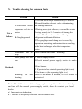
Swimming Pool Heat Pump
INSTALLATION AND USER MANUAL
Contents
I.
Use ........................................................................................................... 17
II.
Features .................................................................................................... 17
III. Technical Specifications........................................................................... 18
IV. Dimensions .............................................................................................. 19
V.
Installation Instructions............................................................................ 20
VI. Instructions for Use.................................................................................. 23
VII. Testing...................................................................................................... 25
VIII. Be Careful ................................................................................................ 26
IX. Maintenance............................................................................................. 28
X.
Trouble shooting for common faults........................................................ 29
Thank your choosing our product and your trust in our company.
To help you get maximum benefit from this product, please read this
instruction manual carefully and operate strictly according to the instructions
before starting the machine; otherwise, the machine may be damaged or cause
you unnecessary harm.
I.
Use
1- This heat pump will efficiently and economically set the water temperature
for your swimming pool enhancing you comfort and pleasure.
2- The user chooses from the specifications to optimize the heating capacity to
best suit their needs (please refer to technical specifications table).
II. Features
1234567-
Highly efficient titanium heat exchanger.
Sensitive and accurate temperature control display.
High-and low-pressure protection.
Below low temperature circuit-breaker.
Automatic defrost Temperature setting.
Internationally known compressor.
Easy installation and operation.
III. Technical Specifications
Model
GP00
GP01
GP02
GP03
GP04
GP05
GP06
GP07
Performance Condition: Air 26℃
℃, Water 26℃
℃
Heating capacity
3.6
5
7
10
13
17
25
26
5.2
5.3
6.3
6.2
6.3
6.2
6.4
6.5
KW
C.O.P.
Performance Condition: Air 15℃
℃, Water 26℃
℃
Heating capacity
2.7
3.7
5
7
9
12
16.5
17
4.1
4.3
4.5
4.4
4.5
4.5
4.5
4.7
2.5
3
3-4
4-6
5-7
6.5-8.5
8-10
8-10
KW
C.O.P.
Advised Water Flux
m³/h
380-415V/3
Power supply
220-240V/1Ph/50Hz
Ph/50Hz
Rated power
Kw
Rated current A
0.66
0.86
1.11
1.59
2
2.67
3.67
3.62
3
3.9
5.0
7.2
9.1
12.1
16.7
5.5
Water pipe in-out
spec
50
mm
Water pipe in-out
48
spec(For UK) mm
Net weight / Gross
weight
31/36
35/40
45/50
52/57
66/70
85/93
127/137
127/137
Kg
Notice:
1- This Heat Pump can work well between 0℃~+43℃ air temperature;
efficiency will not be guaranteed out of this range. Please take into
consideration that the pool heater performances may vary under different
conditions. Consult your Pool specialist.
2- We reserve the right to make improvements periodically without further
notice. For details please refer to the cover-plate on the Heat Pump.
IV. Dimensions
A
B
C
D
E
F
G
H
GP00
275
395
266
300
641
260
73
493
GP01
275
400
267
300
755
200
80
505
GP02
330
580
285
350
930
200
88
550
GP03
330
580
285
350
930
280
88
550
GP04
330
650
300
350
1000
280
88
630
GP05
330
650
300
350
1000
280
88
630
GP06
438
770
425
470
1120
350
88
950
GP07
438
810
425
470
1180
600
88
950
※ Above data is subject to modification without notice.
Note:
The diagram above is for the dimensions of the Heat Pump, for technician’s
layout reference only. We reserve the right to make improvements periodically
without further notice.
V. Installation Instructions
1- Schema for plumbing the water pipes
(Please note: This schematic layout of the pipes is only for reference.).
SCHEMA 2: HEAT PUMP Plumbing
2- Electrical Wiring Diagram
Note:The swimming pool heater must be connected to the
earth rod.
Options for circuit breakers and wire specs
MODEL
Rated Current A
GP00
GP01
GP02
GP03
GP04
GP05
GP06
GP07
6
15
15
20
20
25
40
15
30
30
30
30
30
30
30
30
7
15
15
20
20
25
40
15
3×1.5
3×2.5
3×2.5
3×2.5
3×2.5
3×4
3×6
5×2.5
3×0.5
3×0.5
3×0.5
3×0.5
3×0.5
3×0.5
3×0.5
3×0.5
Breaker Rated Residual Action
Current mA
Fuse
A
Power Cord
Signal cable
(mm2)
2
(mm )
※ Above data is subject to modification without notice.
Note: The above data is adapted to power cord ≤ 10 meters from the power
supply .If power cord is ﹥10 meters away, the wire diameter must be
increased. The signal cable can be extended to 50 meters at most.
3- Installation instructions and requirements
The swimming pool heater must be installed by a professional. The Public is
not qualified to install by themselves for health and safety reasons.
A. Installation
1) The swimming pool heater should be installed in a place with good
ventilation;
2) The frame must be fixed by bolts (M10) to a concrete foundation or brackets.
The concrete foundation must be solid and fast; the bracket must be strong and
treated against rust.
3) Please don’t place objects that might block air flow in front of or behind the
Heat Pump. The Heat Pump must stand at least 50 cm from any structure or
obstacle otherwise the efficiency of the heater will be reduced or even stopped.
4) The machine needs a circulation pump (supplied by the user). The
recommended pump flow: refer to Technical Specs, Max. lift ≥10m.
5) When the machine is running, there will be condensation water discharged
from the bottom of the unit and should go to drain. Please hold the drainage
nozzle (accessory) into the hole and clip it well, and then connect a pipe to
drain the condensation water out.
B.Wiring
B.
1) Connect to the appropriate power supply; the voltage should comply with
the rated voltage of the products.
2) Earth the machine.
3) Wiring must be handled by a professional technician according to the
circuit diagram.
4) Set the Earth-leakage protector according to the local code for wiring
(leakage operating current ≤ 30mA).
5) The layout of power cable and signal cable should be separated.
C.
.Switch on after finishing and double-checking all wiring.
VI. Instructions for Use
Pictograms on the LED screen
CLOCK
HEAT
TIME ON
TIME OFF
1.
. Use of the Display Panel
A. The display panel shows Time when the machine is off;
B. The display panel shows Temperature of the swimming pool water when
the machine is on.
2.
. Water temperature setting
A. Available whether the machine is on or off;
B. Press the key
or
to set water temperature. The display panel
indicates a flashing Temp. Press
or
to adjust to your required
water temp.
C. 5 seconds later, the display panels will return to the normal mode.
3.
. Time setting
A. Available whether the machine is on or off;
B. Press
press
key to set time. When the clock on the screen is flashing,
again to set hour. Use
flashing stops, press
After adjusting, press
and
to set minute Use
to adjust. Before the
and
to adjust.
and water temperature will be seen. 30
seconds later, the display panel will be return the normal mode.
4.
. Timer on and off
A. Press
to set timer on. When the indicator light is on and the
time is flashing, press
again to set hour. Use
adjust. Before the flashing stops, press
and
to set minute Use
to
and
to adjust. After adjusting, press “TIMER ON” and water
temperature will be seen. 30 seconds later , the display panel will return
to the normal mode;
to set timer off. When the indicator light is on and the
B. Press
time is flashing, press
again to set hour. Use
adjust. Before the flashing stops, press
and
to adjust. After adjusting, press
and
to
to set minutes. Use
and water temperature
will be seen. 30 seconds later, the display panel will return to the normal
mode;
C. Cancel timer on and off
Press
or
flashing, press
to cancel timer on and off. When the number is
. When timer indicator light is off and LED shows
water temperature, the timer on and off is canceled. 30 seconds later, the
display panel will return to the normal mode.
VII.
Testing
1.Inspection before use
A.Check the installation of the plumbing installation and the Heat Pump
against the Heat Pump Plumbing schema.
B.Check the electric wiring according to the electrical wiring and earthing
diagrams.
C.Make sure that the mains power is swithched off.
D.Check the temperature setting.
E.Check the air intake and outlet.
2.Trial
A. Please start the pump before the heat pump and turn it off after the heat
pump, so there is water running through the system throughout operation
hours.
B.The user should start the pump, making sure the water pressure is correct;
set the desired temperature on the thermostat, and then switch on the power
supply.
C.In order to protect the swimming pool heater, the Heat Pump is equipped
with a time lag starting function, when starting the Heat Pump, the blower
will run 1 minute before the compressor;
D.After the swimming pool heater starts up, check for any abnormal noise
from the Heat Pump.
VIII.
Be Careful
1. Attention
A. To set the desired temperature in order to get comfortable water temperature;
this will avoid overheating or overcooling;
B. Please don’t stack objects that can block air flow near intake or outlet area,
the Heat Pump’s efficiency may be reduced or even stopped;
C. Please don’t put hands into the outlet of the swimming pool heater, and
don’t remove the screen of the fan at any time;
D. If there are suspect conditions such as noise, smell, smoke and electrical
leakage, please switch off the machine immediately and contact the local
dealer. Don’t try to repair it yourself;
E. Do not use or stock combustible gas or liquid such as thinners, paint and
fuel near the Heat Pump to avoid fire;
F. In order to optimize the heating effect, please install heat preservation
insulation on pipes between swimming pool and the heater. When the Heat
Pump is working please use a recommended cover on the swimming pool
to avoid heat loss through evaporation;
G . The Heat Pump should be placed ≤10m of the swimming pool, or the
heating effect of the heater cannot be ensured;
H. This series of Heat Pumps can achieve high efficiency between the air
temperatures of +15℃~+25℃.
I. In case a power cut during operation, the heat pump will stop, and will start
up automatically when the the power resumes.
2. Safety
A.Please keep the main power supply switch far away from the children;
B.Please switch off the main power supply during lightning and stormy
weather to prevent damage caused by lightning;
C.If the Heat Pump is not in use for a long time, please cut off the power
supply and drain water out of the Heat Pump by opening the tap of inlet
pipe.
IX. Maintenance
A.“Cut off” power supply of the heater before any examination and repair;
B. In winter season when you don’t swim:
a)
Cut off power supply to prevent any machine damage
b)
Drain water clear of the machine.
!!Important:
Unscrew the water nozzle of inlet pipe to
let the water flow out.
When the water in machine freezes in
winter season, the titanium heat exchanger
may be damaged.
c)
Cover the Heat Pump to avoid dirt entering
C.Please clean this Heat Pump with household detergents or clean water,
NEVER with gasoline, thinners, or any similar petrol products;
D.Check bolts, cables and connections regularly.
X. Trouble shooting for common faults
Problem
Not a
failure
Reason
A.Noticeable White
vaporous cold air or
water
B.Gurgling sound
A.The fan motor stops automatically for defrost.
B.Sound from the solenoid valve when starting
and ending of defrost.
C.During use or just after use, a sound like water
flowing, usually in 2~3 minutes of starting the
machine.This Sound comes from flowing
refrigerant or dehumidification.
D.The gurgling sound during use is caused by
expansion on heating and contraction on cooling
of the heat exchanger when the temperature
varies.
Automatic start or
stop
Check whether the timer is working.
Heat pump does not
run
A. Power supply failure
B.Check manual power supply switch to make
sure it is on.
C.Fuse burned.
D. If protector has started (operating light is on)
E. Set timer on (the operating light is on)
Running
heating
Check if the intake is blocked, or if the outlet is
obstructed.
Recheck
but
not
Note: If the following conditions happen, please stop the machine immediately,
and turn off the manual power supply switch, then the contact your local
dealer.
a)Inaccurate switch action;
b)The fuse is frequently broken or circuit breaker acts.
Failure code
NO.
1
2
Failure code
EE 1
EE 2
Failure description
High pressure protection
Low pressure protection
3
EE 3
Low water pressure protection
4
EE 4
5
PP 1
A.1 phase machine: failure connection due to
loose wire terminal of PROT2 on the PC
board;
B.3 phase sequence protection.
Swimming pool heat pump sensor failure
6
PP 2
Exhaust sensor failure
7
PP 3
Coil pipe sensor failure
8
PP 4
Intake pipe sensor failure
9
PP 5
Air temperature sensor failure
10
PP 6
Compressor exhaust
11
PP 7
When the air temperature < 0℃, auto stop
protection (Not Failure )
overload protection