1
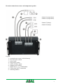
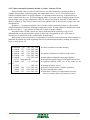
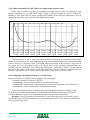
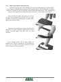
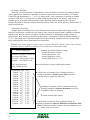
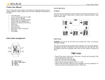
ATP-02 en ATP-02C User manual ATAL B.V. Ampèrestraat 35-37 NL-1446 TR PURMEREND Postbus 783 NL-1440 AT PURMEREND T (+31) 0299 630 610 F (+31) 0299 630 611 E [email protected] I www.atal.nl CONTENT 1.0 Basic recorder features ....................................................................................................... 3 2.0 Fixed installation of recorder ............................................................................................. 3 3.0 Recorder configuration before operation............................................................................ 6 4.0 Using of recorder ................................................................................................................ 7 4.1 Recorder controls ............................................................................................................... 7 4.2 Basic display readings ........................................................................................................ 7 4.3 Printout of recorded values on built-in printer ................................................................... 7 4.3.1 Printout of the Delivery Ticket ...................................................................................... 7 4.3.2 Printout of recorded values ............................................................................................ 8 4.3.2.1 Selection of values for printout ............................................................................... 8 4.3.2.2 Start of print of recorded values .............................................................................. 8 4.3.2.3 Data contained in numerical table of values - Journey Ticket ................................ 9 4.3.2.4 Data contained in Graph Ticket (for temperature channels only) ......................... 10 4.3.2.5 Stopping of printout of Journey or Graph Ticket .................................................. 10 4.3.3 Paper replacement in built-in printer ........................................................................... 11 4.4. Configuration of recorder from built-in keyboard............................................................ 12 4.4.1 Main menu ................................................................................................................... 12 4.4.2 Menu 6.0 ParameterSetting .......................................................................................... 16 5.0 Functions of the recorder connected to the PC ................................................................. 21 5.1 Installation of program for personal computer ................................................................. 21 5.2 Recorder configuration by means of personal computer .................................................. 21 5.3 Reading of recorded data .................................................................................................. 21 5.4 Erasing of recorded data ................................................................................................... 22 6.0 Replacement of back-up battery ....................................................................................... 22 7.0 Technical parameters: ....................................................................................................... 23 7.1 Technical parameters of the recorder: .............................................................................. 23 7.2 Recorder passed through tests of electromagnetic compatibility (EMC):........................ 24 7.3 Technical support and service of the recorder .................................................................. 24 2 Manual for use of temperature recorders ATP-02 and ATP-02C 1.0 Basic recorder features ATP-02 – economy recorder version. Recorder is designed for temperature measurement and record from up to two external temperature probes. ATP-02C – fully equipped recorder. Recorder is designed for temperature measurement and record from up to two external temperature probes and two binary signals from external switches (time of event is recorded, e.g. door opened/closed). Also serial RS232 port is included for connection of e.g. external GSM modem. Notice: this manual is common for both recorder models. All information in the following text concerning binary inputs (i.e. channels 3 and 4) and serial RS232 interface is valid only for fully equipped recorder ATP-02C ! Measured temperatures from both channels and actual binary inputs states are displayed on dual line illuminated LCD display and are recorded in adjustable time interval to internal, nonvolatile memory (recorded values will not be lost even in disconnection recorder from power). Record of actual or average values is user selectable including minimum and maximum temperatures. If memory is fulfilled oldest recorded values are overwritten with new values. Setting and control of recorder is performed from keyboard recorder or by means of computer. In both cases setting can be protected by password. Recorder is equipped alarm function. I.e. each 5 seconds (independently on adjusted logging interval) temperature is measured from both external probes, measured value from each channel is compared with two adjustable limits for each channel. Limit exceeding is indicated on the LCD display, by the red LED and acoustically. Alarm evaluation is possible to enable or disable for each channel (including signals from binary inputs). Audible indication can be also enabled or disabled. Measured values recorded in recorder memory can be printed out on built-in printer as table or graphs or transferred means of USB communication cable to personal computer for evaluation. Also Delivery Ticket with current temperature value(s) and header can be printed. Recorder conforms EN 12830 requirements: conditions for class 1 accuracy and is suitable for temperature record during storing (S) and transport (T) of food in climate environment code A, B. If recorder is used during transport, it must be installed in cabin of the vehicle. 2.0 Fixed installation of recorder Recorder is delivered with installed battery for internal clock. For recorder operation external power source is necessary - e.g. vehicle battery. It can be also ac/dc adapter type SELV (Secured Extra-Low Voltage source) with limited output current or with overcurrent protection used in stationary operation of the recorder. ! Temperature range of used cables must comply with environmental temperatures in which the logger will be used! Installation procedure in the vehicle: recorder is not water resistant, it must be installed inside of a vehicle cabin. there is necessary to find suitable place for recorder mounting with metal holders using. Drill four holes for self-cutting screws into suitable place. Do not assembly recorder now. in planning cable routes remember cables must lead to recorder from back side, where connection terminals are placed. Use twin core cable for power with minimal conductor area 3 of 0.75 mm2. For routing cables use cable channels by sides of the thermo-isolating body (if exist). All drilled holes must be finally sealed by suitable sealing material (e.g. silicon sealant). Freely installed cables must be fixed by suitable cable clips against movement along all route. recorder power cable lead to fuse box and connect it behind the fuse protecting vehicle battery, not directly on vehicle battery! Mind correct polarity – recorder does not work if poles are incorrectly connected, but will not be damaged. Do not insert fuse yet. pull through carefully temperature probe cable without insulation damage to measured point. Locate temperature probes to places with good air circulation. Avoid places influenced by local heat sources (illuminating lamps etc.). The best place is the ceiling of the body. Due to subsequent calibrations it is also suitable to fix last meters of the cable with temperature sensor the way enabling to remove cable from the holders and put cable to the floor to calibration device. similarly lead cables of door contact or other monitored device from recorder binary channels. Shielding of cable on contact side let unconnected shorten cables to required length and form them not to be crossed strip wire ends of all cables and fit them with closed crimp barrel of suitable diameter (included) and crimp by proper crimping tool. Connect wires including shielding to proper terminals. Follow description at the bottom of the case. Careless crimping of the barrels or not using crimp barrels can cause subsequent accidental measurement failures ! mount recorder in working position. Use four self-cutting screws with diameter 4 mm suitable lenghts. Remember screws must resist vibrations during operation! insert fuse to the fuse box - LCD and the recorder should start to work. verify correct recorder function: display would be illuminated (always only 30 seconds after pressing a key) and green LED diode RECORD must blink, temperature readings on both channels would correspond to suspected temperature in places of installed temperature probes. If both temperatures are the same, make sure by heating one of the probes (e.g. by short holding in your hand), probe are not changed over. Make sure, if closing and opening contacts on binary channels (e.g. by door opening / closing) cause proper reading change on recorder LCD on channel 3 and channel 4 (preset symbols are ON and OFF). Test printer function by printing e.g. Delivery Ticket. Attention: Correct temperature measurement is subject to setting proper correction of probe cable length! Factory setting of the probe length corrections (if not differently ordered) is 5 meters for channel 1 and 20 meters for channel 2 for used cable with conductor area 0,14mm2. For setting see page 21. Nor during mounting of temperature probe cable and during the operation insulation of probe cable must not be damaged! In case of short circuit of the temperature probe lead with vehicle frame recorder can be damaged! If cable of temperature probe is damaged do not connect it to recorder. Cable must be repaired or replaced. 4 Recorder connection to source and temperature probes channel 1 (temperature) channel 2 (temperature) channel 3 (binary) channel 4 (binary) Legend: 1 – external power source (vehicle battery) 2 – fuse box of the vehicle 3 – power cable 4 – temperature probes 5 – cables of binary inputs 6 – magnetic door contact 7 – RS232 device - e.g. GSM modem 8 – USB socket for PC connection 9 – mounting holders 5 3.0 Recorder configuration before operation Before first operation it is necessary to set recorder from recorder keyboard or by means of personal computer with installed user software. For recorder connection to the computer included USB cable is necessary. If recorder setting is performed from the computer, recorder is powered via USB interface from computer and no other power source is needed. This could be an advantage when recorder configuration is needed before installation itself. Before starting the operation it is necessary: select language of recorder menu (only before first use) check, optionally set real time in recorder select unit of temperature measurement (°C, °F) select suitable logging interval select logging mode (actual value, average value or average value+min+max) check for each channel, optionally set by means of computer type of connected temperature probe (Pt1000 or Ni1000) and the cable length correction. This setting is necessary for correct measurement and is not enabled from recorder keyboard. For details see page 21. disable channels not to be recorded (e.g. without connected probe) if using alarms, set for each temperature channel lower and upper limits and enable alarm if using alarms, set for each binary channel state of binary input to activate alarm and enable alarm set for each channel delay of alarm enable or disable audible alarm indication if suitable, enter text description of each channel and location of recorder if suitable, enter desired contain of printout header if necessary avoid unauthorized setting of recorder by entering password (when configuring from the PC) or PIN code (when configuring from the recorder keyboard) Recorder is not equipped with power switch. After connection to power short initialization is performed and then recorder immediately continuously measures and records. Interval between two subsequent measurements is specified by the user. The interval can be adjusted from 1 to 60 minutes. Memorizing of the first value is synchronized with the internal real time clock, so the record is performed at sharp multiples of minutes, hours and days. E.g. after starting the record with the 15 minute interval the first value is not stored immediately, but after the internal clock gets the status of a quarter, a half or a whole hour. Warning: Connect external probe only to the switched OFF recorder. In opposite case incorrect measurement can be recorded to the memory during connecting the probe. During setting of record parameters (from recorder keyboard or from the computer) record is stopped till the setting mode is left. If recorder stays in setting mode 5 minutes and no key is pressed and no command from the computer is received, recorder automatically ends up setting mode and record continues. If recorder is powered only via USB interface from the computer, printout on built-in printer is disabled, because supplied energy is not sufficient for print. 6 4.0 Using of recorder 4.1 Recorder controls Recorder is controlled by the user by means of built-in five button keyboard and graphic display. Important information on recorder state is also indicated by green and red LEDs and enable user to watch recorder from longer distance and at the dark. Blinking green LED RECORD indicates record in progress, blinking red LED ALARM indicates active alarm, i.e. one or both temperatures are outside of adjusted limits or one or both binary channels are in alarm state. Built-in printer is equipped with paper shift button and dual-colored LED, which is OFF in usual operation. During printout or printer initialization LED blinks green, if printer is out of paper, LED blinks red. Recorder is equipped with illumination of display and keyboard for the operation in worse light conditions. Illumination is activated by pressing any keyboard button and it is automatically switched off after about 30 seconds after the last pressing of the keyboard. Function of keyboard upper row buttons is defined by actual description of each button on the lower LCD line display. Function of lower buttons is fixed. Lower buttons serve always for movement in menu or for change of edited item (upwards, downwards). 4.2 Basic display readings In basic operation LCD displays actually measured value from all channels, date and time of recorder internal clock. If logging mode of average values () or logging mode of min-maxaverage ( MinMax) are selected, also symbols indicating these modes record. Hyphens (---) on display indicate values outside of recorder measuring range or values sensed with disconnected (optionally damaged) temperature probe. By pressing buttons or it is possible to view actually measured values from each channel including user description of the channel. By pressing button MENU recorder goes to mode of viewing items of main menu. By button PRINT it is possible to start the printout of recorded values on built-in printer. The middle button AUDIO is active only if alarm is activated and enables to mute temporarily audible alarm indication. In this case audible indication is activated again if new alarm appears. Running alarm state is indicated on display by inverse reading ALARM together with information which channel activated the alarm. 4.3 Printout of recorded values on built-in printer 4.3.1 Printout of the Delivery Ticket Delivery Ticket is a short form serving as a document for delivery of transported goods. It contains recorder identification, date and time of the printout and current measured temperature values from both channels. At the lower part there is a space for signature of the responsible person. Start printing of Delivery Ticket from basic display by pressing PRINT. Then offer of Delivery Ticket, Journey Ticket or Graph Ticket printing is displayed. Select by means of the arrow buttons or one of the offered item. Confirm Delivery ticket by pressing PRINT and Delivery ticket is printed out. When request for print is repeated always last time used ticket is offered as first (Delivery Ticket, Journey Ticket or Graph Ticket) to simplify repeated printing. 7 4.3.2 Printout of recorded values 4.3.2.1 Selection of values for printout Recorded values can be printed in table or graph formats. Recorded values are printed out always backward - from newest values towards oldest. If not required (and not adjusted) printout of older values, printout starts with last value recorded in memory. How many values from the recorder memory will be printed out is defined by the actual recorder setting. If journey has just ended and printout of recorded values from the journey duration is required, two basic settings are available, which also can be combined: A) entering of journey duration, i.e. the length of time period to be printed B) entering of journey start time, i.e. entering of hour in the day when journey started ad A) setting of journey duration is simplified to entering number of days (1 to 7 days) in offer just before starting the printout or (more precisely, but in more complex way) in hours, in menu item Journey Duration (see page 12) ad B) for printout in one day only in menu item Journey Start Time it is enabled to enter journey starting hour (see page 12). If journey start time is not entered (i.e. function is disabled) and at the same time journey duration is set in number of days, time 0:00 h of last printed day is considered as journey start time. If both functions are enabled simultaneously in menu of definition printed values from particular time period (i.e. both Journey Duration in hours and Journey Start Time), the printout will be stopped after at least one condition is valid. If only function Journey Start Time is enabled in menu and journey duration is entered just before printing (i.e. in number of days), then adjusted journey start time is relevant only if journey duration is set to one day. If adjusted to more days, recorded values will be printed back to time 0:00 h of the first journey day. If printout of older values is required, it is activated by entering date (and optionally time) of journey end in menu item Journey End Date and Journey End Time (see page 14). Above settings for printout of only particular time period are the same also for printing of older values. 4.3.2.2 Start of print of recorded values Enter print mode in basic display by pressing PRINT button. Offer of printout of Delivery Ticket, Journey Ticket or Graph Ticket appears. Select one of the offer by buttons or . After selecting Journey Ticket or Graph Ticket, it is enabled by repeated pressing of button +DAY to select journey duration form 1 to 7 days. Another pressing of button +DAY (indicated by reading >7Day) selects unlimited time period of printout. After confirmation of Journey Ticket by PRINT button printout is started. In case of selection of Graph Ticket you are asked to select required temperature channel. Graphic printout of binary channels is not enabled. Notice: If memory is totally full and printout of oldest recorded values is requested, the delay from button pressing to print start can be up to 13 seconds. It is caused by searching through a large quantity of recorded data. If button +DAY after selection of Journey Ticket or Graph Ticket does not appear, it means, precise setting of journey duration in hours is used (menu item Journey Duration, see page 12). 8 4.3.2.3 Data contained in numerical table of values - Journey Ticket Each recorded value (or pair of values for two recorded channels) is printed in table on separate line together with storing time and temperature unit (°C or °F). If recorded value is outside of adjusted limits for proper channel, it is printed in table inversely. Adjusted delay of alarm is ignored in this case. If selected logging mode of average values or logging mode of minmax-average, only average temperature value for interval are printed. Such line is indicated in table by symbol . Time value in line in such case indicates end of the interval average value was calculated for. Hyphens (---) in printout indicate values outside recorder measuring range or value sensed with disconnected (optionally damaged) temperature probe. If some channel is disabled for record by the user, dots (.....) are printed-out instead of values of proper channel. Recorded states of binary inputs are always indicated on the printout as ON or OFF independently on the adjusted description of each state. Assignment of ON / OFF states to descriptions is printed out in the record header printed lastly. Interruption of record caused by configuration of recorder from keyboard or from computer is indicated in printout line with beginning time of record interruption and by reading Interrupted– Keyb or Interrupted–PC. 20.04.2008 Ch1 Ch2 Ch3 Ch4 3:00:00 -15.7 -5.2°C OFF OFF 3:30:00 -16.1 -5.1°C OFF OFF 4:00:00 -16.0 -5.5°C OFF OFF 4:30:00 -15.6 -5.4°C OFF OFF 5:00:00 . . . . . -5.2°C OFF OFF 5:27:15 Interrupted-PC 6:00:00 -14.2 ---°C OFF OFF probe) 6:12:05 . . . . . . . . . . OFF ON 6:30:00 -14.8 -5.3°C OFF ON 7:00:00 -15.1 -4.2°C OFF ON 7:30:00 -15.7 -5.6°C OFF ON value recorded in recorder memory symbol indicates record of average values dots indicate disabled temperature channel record interruption (logger configuration from PC) hyphens indicate value out of the range (or no change in binary record record of actual values (without symbol ) prints towards older values print start (if history record printout is not set, newest recorded value from memory is here) 9 4.3.2.4 Data contained in Graph Ticket (for temperature channels only) 19:00 01:00 07:00 13:00 19:00 01:00 07:00 13:00 19:00 01:00 07:00 13:00 01-08 02-08 02-08 02-08 02-08 03-08 03-08 03-08 03-08 04-08 04-08 04-08 2008 2008 2008 2008 2008 2008 2008 2008 2008 2008 2008 2008 5.0 -15.0 -5.0 0.0 Graph can be useful for graphic presentation of longer time sections of temperature with simple evaluation of exceeded alarm limits. Graph is printed lengthwise, always channel by channel. Y axis scale must be preset suitably in accordance with expected temperature values at monitored room. The scale is set for each channel individually. Time values are on the X axis. One segment always represents six recorded values. Figure shows an example of record with 60 minute interval. Vertical dashed line is one time segment and refers to nearer (i.e. left) time value. If recorded values are outside of the selected Y axis scale of the graph, curve not be printed at this area. Alarm limits of the currently printed channel are presented by two continuous lines without any description – alarm limit values are printed-out at the end of the header. If the curve exceeds the alarm line, recorded values are outside of the set limits. If alarm limits are set outside of the graph range, alarm lines are not be visible. 4.3.2.5 Stopping of printout of Journey or Graph Ticket Printout of Journey or Graph Ticket in progress can be stopped: - manually (anytime, by button CANCEL) - automatically, if preset journey duration is printed-out already - automatically, if preset time for print end was exceeded (in menu item JourneyStartTime) - automatically, if all recorded values are printed-out already At the end of printout always record header is printed. Header enables to identify record accordingly to recorder serial number, its description, its location (must be entered before in recorder) and date of print. Tear off printed-out paper over tear edge of the printer. Warning: if back-up battery of internal clock is low and at the same time recorder was not continuously powered from external source, time reading may not be valid, which is indicated by inverse print of time value. 10 4.3.3 Paper replacement in built-in printer Last meter of paper in the roll is marked by colored strip indicating paper will be finished soon. If paper is finished during printout, LED on printer shortly blinks in red and LCD reports Load paper! Insert new paper in accordance with described procedure below. After installation of the new roll of paper press shortly shift button on printer (<) and printout will continue. After inserting new paper pull gently lever on the lid and release printer lid. Pressure roll for paper transport is released from driving gear of printer drive and lid can be opened easily. Unwind several centimeters of paper from new role and insert it to paper container, thermo-sensitive layer outside. Unwound paper end must stick out from container. Press strongly printer lid to snap audibly to container lock. Now it is possible to tear off printed-out paper over tear edge of the printer and the lid stays closed. Printer is ready to operation. 11 4.4. Configuration of recorder from built-in keyboard 4.4.1 Main menu From main menu are directly available functions of print setting, information on record parameters setting, setting of LCD illumination level and menu language selection. For setting of all other parameters it is necessary to enter 4-digit PIN code. Manufacture PIN code is 5555, user can change it anytime. Move between menu items by means of buttons or . Go back to basic display button by means of button Escape. Items of main menu: 1.0 Journey Duration 2.0 JourneyStartTime 3.0 Journey End Date 4.0 Journey End Time 5.0 Info On Setting 6.0 ParameterSeting 7.0 Illuminat. Level 8.0 Language Select. 1.0 Journey Duration Defines time period of recorded values to be printed. Set journey duration in whole hours at range from 1 to 255 h, which represents 10.6 days of printed record in maximum. Use button CHANGE and then buttons , or for setting itself. Active function it is possible to disable by button DISABL. If function is disabled, print of recorded values will not be limited by this function. If function is enabled at the same time with function JourneyStartTime, print time period can be limited by time adjusted in item JourneyStartTime. Attention: If function Journey Duration is enabled (i.e. duration is set in hours) it is not possible to set journey duration in days - simplified selection of journey duration is disabled and button +DAY does not appear (for more details see page 8). 2.0 JourneyStartTime Defines time of journey start in whole hours at range from 0 to 23 h. This function enables to print records only from one day, i.e. in actual day or (in print of history) in day of required print (item Journey End Date). Use button CHANGE and then buttons , or for setting itself. Active function it is possible to disable by button DISABL. If function is disabled, print of recorded values will not be limited by this function. If function is enabled at the same time with function Journey Duration, print time period can be limited by time adjusted in item Journey Duration. 12 Illustration of concurrence of function Journey Duration and JourneyStartTime (valid only for setting journey duration in hours , not in days) Example 1 – setting of time in item JourneyStartTime is irrelevant 3:00:00 3:30:00 4:00:00 4:30:00 5:00:00 5:30:00 6:00:00 6:30:00 7:00:00 7:30:00 8:00:00 8:30:00 9:00:00 9:30:00 10:00:00 10:30:00 11:00:00 -15.7 -15.7 -15.7 -15.7 -15.7 -15.7 -15.7 -15.7 -15.7 -15.7 -15.7 -15.7 -15.7 -15.7 -15.7 -15.7 -15.7 -5.2°C -5.2°C -5.2°C -5.2°C -5.2°C -5.2°C -5.2°C -5.2°C -5.2°C -5.2°C -5.2°C -5.2°C -5.2°C -5.2°C -5.2°C -5.2°C -5.2°C values recorded in recorder memory JourneyStartTime (adjusted to 4:00) Journey Duration is indicated in bold (adjusted to 6 hours) values to be printed are indicated by frame prints towards older values print start (if history record printout is not set, newest recorded value from memory is here) Example 2 – setting of Journey Duration is irrelevant 3:00:00 3:30:00 4:00:00 4:30:00 5:00:00 5:30:00 6:00:00 6:30:00 7:00:00 7:30:00 8:00:00 8:30:00 9:00:00 9:30:00 10:00:00 10:30:00 11:00:00 -15.7 -15.7 -15.7 -15.7 -15.7 -15.7 -15.7 -15.7 -15.7 -15.7 -15.7 -15.7 -15.7 -15.7 -15.7 -15.7 -15.7 -5.2°C -5.2°C -5.2°C -5.2°C -5.2°C -5.2°C -5.2°C -5.2°C -5.2°C -5.2°C -5.2°C -5.2°C -5.2°C -5.2°C -5.2°C -5.2°C -5.2°C values recorded in recorder memory Journey Duration is indicated in bold (adjusted to 6 hours) journey start time (adjusted on 8:00) values to be printed are indicated by frame prints towards older values print start (if history record printout is not set, newest recorded value from memory is here) 13 3.0 Journey End Date Function served for printout of older history values in memory. Defines day required values will be printed out. Function is available for print of older values stored in memory. Use button CHANGE and then buttons , or for setting itself. Active function it is possible to disable by button TODAY (i.e. it prints always from actual date and time to the history) Function it is possible to use in parallel with functions Journey Duration and JourneyStartTime. Function Journey End Date is directly related to function Journey End Time, which precisely defines time of print in selected day. 4.0 Journey End Time Defines time of recorded value, from which (towards older recorded values) print will be started. This function is usable only for print of older values in memory and is enabled or disabled together with function Journey End Date. Disabled function is indicated by reading Today (i.e. prints always from actual date and time to the history). Use button CHANGE and then buttons , or for setting itself. Function Journey End Time is directly related to function Journey End Date, which defines date of print start for selected time. Example, how menu items for print control (Journey Duration, Journey Start Time, Journey End Date, Journey End Time) influence the printout of recorded values table. YOUR COMPANY T-PRINT ATP-02C FW:01.40 Ser.Num.: 09970003 Location: Vehicle BN CC230 Printed: 03.04.2009 11:09 Ch1: Frozen section Ch2: Chilled section 03.04.2009 Ch1 3:00:00 -15.7 3:30:00 -15.7 4:00:00 -15.7 4:30:00 -15.7 5:00:00 -15.7 5:30:00 -15.7 6:00:00 -15.7 6:30:00 -15.7 7:00:00 -15.7 7:30:00 -15.7 8:00:00 -15.7 8:30:00 -15.7 9:00:00 -15.7 9:30:00 -15.7 10:00:00 -15.7 10:30:00 -15.7 11:00:00 -15.7 14 Ch2 -5.2°C -5.2°C -5.2°C -5.2°C -5.2°C -5.2°C -5.2°C -5.2°C -5.2°C -5.2°C -5.2°C -5.2°C -5.2°C -5.2°C -5.2°C -5.2°C -5.2°C Example was made with this setting: Journey Duration: disabled Journey Start Time: 3:00 Journey End Date: Today Journey End Time: From Now record printout is always ended up by header which value is printed as last is influenced also by setting of parameter Journey Start Time (setting is relevant only for single day intervals) number of printed values is influenced also by setting of parameter Journey Duration (can be set in number of days or in hours) prints towards older values which value is printed as first is influenced only by setting of parameter Journey End Date and Journey End Time (if printout of older records is not set, parameter is set to „Today“ and „From Now“) 5.0 Info On Setting This function enables to view all recorder settings protected by PIN code. Move between setting items by buttons , . Button NEXT enables quick move between General setting selections, Setting of channel 1 and Setting of channel 2. 6.0 ParameterSetting Access to this menu item is protected by PIN code. If PIN is entered correctly, record stops till the end of setting mode. If recorder stays in setting mode 5 minutes and no key is pressed and no command from the computer is received, recorder automatically ends up setting mode and record continues. 7.0 Illuminat. Level This function enables to change illumination intensity of LCD display from 0 to 100% with 10% step. Level 0% means illumination permanently disabled, 100% is maximum level of illumination. Use buttons , or for setting itself, selected level confirm by button STORE. Illumination is activated by pressing any keyboard button and is switched off automatically after 30 seconds. 8.0 Language Select. This function enables to select one from the maximum 15 languages of recorder menu. E.g. following languages can be selected: English, German, French, Italian, Polish, Dutch, Spanish, Portuguese, Romanian, Czech. Select language by buttons or , confirm selected language by button STORE. 15 4.4.2 Menu 6.0 ParameterSetting 6.1 General Setting Menu item General Setting concerns entire recorder (all channels). Movement in menu General Setting is indicated in upper part of the display by symbol of a mounting spanner. 6.1.1 Logging interval Defines interval for storing of values from both temperature channels to internal memory. Memorizing of the first value is synchronized with the internal real time clock, so the record is performed at sharp multiples of minutes, hours and days. E.g. after starting the record with the 15 minute interval the first value is not stored immediately, but after the internal clock gets the status of a quarter, a half or a whole hour. First interval after switching on the recorder (or after parameter setting) is always shorter. Set logging interval by pressing button CHANGE and by selection from preset values by means of buttons or . Store selected interval by button STORE. 6.1.2 Alarm Audio This menu item enables to disable/enable audible alarm indication. If audible indication is enabled, in active alarm state every 10 seconds warning signal sounds. Sound is possible to switch OFF temporarily by button AUDIO (if new alarm is activated signal sounds again). If audible indication is disabled, warning signal does not sound. 6.1.3 Logger Location Enables to enter description of recorder location with 16 characters. Description will be visible on each printout from built-in printer. Edit text after pressing button CHANGE. Edited character je indicated from above and below by arrows and change is enabled in alphabetical order by buttons , . Optionally it is possible to swap between capital letters and lower case letter or symbols by means of button 1-A-a. Space character is first character of symbols and follows after last character of lower case letters (z). Digits are part of symbols. Shift to another edited character in text string by button . Standard offering STORE (to store edited text) or CANCEL (to end editing without storing) are available after pressing button NEXT. 6.1.4 Header Text Can contain e.g. your company name and it is printed-out always at the first line of the header of the printout of measured values. Edit text after pressing button CHANGE. Editing is identical as in item Logger Location (see above). 6.1.5 Set Date If there is a need to change the date in recorder internal clock, enter editing mode by button CHANGE. Edited digit is indicated from above and below by arrows and it is possible to change it by buttons or . Recorder does not allow to set values outside of interval 01 to 31 for day and 01 to 12 for month. Shift to another edited digit by button . Only two last digits in range 00 to 99 are editable in year indication. Use button STORE to store edited date to recorder internal clock or button CANCEL to end editing without storing. 6.1.6 Set Time If there is a need to change the time in recorder internal clock, enter editing mode by button CHANGE. Edited digit is indicated from above and below by arrows and it is possible to change it by buttons or . Recorder does not allow to set values outside of interval 00 to 23 for hour and 00 to 59 for minute. Shift to another edited digit by button . Use button STORE to store edited 16 time to recorder internal clock (seconds will be zeroed) or button CANCEL to end editing without storing. 6.1.7 Temperature Unit This menu item enables after pressing button CHANGE to select between two temperature units: °C or °F. Recorder works with selected temperature unit in measurement (value on display), record to recorder memory and in alarming (adjusted limits). Change the used temperature unit by buttons or . Use button STORE to store selected unit to recorder or button CANCEL to end unit selection without storing. 6.1.8 Logging mode Enables to select by means of buttons or one of three available logging modes: - actual, when actually measured value is recorded at the moment of logging interval - average, when average value of temperature measured during adjusted logging interval is recorded. Temperature is measured in fixed interval 5 s. - min-max-average, when average value of temperature measured during adjusted logging interval (same as above) accompanied by minimum and maximum temperature in logging interval. Recorded min. and max. values are available after data download to computer. Printout on built-in printer is not enabled. Use button STORE to store selected logging mode to recorder or button CANCEL to end logging mode selection without storing. 6.1.9 PIN Change This menu item enables user to change anytime four-digit PIN code. Edited digit is indicated from above and below by arrows and it is possible to change it by buttons or . Other digits are hidden (replaced by symbol asterisk). Shift to another edited digit by button . Use button STORE to store PIN to recorder or button CANCEL to end PIN change without storing. Remember new PIN well, there is no universal code to unblock the recorder! 6.2 (6.3) Setting of channel 1 or channel 2 Following parameters concern each channel and can be adjusted separately for each channel. Adjusted menu items are identical for both temperature channels. Setting of proper channel is indicated at the LCD upper part by symbol of mounting spanner with digit indicating adjusted channel. 6.2(3).1 Chan.Description Enables to enter description of location of temperature probe for proper channel with 16 characters. Description will be visible on each printout from built-in printer. Edit text after pressing button CHANGE. Edited character je indicated from above and below by arrows and change is enabled in alphabetical order by buttons , . Optionally it is possible to swap between capital letters and lower case letter or symbols by means of button 1-A-a. Space character is first character of symbols and follows after last character of lower case letters (z). Digits are part of symbols. Shift to another edited character in text string by button . Standard offering STORE (to store edited text) or CANCEL (to end editing without storing) are available after pressing button NEXT. 6.2(3).2 Upper AlarmLimit Enables after pressing button CHANGE to set upper temperature limit of proper channel. After exceeding the limit alarm delay is counted. If specified delay time value is exceeded, alarm is activated (visually, optionally acoustically). Value of alarm limit is adjustable at the range -130 to +500. Temperature unit of alarm limit depends on setting of temperature unit in general setting. After change of temperature unit adjusted values of alarm limits remain without change! 17 Edited digit of alarm limit is indicated from above and below by arrows and it is possible to change it by buttons or . Shift to another edited digit by button . Use button STORE to store alarm limit to recorder or button CANCEL to end alarm limit adjustment without storing. 6.2(3).3 Lower AlarmLimit Adjustment of lower alarm limit is analogical with above setting of upper alarm limit. 6.2(3).4 Alarm Delay Enables to set after pressing button CHANGE at the range of 0 to 60 minutes. Delay is counted from the moment when measured temperature of proper channel exceeds adjusted alarm limit. If temperature during delay counting returns to adjusted limits, delay is counted after new exceeding of alarm limits again from the beginning. After elapsing of adjusted delay visual, optionally audible alarms are activated. Edited digit of alarm delay is indicated from above and below by arrows and it is possible to change it by buttons or . Shift to another edited digit by button . Use button STORE to store alarm delay to recorder or button CANCEL to end alarm delay adjustment without storing. 6.2(3).5 Alarm ON/OFF Enables to disable the evaluation of alarms by setting this item to „disabled“. Alarms of this channel then will not be evaluated and adjusted values of alarm limits and alarm delay are irrelevant. Change the state of alarm evaluation after pressing button CHANGE. Select value „enabled“ or disabled“ by means of buttons or . Use button STORE to store alarm evaluation to recorder or button CANCEL to end alarm evaluation adjustment without storing. 6.2(3).6 Channel Record Enables to disable proper channel for record (e.g. if temperature probe is permanently disconnected). Capacity of recorder memory is then available for another channel. At least one temperature channel must be enabled for record. It is not allowed to disable both channels at the same time! Change the state of channel logging after pressing button CHANGE. Select value „enabled“ or disabled“ by means of buttons or . Use button STORE to store channel logging to recorder or button CANCEL to end channel logging adjustment without storing. 6.2(3).7 Graph Y axis min It is useful for graph print to preset graph Y axis scale in accordance with expected temperature values at monitored room. Set minimum of the Y axis scale of the proper channel after pressing of the CHANGE button. Value is adjustable from the range -130 to +500, temperature unit is defined by set temperature unit in general setting. After temperature unit change the set value of the Y axis scale remains the same ! Edited digit of scale value is marked by arrows from below and above and can be changed by or buttons. Shift to next edited digit by button . Press button STORE to save new Y axis scale value to recorder. Press button CANCEL to leave without saving changes. 6.2(3).8 Graph Y axis max Here it is possible to preset maximum of the Y axis scale of the proper channel in analogical way as described above. 6.4(5).2 StateOFF Dscrptn Here it is possible to enter description of binary state OFF (i.e. switch opened) of proper binary channel in 8 characters length. Description will be visible on display and in header of each printout from built-in printer. It is possible to edit text after pressing button CHANGE. Edited 18 character is marked from above and below by arrows and is editable in alphabetical order by buttons , . Optionally it is possible to switch easily between lower and upper case letters or symbols by means of button 1-A-a. Space is the first character of symbols and follows the last character of lower case alphabet (z). Digits are the part of symbols. Move to another edited character in text string by button . Standard offer STORE (for saving edited text) or CANCEL (to exit editing without saving) is available after pressing button NEXT. 6.4(5).3 State ON Dscrptn Here it is possible to enter description of binary state ON (i.e. switch closed) of proper binary channel. The procedure is identical with above description of state OFF. 6.4(5).4 Alarm Delay The procedure is identical as with temperature channels, see setting 6.2(3).4 above. 6.4(5).5 Alarm ON/OFF The procedure is identical as with temperature channels, see setting 6.2(3).5 above. 6.4(5).6 Channel Logging The procedure is identical as with temperature channels, see setting 6.2(3).6 above. 6.4(5).7 Alarm Active If If alarm of proper binary channel is in use, it is necessary to set, which binary state (ON or OFF) will activate the alarm. Set this after pressing button CHANGE. Switch between values „ON“ and „OFF“ by means of buttons or . If binary state description was entered before, corresponding description is displayed for easy orientation when switching states „ON“ and „OFF“. Save new setting to the recorder by button STORE or leave the mode without saving by button CANCEL. 19 4.4.3 Structure of menu 1.0 2.0 3.0 4.0 5.0 6.0 7.0 8.0 20 Journey Duration JourneyStartTime Journey End Date Journey End Time Info On Seting ParameterSetting Illuminat. Level Language Select. xx Hour / Disable (1-255hours i.e. 10.6 days), controlled by buttons TIME and DISABL xx:00 Hour / Disable (0-23hours), controlled by buttons TIME and DISABL xx.xx.20xx / Today (1.1.2000-31.12.2099) controlled by buttons DATE and TODAY xx:00 Hour / From Now (0-23hours) activated analogically with previous selection Submenu... (only viewing of adjusted parameters) Submenu... (protected by PIN, stops the record, after completion of setting resets the recorder) 0-100% 15 selections maximum 5.1 General Setting 5.1.1 5.1.2 5.1.3 5.1.4 5.1.5 Logging Interval, Alarm Audio MemoryOccupation, Logging Mode Temperature Unit, Logger Type Logger Location, Header Text Ser.Num., FW vers., Menu Vers., PC Driver State 5.2 Setting Of Channel 1 5.2.1 5.2.2 5.2.3 Upper AlarmLimit + Lower AlarmLimit Alarm Delay, Alarm ON/OFF Sensor Type, Channel Logging 5.3 Setting Of Channel 2 5.3.1 5.3.2 5.3.3 Upper AlarmLimit + Lower AlarmLimit Alarm Delay, Alarm ON/OFF Sensor Type, Channel Logging 6.1 General Setting 6.1.1 6.1.2 6.1.3 6.1.4 6.1.5 6.1.6 6.1.7 6.1.8 6.1.9 Logging Interval Alarm Audio Logger Location Header Text Set Date Set Time Temperature Unit Logging Mode PIN Change 1,2,3,4,5,10,15,20,30,60 min Enable / Disabled 16characters max (vehicle number, driver...) 16characters max (e.g. company name) 25.09.2008 15:11 Hour °C / °F Actual Values / Average/Interval / Min-Max-Average 6.2 Ch1 Setting 6.2.1 6.2.2 6.2.3 6.2.4 6.2.5 6.2.6 6.2.7 6.2.8 Chan.Description Upper AlarmLimit Lower AlarmLimit Alarm Delay Alarm ON/OFF Channel Logging Graph Y axis min Graph Y axis max 16characters max xxx.x °C/F (adjustable -130 to 500) xxx.x °C/F (adjustable -130 to 500) 0-60 min Enable / Disable Enable / Disable xxx.x°C/F (adjustable -130 to +500) xxx.x°C/F (adjustable -130 to +500) 6.3 Ch2 Setting 6.3.1 6.3.2 6.3.3 6.3.4 6.3.5 6.3.6 6.3.7 6.3.8 Chan.Description Upper AlarmLimit Lower AlarmLimit Alarm Delay Alarm ON/OFF Channel Logging Graph Y axis min Graph Y axis max 16characters max xxx.x °C/F (adjustable -130 to 500) xxx.x °C/F (adjustable -130 to 500) 0-60 min Enable / Disable Enable / Disable xxx.x°C/F (adjustable -130 to +500) xxx.x°C/F (adjustable -130 to +500) 6.4 Ch3 Setting 6.4.1 6.4.2 6.4.3 6.4.4 6.4.5 6.4.6 6.4.7 Chan.Description StateOFF Dscrptn State ON Dscrptn Alarm Delay Alarm ON/OFF Channel Logging Alarm Active If 16 characters max 8 characters max 8 characters max 0-60 min Enable / Disable Enable / Disable ON (description) / OFF (description) 6.5 Ch4 Setting 6.5.1 to 6.5.7 All items identical with Ch3 Setting 5.0 Functions of the recorder connected to the PC 5.1 Installation of program for personal computer Installation program is common for both versions of user program, i.e. basic and optional. Installed user program during first run asks installation code - if code is entered, program runs as optional version. If installation code is not entered, program se runs in basic version. Installation code can be entered anytime later. Tick during installation offered selection Install driver for USB adapter (valid only for Windows2000 and newer operating systems. Older operating systems require driver installation after first recorder connection to the PC). Recorder is connected to USB interface of the computer, but user SW communicates with recorder by means of the virtual serial port. Check, if adjusted COM port number in driver properties „USB Serial Port“ is at the range COM1 to COM8, program does not support higher port numbers. If needed correct the setting: open driver features „USB Serial Port“ by pressing right mouse button on this driver in Device manager and by selection of item Properties. Select card „Port Settings“ and press button „Advanced...“ on the card and select free port at the range 1 to 8. 5.2 Recorder configuration by means of personal computer Before starting the recorder operation, it is necessary to set recorder parameters and other functions from the instrument keyboard or by means of the PC program. Some of the settings are possible to do only from the PC program. Recorder connected to the computer is not necessary to power from external source. After connection of the recorder to the computer by means of the included communication cable run installed Program for dataloggers. Select menu item Configuration / Device setting. An info window appears with actual recorder configuration. Bookmark Logger setting enables all general settings. Bookmark Channels enables setting of channels one by one. Bookmark Channels also enables setting of the type of temperature sensor (Pt1000 or Ni1000) and Probe cable length correction. Both parameters must be correctly set for both channels from the PC program - setting from the recorder keyboard is not enabled. Incorrect setting causes incorrect temperature measurement! Standard sensors of the delivered probes are Pt1000 (specified on the probe label). For the correction of probe cable length it is necessary to enter probe cable length (specified on the probe label) and the conductor area of the cable wires. For standard probes Pt1000 TEPW-102M the conductor area of the cable wires is 0.14mm2. After correct entering of parameters store new setting to the recorder by clicking Write to logger button. 5.3 Reading of recorded data For recorded data download from recorder to the computer connect recorder to the computer by means of the communication cable and run user program. Select menu item File / Download from device, confirm offered file name and click to Store. It is also possible here to enter suitable description of file with recorded data and select, if memory of recorder after data transfer will be erased or recorded data remains in memory. Data transfer to the computer follows. After finishing table of recorded values appears. Analogous way enables to open archived recorded data file in the computer anytime. Use menu item File / From disk and select required file. 21 Hyphens instead of measured values in the table indicate values outside of the measuring recorder range, optionally not connected temperature probe. If min-max-average record is not selected, columns Min and Max for both channels in the table are empty (min and max values are not recorded). Often the graphic presentation of recorded data can be more suitable. Graphs are accessible after data download from the recorder or computer hard disk by selection of menu View / Graph. 5.4 Erasing of recorded data Recorded data in recorder can be erased by means of the computer by selection Configuration / Erasing device memory or by confirmation the offer during data transfer. Data logging works in cyclic mode. That is why it is not necessary to erase the data - if memory is filled older recorded values are overwritten by newer values. 6.0 Replacement of back-up battery If back-up battery of internal clock is low and at the same time recorder was not continuously powered from external source, time reading is not valid. This is indicated by inverse printout of time value. Used battery is button battery 3 V, type CR2032 - located in holder under recorder bottom cover. Replacement procedure: demount recorder disconnect all terminals from recorder (power and temperature probes) lever up rubber covers from bottom side of recorder by means of a suitable screwdriver unscrew six screws from the back of the case and remove the recorder cover remove old battery from the holder by means of a suitable flat screwdriver insert new battery with correct polarity (+ pole of the battery must be visible from above) put back the recorder cover with holders and screw the screws. Put back also rubber covers set internal clock of recorder (from recorder keyboard or from the computer) Liquidate discharged battery ecologically! 22 7.0 Technical parameters: 7.1 Technical parameters of the recorder: Measuring range of the RTD Pt1000/3850ppm input: -90 to +260 °C Measuring range of the RTD Ni1000/6180ppm input: -50 to +250 °C Certified range in accordance with EN12830: : -50 to +50 °C Resolution: 0.1 °C/°F (for °F is in interval -130 to -100 °F resolution 1 °F) Accuracy of temperature inputs (without probes - valid both for inputs Pt1000 and Ni1000): ±0.2 °C in full range Accuracy of the recorder with connected temperature probe is defined by the above input accuracy and accuracy of the used probe. Temperature unit: °C or °F Maximum length of the probe cable: 20 m Type of connectable probe: with RTD sensor Pt1000/3850 ppm or Ni1000/6180 ppm, Recommended probe: Pt1000 TEPW-102M (probe with protection IP67, range -30 to +80 °C) Response time (for probe PT1000 TEPW-102M): t90 < 150 with (temperature step 20 °C, air flow approximately 1 m/s) Connection of temperature probe: to terminals with two-wire shielded cable Connection of switches to binary channels: to terminals, two-wire shielded cable Maximum conductor area connectable to terminals: 2,5 mm2 Maximum length of probe cable: 20 m Current through binary channel switches: cca 0.3 mA Interval of measurement, alarm evaluation, MIN/MAX memory update and refresh of measured values on the display: 5 s Logging interval of measured values to memory: 1 min to 60 min (10 selections) Memory capacity: 102 400 records each channel (both temperature channels enabled) 172 032 records, if only one temperature channel is enabled Specified number of records is maximum possible and can be achieved only, if record from memory erasing was not interrupted by new setting and if logging mode of actual or average values is selected. In logging mode average+min+max values number of records is approximately 3 times lower. If binary channels are enabled, then every change on binary input causes drop of remaining memory capacity approximately of 0.6 record (both temperature channels enabled) or of 1 record, if only one temperature channel is enabled. Communication with computer: USB port or RS232 Real time clock: adjustable from the computer, integrated calendar including leap years Accuracy of internal clock: < 200 ppm (i.e. 0.02 %, 17.28 s in 24 h) Consumption without display illumination: not printing 100mW, during print 8W Protection: IP20 Operating conditions: Power: external source 9 to 32 V dc and back-up battery of internal clock 3V CR2032 Power circuit protection: fuse T3A Operating temperature range of recorder: -30 to +65 °C (at temperature below -20 °C display must not be readable) Operating temperature range of built-in printer: -20 to +50 °C Operating humidity range of the recorder: 5 to 85 %RH (without condensation) External characteristics in accordance with EN33-2000-3: normal with the specifications NM: AE1, AN1, AR1, BE1 Working position: horizontally or vertically Mounting of recorder: use self-cutting screws with diameter 4 mm suitable lengths 23 Limit conditions: Power: external source -36 to +36 V dc Limit temperature range of recorder: -30 to +70 °C Storing conditions: temperature -40 to +85 °C, humidity 0 to 85 %RH (without condensation) Dimensions (without metal holders): 175 x 124 x 51 mm Weight (without probes): approximately 570 g Material of the case: ABS Paper for printer: width 57 mm, length 10 m, i.e. approximately 3400 printed lines 7.2 Recorder passed through tests of electromagnetic compatibility (EMC): Device conforms in accordance with EN 61326-1 these norms: radiation: immunity: 7.3 EN 55011 Class B EN 61000-4-2 (levels 4/8 kV, Class A) EN 61000-4-3 (intensity of electric field 3 V/m, Class A) EN 61000-4-4 (levels 1/0.5 kV, Class A) EN 61000-4-6 (intensity of electric field 3 V/m, Class A) Technical support and service of the recorder Technical support and service is ensured by the distributor of this recorder. 24