Download User Manual
Transcript
TAGnology RFID GmbH | Grazer Vorstadt 142 | 8570 Voitsberg | AUSTRIA phone: +43 (0)3142/28 9 28-10 | fax: +43 (0)3142/28 9 28-20 | [email protected] | www.tagnology.com Document No.: 1508-USM-01-0-01 Firmware: Version 1.0 User Manual Document Nr.: QSI-040902-OM-1-a-UserManual Dual ISO Module, V2.0 Edition One - July 2005 ACG Identification Technologies GmbH (ACG) reserves the right to make changes to its products or services or to discontinue any product or service at any time without notice. ACG provides customer assistance in various technical areas, but does not have full access to data concerning the use and applications of customer's products. Therefore, ACG assumes no liability and is not responsible for customer applications or product or software design or performance relating to systems or applications incorporating ACG products. In addition, ACG assumes no liability and is not responsible for infringement of patents and/or any other intellectual or industrial property rights of third parties, which may result from assistance provided by ACG. ACG products are not designed, intended, authorized or warranted to be suitable for life support applications or any other life critical applications that could involve potential risk of death, personal injury or severe property or environmental damage. With the edition of this document, all previous editions become void. Indications made in this manual may be changed without previous notice. Composition of the information in this manual has been done to the best of our knowledge. ACG does not guarantee the correctness and completeness of the details given in this manual and may not be held liable for damages ensuing from incorrect or incomplete information. Since, despite all our efforts, errors may not be completely avoided, we are always grateful for your useful tips. The installation instructions given in this manual are based on advantageous boundary conditions. ACG does not give any guarantee promise for perfect function in cross environments. The ACG logo is a registered trademark of ACG Identification Technologies GmbH. Copyright © 2005 ACG Identification Technologies GmbH (ACG) This document may be downloaded onto a computer, stored and duplicated as necessary to support the use of the related ACG products. Any other type of duplication, circulation or storage on data carriers in any manner not authorized by ACG represents a violation of the applicable copyright laws and shall be prosecuted. Safety Instructions / Warning - Read before start-up! • The device may only be used for the intended purpose designed by for the manufacturer. The operation manual should be conveniently kept available at all times for each user. • Unauthorized changes and the use of spare parts and additional devices that have not been sold or recommended by the manufacturer may cause fire, electric shocks or injuries. Such unauthorized measures shall exclude any liability by the manufacturer. • The liability-prescriptions of the manufacturer in the issue valid at the time of purchase are valid for the device. The manufacturer shall not be held legally responsible for inaccuracies, errors, or omissions in the manual or automatically set parameters for a device or for an incorrect application of a device. • Repairs may be executed by the manufacturer only. • Only qualified personnel should carry out installation, operation, and maintenance procedures. • Use of the device and its installation must be in accordance with national legal requirements and local electrical codes. • When working on devices the valid safety regulations must be observed. Preface Read This First About This Guide This manual describes the ACG HF Multi ISO Reader Module. Its goal is to describe the reader, how it works, how to integrate it and how to use it. If You Need Assistance Our application center is located in Europe to provide direct support. For more information, please contact your nearest ACG Sales Center. The contact addresses can be found on our home page: http://www.acg.de Table of contents 1 Scope .............................................................................................11 2 Extended Documentation .............................................................11 3 Definitions and Abbreviations......................................................12 3.1 Definitions................................................................................................... 12 3.1.1 Anti-collision loop ................................................................................ 12 3.1.2 Hex notation ........................................................................................ 12 3.1.3 ASCII notation ..................................................................................... 12 3.2 Abbreviations.............................................................................................. 13 4 Supported tags..............................................................................15 5 The Mifare Transponder Family ...................................................17 5.1 Mifare Standard .......................................................................................... 17 5.1.1 Sector 0 / Block 0 ................................................................................ 17 5.1.2 Blocks 3, 7, 11, 15, … ......................................................................... 18 5.2 State Diagram............................................................................................. 19 5.3 Mifare Ultralight .......................................................................................... 20 5.4 Mifare 4k..................................................................................................... 20 5.5 Mifare ProX................................................................................................. 20 5.6 Mifare DESFire ........................................................................................... 21 5.6.1 Memory organization ........................................................................... 21 5.6.2 State diagram of DESFire.................................................................... 22 5.6.2.1 Activate PICC............................................................................... 23 5.6.2.2 Select application ......................................................................... 23 5.6.2.3 Login to application ...................................................................... 23 5.6.2.4 Select file...................................................................................... 23 5.6.2.5 Change file ................................................................................... 23 5.6.2.6 Commit / Abort transaction........................................................... 23 5.7 my-d IC (SLE 55Rxx).................................................................................. 24 6 ISO 14443 Type B ..........................................................................25 6.1 SR176......................................................................................................... 25 6.1.1 Memory organization ........................................................................... 25 6.1.2 Serial number UID............................................................................... 25 6.1.3 Lock byte ............................................................................................. 26 6.1.4 Chip ID ................................................................................................ 26 6.2 SRIX4K....................................................................................................... 26 6.2.1 Memory organization ........................................................................... 26 6.2.2 Lock block ........................................................................................... 26 7 ISO 15693.......................................................................................27 7.1 Coding of UID ............................................................................................. 27 7.2 Memory organization .................................................................................. 28 7.3 my-d IC (SRF55VxxP) ................................................................................ 29 7.3.1 UID ...................................................................................................... 29 7.3.2 Security Bit .......................................................................................... 29 7.4 EM 4135 ..................................................................................................... 30 8 ICODE.............................................................................................30 8.1 8.2 8.3 8.4 8.5 9 Memory organization .................................................................................. 30 Serial number ............................................................................................. 30 Write access condition................................................................................ 31 Special function (EAS), AFI ........................................................................ 31 User data .................................................................................................... 31 ICODE EPC ....................................................................................31 9.1 9.2 9.3 9.4 10 10.1 10.2 10.3 11 Memory organization .................................................................................. 31 Serial number ............................................................................................. 32 Read Block ................................................................................................. 32 Write Block ................................................................................................. 32 ICODE UID ..................................................................................32 Memory organization .................................................................................. 32 Read Block ................................................................................................. 32 Write Block ................................................................................................. 32 Hardware.....................................................................................33 11.1 Pin out of OEM Module (Top View) ............................................................ 33 11.1.1 Pin out of J1 ........................................................................................ 34 11.1.2 Pin out of J2 ........................................................................................ 34 11.1.3 Electrical characteristics of PINs ......................................................... 35 12 Software......................................................................................36 12.1 ASCII Protocol ............................................................................................ 36 12.2 Binary Protocol ........................................................................................... 36 12.2.1 STX ..................................................................................................... 37 12.2.2 Station ID............................................................................................. 37 12.2.3 Length ................................................................................................. 37 12.2.4 Flags.................................................................................................... 37 12.2.5 Data..................................................................................................... 37 12.2.6 Block Check Character (BCC)............................................................. 38 12.2.7 ETX ..................................................................................................... 38 12.2.8 Remarks .............................................................................................. 38 12.2.9 Examples:............................................................................................ 38 12.3 Register Set................................................................................................ 39 12.3.1 EEPROM memory organization .......................................................... 40 12.3.2 Unique device ID (00h – 04h).............................................................. 40 12.3.3 Station ID (0Ah)................................................................................... 41 12.3.4 Protocol configuration (0Bh) ................................................................ 41 12.3.4.1 Auto start (default 1)..................................................................... 41 12.3.4.2 Protocol (default 0) ....................................................................... 41 12.3.4.3 Multitag (default 0)........................................................................ 41 12.3.4.4 New Serial Mode (default 0)......................................................... 41 12.3.4.5 LED (default 0) ............................................................................. 41 12.3.4.6 Single Shot (default 0).................................................................. 42 12.3.4.7 Extended Protocol (default 1)....................................................... 42 12.3.4.8 Extend ID (default 0) .................................................................... 43 12.3.5 BAUD, Baud rate control register (0Ch) .............................................. 44 12.3.5.1 CF Card Version........................................................................... 45 12.3.6 Command Guard Time (0Dh) .............................................................. 45 12.3.7 OPMODE, operating mode register (0Eh) ........................................... 46 12.3.8 Single Shot Time-out (0Fh) ................................................................. 46 12.3.9 Protocol configuration 2 (13h) ............................................................. 46 12.3.9.1 Disable multi-tag reset (default 0)................................................. 46 12.3.9.2 Disable start-up message (default 0)............................................ 47 12.3.9.3 Enable binary frame v2 (default 0) ............................................... 47 12.3.9.4 Noisy Environment (default 0) ...................................................... 47 12.3.9.5 Reset Recovery Time Multiplier (default 0) .................................. 47 12.3.9.6 Enable ISO14443 B Anti-collision (default 0) ............................... 47 12.3.9.7 Disable ISO 14443-4 Error Handling (default 0)........................... 47 12.3.10 Reset Off Time (14h) ....................................................................... 47 12.3.11 Reset Recovery Time (15h) ............................................................. 48 12.3.12 Application Family Identifier (16h).................................................... 48 12.3.13 Selection Time-out ISO 14443A (17h) ............................................. 48 12.3.14 Selection Time-out ISO 14443B (18h) ............................................. 48 12.3.15 Selection Time-out SR176 (19h)...................................................... 48 12.3.16 Selection Time-out ISO 15693 (1Ah) ............................................... 48 12.3.17 Protocol configuration 3 (1Bh) ......................................................... 49 12.3.17.1 Disable automatic ISO 14443-4 timeouts (default 0) ................... 49 12.3.17.2 Page read (default 0) ................................................................... 49 12.3.17.3 ReqA Extended ID (default 0)...................................................... 49 12.3.18 User data (80h - EFh) ...................................................................... 49 12.4 Instruction Set............................................................................................. 50 12.4.1 Common Commands Overview........................................................... 51 12.4.2 Error Codes ......................................................................................... 53 12.4.3 Common commands ........................................................................... 54 12.4.3.1 Test Continuous Read / Check KTT Upload Status ..................... 54 12.4.3.2 Continuous Read.......................................................................... 54 12.4.3.2.1 Multitag continuous read mode ............................................... 55 12.4.3.2.2 Auto start................................................................................. 55 12.4.3.2.3 Noisy Environment .................................................................. 55 12.4.3.2.4 Binary mode ............................................................................ 55 12.4.3.2.5 Simple access control applications ......................................... 55 12.4.3.3 Set LED........................................................................................ 56 12.4.3.4 DES encryption / decryption of data ............................................. 57 12.4.3.5 Get ID........................................................................................... 58 12.4.3.5.1 Time slotted answer ................................................................ 59 12.4.3.5.2 Binary Protocol Version 2........................................................ 60 12.4.3.6 High speed select......................................................................... 60 12.4.3.6.1 Answer from 0xh and 1xh ....................................................... 62 12.4.3.6.2 Answer from 2xh and 3xh ....................................................... 62 12.4.3.6.3 Select a single tag................................................................... 62 12.4.3.6.4 Extended ID ............................................................................ 62 12.4.3.6.5 Multiple tags ............................................................................ 63 12.4.3.6.6 RATS Guard Time SFGT ........................................................ 63 12.4.3.7 Lock block .................................................................................... 63 12.4.3.7.1 Operation mode failure 'O'....................................................... 63 12.4.3.7.2 Apply settings.......................................................................... 64 12.4.3.8 Multi-Tag Selection / List .............................................................. 64 12.4.3.8.1 Multi-tag list ............................................................................. 64 12.4.3.8.2 Reading distance .................................................................... 65 12.4.3.8.3 Multi-tag select ........................................................................ 65 12.4.3.8.4 Multi-tag reset ......................................................................... 65 12.4.3.8.5 Maximum number of tags........................................................ 65 12.4.3.9 Include tag type ............................................................................ 66 12.4.3.10 Exclude tag type .......................................................................... 67 12.4.3.11 Set tag type ................................................................................. 68 12.4.3.12 Set Configuration Flags ............................................................... 69 12.4.3.12.1 Out of range failure 'R' .......................................................... 70 12.4.3.13 Set Configuration Register........................................................... 71 12.4.3.13.1 Out of range failure 'R' .......................................................... 72 12.4.3.14 Antenna power on/off................................................................... 73 12.4.3.14.1 Power off ............................................................................... 73 12.4.3.14.2 Power on ............................................................................... 73 12.4.3.15 Read/Write user port.................................................................... 74 12.4.3.15.1 Read port .............................................................................. 74 12.4.3.15.2 Write port............................................................................... 75 12.4.3.16 Quiet ............................................................................................ 76 12.4.3.16.1 ISO 14443 Type A................................................................. 77 12.4.3.16.2 ISO 14443 Type B................................................................. 77 12.4.3.16.3 SR176 ................................................................................... 77 12.4.3.17 Resend Last Answer.................................................................... 77 12.4.3.18 Read block................................................................................... 78 12.4.3.18.1 Read failure 'F' ...................................................................... 78 12.4.3.18.2 No tag in field 'N' ................................................................... 78 12.4.3.18.3 Operation mode failure 'O'..................................................... 78 12.4.3.18.4 Out of range failure 'R' .......................................................... 79 12.4.3.19 Read reader EEPROM ................................................................ 79 12.4.3.19.1 Out of range failure 'R' .......................................................... 79 12.4.3.20 Select........................................................................................... 80 12.4.3.20.1 Select a single tag................................................................. 80 12.4.3.20.2 Extended ID .......................................................................... 80 12.4.3.20.3 Multiple tags .......................................................................... 80 12.4.3.21 Get Version.................................................................................. 81 12.4.3.22 Write block................................................................................... 82 12.4.3.22.1 Write failure 'F' ...................................................................... 82 12.4.3.22.2 No tag error 'N' ...................................................................... 82 12.4.3.22.3 Operation mode failure 'O'..................................................... 82 12.4.3.22.4 Out of range failure 'R' .......................................................... 83 12.4.3.23 Write EEPROM............................................................................ 83 12.4.3.23.1 Out of range failure 'R' .......................................................... 83 12.4.3.24 Reset ........................................................................................... 84 12.4.3.24.1 Disable Start-up Message ..................................................... 84 12.4.3.24.2 Reset Timing ......................................................................... 84 12.4.3.25 Field Reset .................................................................................. 85 12.4.4 ISO 14443 Type A (Mifare) only commands........................................ 86 12.4.4.1 Increment value block (credit) ...................................................... 86 12.4.4.1.1 No value block 'I' ..................................................................... 86 12.4.4.1.2 Increment failure 'F'................................................................. 86 12.4.4.1.3 No tag error 'N' ........................................................................ 87 12.4.4.1.4 Operation mode failure 'O'....................................................... 87 12.4.4.2 Decrement value block (debit)...................................................... 87 12.4.4.2.1 No value block 'I' ..................................................................... 87 12.4.4.2.2 Decrement failure 'F' ............................................................... 88 12.4.4.2.3 No tag error 'N' ........................................................................ 88 12.4.4.2.4 Operation mode failure 'O'....................................................... 88 12.4.4.3 Copy value block (backup) ........................................................... 88 12.4.4.3.1 Target block ............................................................................ 89 12.4.4.3.2 No value block 'I' ..................................................................... 89 12.4.4.3.3 Copy failure 'F' ........................................................................ 89 12.4.4.3.4 No tag error 'N' ........................................................................ 89 12.4.4.3.5 Operation mode failure 'O'....................................................... 89 12.4.4.4 Login (authenticate tag)................................................................ 90 12.4.4.4.1 No tag error 'N' ........................................................................ 91 12.4.4.4.2 Operation mode failure 'O'....................................................... 91 12.4.4.4.3 Out of range failure 'R' ............................................................ 91 12.4.4.4.4 <CR>....................................................................................... 92 12.4.4.4.5 Login with key data from EEPROM......................................... 92 12.4.4.4.6 Usage of key A, key B............................................................. 92 12.4.4.5 Read value block.......................................................................... 93 12.4.4.5.1 No value block 'I' ..................................................................... 93 12.4.4.5.2 No tag error 'N' ........................................................................ 93 12.4.4.5.3 General failure 'F' .................................................................... 93 12.4.4.5.4 Operation mode failure 'O'....................................................... 93 12.4.4.6 Write value block .......................................................................... 94 12.4.4.6.1 Invalid value 'I'......................................................................... 94 12.4.4.6.2 Write failure 'F' ........................................................................ 94 12.4.4.6.3 No tag error 'N' ........................................................................ 94 12.4.4.6.4 Operation mode failure 'O'....................................................... 95 12.4.4.6.5 Writing values.......................................................................... 95 12.4.5 Key Management ................................................................................ 96 12.4.5.1 Authenticate to reader .................................................................. 96 12.4.5.2 Get Key Access Rights................................................................. 99 12.4.5.3 Get key status ............................................................................ 100 12.4.5.4 Reset key table........................................................................... 101 12.4.5.5 Update key access rights ........................................................... 102 12.4.5.6 Change key type ........................................................................ 103 12.4.5.7 Update key ................................................................................. 104 12.4.6 my-d Secure ...................................................................................... 106 12.4.6.1 Abort KTT upload ....................................................................... 106 12.4.6.2 Authenticate to sector................................................................. 106 12.4.6.3 Issue transponder key ................................................................ 108 12.4.6.4 Prepare for KTT.......................................................................... 109 12.4.6.5 my-d command........................................................................... 112 13 Frequently Ask Questions .......................................................114 13.1 Getting Started ......................................................................................... 114 13.2 How should the Multi ISO Reader be personalized? ................................ 114 13.3 What type of Mifare® card should I use?................................................... 115 13.4 How safe is Mifare® Standard for cashless payment? .............................. 115 13.5 Using a Mifare card .................................................................................. 117 13.6 Using a DESFire card ............................................................................... 118 13.6.1 Create a plain standard data file........................................................ 118 13.6.2 Use a plain standard data file ............................................................ 118 13.6.3 Create a value file ............................................................................. 119 13.6.4 Use a DES secured value file............................................................ 120 14 References................................................................................121 15 Appendix A: Antenna...............................................................122 16 Appendix B: SAM .....................................................................123 17 Appendix C: ..............................................................................124 17.1 Compact Serial Plug & Play Module (RDHC-0202N0-01) ........................ 124 17.1.1 Features ............................................................................................ 125 17.1.2 Pin Out .............................................................................................. 126 17.2 Short Range Plug & Play Module (RDHS-0204N0-01)............................. 128 17.2.1 Features ............................................................................................ 129 17.2.2 Pin Out .............................................................................................. 130 17.3 Short Range USB Desktop Reader (RDHS-0204D0-01).......................... 133 17.3.1 Features ............................................................................................ 134 17.4 CF Card Reader (RDHP-0206P0-01) ....................................................... 135 17.4.1 Features ............................................................................................ 136 18 Appendix D: Timings ...............................................................137 19 Appendix E: Release Notes .....................................................139 19.1 Version History ......................................................................................... 139 19.1.1 MultiISO 1.0....................................................................................... 139 19.2 Revision history ........................................................................................ 140 20 20.1 20.2 20.3 Appendix F: Approvals / Certificates......................................141 CE Declaration ......................................................................................... 141 FCC Declaration ....................................................................................... 142 Mifare Certificate ...................................................................................... 143 1 Scope The ACG HF Multi ISO Reader Module supports a broad range of tags compliant with ISO 14443 type A and B standards, including SR176 tags, tags which belong to the Philips Mifare® family, ISO 15693 tags, ISO 18000-3, EPC and UID tags. An open command structure allows the device to communicate with tags that use an operating system. The read/write unit supports ISO 14443-4 layer with automatic chaining, 256 byte buffer and frame length, extended time framing and up to 848kBaud transmission rates over the air interface. Additionally this unit implements a DES cipher which enables to use Mifare® DESFire tags. These tags are designed for use in high security algorithms. A SAM interface is also available. Major applications are: 2 • Access control, identification using high security cards • Ticketing using standard Mifare® cards • Data storage • Multi-applications using operating systems Extended Documentation Please note that all confidential material is excluded from this documentation. You can obtain the extended documentation containing the confidential information after signing a NDA. 3 Definitions and Abbreviations 3.1 Definitions 3.1.1 Anti-collision loop An algorithm used to identify and handle a dialogue between a reader and one or more tags in its antenna field. 3.1.2 Hex notation A hexadecimal value is marked with the suffix ‘h’, i.e. A1h has the value A1 hexadecimal. 3.1.3 ASCII notation ASCII characters are listed within apostrophes, i.e. ‘x’ means a single x. 3.2 Abbreviations Abbreviation Description AID Application ID ASCII American Standard Code for Information Interchange ATR Answer to Reset ATS Answer to Select AFI Application Family Identifier block For the Mifare® Standard one block contains 16 bytes CBC Cipher Block Chaining CID Card Identifier (logical card address, ISO 14443-4) CRC Cyclic Redundancy Check DES Data Encryption Standard, for more details about DES refer to [3]. DSFID Data storage format identifier EDC Error Detection Code EGT Extra Guard Time EOF End of Frame ETU Elementary time unit hex / xxh Value in Hexadecimal notation I-block Information block KTT Key Transfer Transponder LSB Least Significant Bit or Byte MSB Most Significant Bit or Byte NAD Node Address (ISO 14443-4) OSI Open System Interconnection OTP One time programmable PCB Protocol Control Byte (ISO 14443-4) PCON Protocol Configuration byte of the reader PPS Protocol and Parameter Selection RATS Request for Answer to Select R-block Receive ready block REQA Request ISO Type A REQB Request ISO Type B RFU Reserved for Future Use Abbreviation Description S-block Supervisory block sector For the Mifare® Standard one sector contains 4 blocks SID Station ID SFGT Guard time after RATS SN Serial Number of a tag (a 32 bit number) SOF Start of frame TDES Triple DES value block 32 bit data block format. Used in ticketing application <CR> Carriage return (0Dh) <LF> Line feed (0Ah) Figure 3-1: Abbreviations Serial Read number block Write Transfer block command Comments ISO 14443 A Figure 4-1: Supported labels (Part 1) Philips Philips Philips Philips Philips Infineon Infineon Philips Innovision √ √ √ √ √ √ √ √ - √ √ √ √ - √ √ √ √ - √ √ √ √ √ √ √ √ √ Infineon STM STM ASK ASK Sharp Toshiba √ √ √ √ √ √ √ √ √ - √ √ - √ √ √ √ √ √ √ ISO 14443 A compliant (1) various √ - - √ ISO 14443 B compliant(1) various √ - - √ Mifare Standard Mifare 4k Mifare Ultralight Mifare ProX DESFire SLE66CLX320P SLE 55R04 / 08 Smart MX Jewel Tag encryption included encryption not included encryption included works only with ‘t’ command ISO 14443 B SLE6666CL160S SR176 SLIX 4K ASK GTML2 ISO ASK GTML Sharp B TOSMART P064 Dual Interface extended setup needed Supported tags Performance varies 4 1 Manufacturer Manufacturer Serial Read number block Write block Transfer command Comments Figure 4-2: Supported labels (Part 2) ISO 15693 EM 4135 ICODE® SLI LRI12 LRI64 LRI512 SRF55VxxP SRF55VxxS Tagit® HFI Tagit® HFI-Light S TempSense EM Microelec. Philips STM STM STM Infineon Infineon TI TI KSW √ √ √ √ √ √ √ √ √ √ √ √ √ √ √ √ √ √ √ √ √ √ √ √ √ √ √ √ √ √ √ √ √ √ √ ICODE® Philips √ √ √ √ ICODE® EPC Philips √ √ √ √ ICODE® UID Philips √ √ √ √ with 10% modulation index encryption included only in addressed mode temperature logging 5 The Mifare Transponder Family The Mifare transponder family consists of various 13.56 MHz transponder ICs, all compliant to the ISO 14443 standard. 5.1 Mifare Standard The Mifare Standard card consists of 16 sectors. A sector includes four blocks of 16 bytes each. MIFARE® Standard Sector 2 Sector 0 (Block: 0...3) Block 8: Data or value (16 bytes) Sector 1 (Block: 4...7) Block 9: Data or value (16 bytes) Sector 2 (Block 8...11) Block 10: Data or value (16 bytes) ... Block 11: bytes), Access Conditions (4 Key A, Key B (16 bytes) Sector 15 (Block 60...63) Figure 5-1: MIFARE® Standard: sector diagram 5.1.1 Sector 0 / Block 0 Block 0 is read only. Serial Number (4 bytes) Check byte (1 byte) Manufacturer data (11 bytes) Figure 5-2: MIFARE Standard: sector 0 / block 0 5.1.2 Blocks 3, 7, 11, 15, … Transport keys are set on delivery: Key A (6 bytes) Access Conditions (4 bytes) Key B (6 bytes) Figure 5-3: MIFARE® Standard: block 3, 7, 11, 15, … Key A A0 A1 A2 A3 A4 A5 (Infineon) or FF FF FF FF FF FF (new Philips cards) Key B B0 B1 B2 B3 B4 B5 (Infineon) or FF FF FF FF FF FF (new Philips cards) Access Conditions FF 07 80 xx (key A is used to read or write; key A itself is not readable; key B is data only). For further information refer to the Mifare card manual. Remarks Enabled keys are always read as 00 00 00 00 00 00 Using key B as a data area will cause a security gap, due to the fact that it is necessary to rewrite key A and the access conditions at each write process. It is not recommended to use key B as a data storage area. 5.2 State Diagram All Mifare cards use the following state diagram. Power Off Reset Reader Instruction Set Idle REQA Select ISO 14443 Commands Ready Halt Wake Up Select Log In Active read/write/... Halt Anticollision Loop Authenticate Authenticated Figure 5-4: State diagram Tag interfacing commands 5.3 Mifare Ultralight Mifare Ultralight cards have no encryption included. They only support plain text data transmission. Mifare Ultralight only supports 4 bytes per sector, but the command set uses 16 bytes per sector. Only the 4 least significant bytes are valid when using Mifare Ultralight. Ensure that the other bytes match with the tag content when using the write command; otherwise the read back will fail. 5.4 Mifare 4k Mifare 4k cards have an increased memory. Beginning from sector 32 (20h), sectors have 16 blocks. Due to compatibility reasons, the sector indices have changed according to the following table. The login sector has to be used to access the corresponding sector on the card. Sector Block Login sector 00h 00h – 03h 00h 01h 04h – 07h 01h … … … 1Fh 7Ch – 7Fh 1Fh 20h 80h – 8Fh 20h 21h 90h – 9Fh 24h 22h A0h – AFh 28h 23h B0h – BFh 2Ch 24h C0h – CFh 30h 25h D0h – DFh 34h 26h E0h – EFh 38h 27h F0h – FFh 3Ch Figure 5-5: Mifare 4k sector index table 5.5 Mifare ProX Mifare ProX tags have an operating system onboard. Data organization depends on the operating system installed on the card. These cards can include additional functionalities such as DES or a proprietary encipher algorithm. Before accessing the operating system, the card must be selected. Customized commands are issued using the transfer command. 5.6 Mifare DESFire This tag supports additional security algorithms (DES, Triple-DES, MAC) for security sensitive applications. DESFire tags are addressed using a specific command set (see DESFire command set). 5.6.1 Memory organization The memory of a DESFire card can be personalized to specific requirements. The card can be seen as data storage device like a hard disk in a PC. The memory is divided into a maximum of 28 different applications (directories) with 16 files each. An application has up to 14 keys. Depending on keys and access conditions a file can be accessed in four different ways. Plain data is never secured. Data is secured using a MAC, single DES or triple DES enciphers. The following figure describes the memory organization of a DESFire card. DESFire card (Application 0) Application 1 File ID 1 File ID 3 Application 2 File ID 2 … File ID 1 File ID 2 File ID 3 … Figure 5-6: DESFire memory organization … 5.6.2 State diagram of DESFire Activate DESFire card Select Application Login to Application Select File with ID Change File Commit / Abort Transaction Figure 5-7: DESFire state diagram 5.6.2.1 Activate PICC Before accessing a DESFire card, the card must be selected. A DESFire card has a 7 byte UID. After activation, the card is powered up and ready to accept a DESFire command. Application 0 is selected automatically. 5.6.2.2 Select application To jump into another application, the application has to be selected. An application can be seen as a directory, which contains up to 16 files. The size of the application depends on the stored files. 5.6.2.3 Login to application Specific access rights can be set for each application. Login to an application allows changing the organization of the application. Login to a file opens a secured file for access. A file can be accessed in four different ways: without any security or secured with MAC, single DES or triple DES. 5.6.2.4 Select file Before accessing a file, the file must be selected 5.6.2.5 Change file A selected file can be changed according its access rights. If a file is secured, a login is required before changes can be made. 5.6.2.6 Commit / Abort transaction Value files, backup files, linear record files and cyclic record files only adapt their values after the commit transaction command is given. Several files can be changed within an application at the same time. The abort transactions command annuls all changes within an application. Power loss will cancel all modifications too. For more details about application settings and access rights refer to [2]. 5.7 my-d IC (SLE 55Rxx) my-d ICs are specific ICs from Infineon. These labels show a different memory organization. Two different modes of tags are supported: plain and secure mode. Memory Size of SLE Rxx-family Type User Memory Administration Memory Number of pages SLE 55R01 128 Bytes 32 Bytes 16 SLE 55R02 256 Bytes 64 Bytes 32 SLE 55R04 616 Bytes 154 Bytes 77 SLE 55R08 1024 Bytes 256 Bytes 128 SLE 55R16 2048 Bytes 512 Bytes 256 Byte number within a page 4 FFh User data … … 7Fh User data … … 4Ch User data … … 1Fh User data … … 0Fh User data … … 04h User data 5 03h 02h 01h 00h Serial number (UID) 6 7 Figure 5-8: SLE 55Rxx memory organization SLE 55R16 3 SLE 55R08 2 SLE 55R04 1 SLE 55R02 0 SLE 55R01 Address 6 ISO 14443 Type B ISO 14443 type B cards are supported. 6.1 SR176 The SR176 label contains only 30 bytes of data organized in two bytes per page. 6.1.1 Memory organization Block address Byte 1 0Fh Lock byte Byte 0 RFU 0Eh User data … … 04h User data 03h Serial number 02h Serial number 01h Serial number 00h Serial number Chip ID Figure 6-1: SR176 memory organization 6.1.2 Serial number UID The UID is stored in the first 4 pages. Page 00h contains the LSB of the UID. Page 03h Byte 1h Byte 0 Page 02h Byte 1 Byte 0 Page 01h Byte 1 Byte 0 Figure 6-2: SR176 Serial number Page 00h Byte 1 Byte 0 6.1.3 Lock byte Bit 2 Bit 1 Bit 0 Page 00h Page 01h Page 0Ah Page 0Bh Bit 3 Page 02h Page 03h Page 0Ch Page 0Dh Bit 4 Page 04h Page 05h Bit 5 Page 06h Page 07h Bit 6 Page 08h Page 09h Bit 7 Page 0Eh Page 0Fh The lock byte defines the write access condition of a pair of pages. Each bit can only be set once. This procedure is irreversible. This byte is implemented as an OTP. Figure 6-3: Lock byte 6.1.4 Chip ID The Chip ID is defined in the low nibble of page 0Fh. It is manufacturer set and is used internally to select and separate single tags. 6.2 SRIX4K The SRIX4K label contains 512 bytes of data organized into four-byte pages. 6.2.1 Memory organization Block address Byte 3 Byte 2 Byte 1 Byte 0 FFh OTP Lock Reg ST Reserved ST Reserved Fixed Chip ID 7Fh User data … … 07h User data 06h 32 bits binary counter 05h 32 bits binary counter 04h 32 bits Boolean Area 03h 32 bits Boolean Area 02h 32 bits Boolean Area 01h 32 bits Boolean Area 00h 32 bits Boolean Area Figure 6-4: SRIX4K memory organization 6.2.2 Lock block Locking of blocks is not supported with this tag. 7 ISO 15693 The reader can communicate with ISO15693 tags. An anti-collision is needed if multiple instances of tags are in the same antenna field. The reader detects each type of ISO15693 labels and handles them individually 7.1 Coding of UID The UID of a tag is defined in ISO/IEC 15693-3. All tags compliant to ISO15693 support the specified format. The UID is factory programmed and cannot be changed. The UID is needed for the anti-collision sequence to separate several tags in the same antenna field. Byte 7 6 E0h MFR Code 5 4 3 2 1 Serial number Figure 7-1: Coding of ISO 15693 UID The MFR Code is listed in ISO/IEC 7816-6:1996/Amd.1: 2000(E). Following manufacturer are tested with our reader MFR-Code Company 02h ST Microelectronics 04h Philips Semiconductors 05h Infineon Technologies AG 07h Texas Instrument 16h EM Microelectronic-Marin SA Figure 7-2: Manufacturer codes 0 7.2 Memory organization An ISO15693 tag is separated into two blocks. An administrative block which contains the UID, AFI, DSFID and the lock page state. The user block is free for custom use. The chip manufacturer defines the amount of bytes and number of pages of each tag. As default four bytes are used for several tags. Byte Page address 0 1 2 3Fh User data … … 00h User data Administrative block Figure 7-3: Memory organization of ISO 15693 3 7.3 my-d IC (SRF55VxxP) my-d ICs are specific ICs from Infineon. These labels show a different memory organization. Two different modes of tags are supported: plain and secure mode. Two different cards with 320 bytes or 1k bytes EEPROM memory are available. The EEPROM memory is divided into pages. Each tag is split into two parts: The administrative blocks (00h, 01h, 02h) and the user area. Administrative pages are read only and cannot be changed. User data is free for use. Additionally user data pages can be locked. This procedure is irreversible. The EEPROM of SRF55V10P is organized in 128 pages addressed 00h to 7Fh. The EEPROM of SRF55V02P consists of 32 pages addressed 00h to 1Fh. Byte number within a page 1 2 3 4 7Fh User data … … 1Fh User data … … 03h User data 5 6 02h 01h 00h Serial number (UID) 7 SRF55V10P 0 SRF55V02P Address Figure 7-4: SRF55VxxP memory organization 7.3.1 UID The UID of SRF55Vxx labels starts with 60h or E0h. 7.3.2 Security Bit Bit 45 of the UID defines the secure mode of the SRF55Vxx. If set the tag supports security algorithm. Bit 45 Description 1 Tag supports crypto security mechanism 0 Chip supports plain mode only Figure 7-5: Security bit 7.4 EM 4135 The EM4135 is an ISO15693 compliant label of EM Microelectronic-Marin SA. It has eight bytes per page as the same as the my-d label. It only supports 36 pages. The administrative area holds the information of the access condition and the UID. Address Page 0 1 2 3 4 23h User data … … 00h User data 5 6 7 Administrative area Figure 7-6: Memory organization of EM 4135 8 ICODE ICODE® IC data is stored in a non-volatile EEPROM. Its capacity is 512 bits organized in 16 blocks consisting 4 bytes each (1 block = 32 bits). First 3 blocks contain administrative data. 8.1 Memory organization Byte Page address 0 1 2 0Fh User data … … 05h User data 04h Family code identifier / User data 03h Special function (EAS) / User data 02h Write access condition 01h Serial number 00h Serial number 3 Figure 8-1: ICODE® memory organization 8.2 Serial number The serial number of a label is defined at the manufacturer process. It is stored on page 00h and page 01h. LSB is stored first. 8.3 Write access condition Page 02h contains the write access condition for each page. Each page can be set to read only (bits are set to 0). This procedure is irreversible. Locking page 2 no further changed of the access condition can be done. Always two bits must be change at the same time. This register is implemented as OTP. Byte 0 MSB Byte 1 LSB MSB Byte 2 LSB MSB Byte 3 LSB MSB LSB A 9 8 F E D C … … User data B … 4 … 5 … 6 … 7 … 0 … 1 … 2 Special function Write access Serial number Serial number User data 3 … 1 1 1 1 0 0 0 0 1 1 1 1 1 1 1 1 1 1 1 1 1 1 1 1 1 1 1 1 1 1 1 1 Figure 8-2: Write access condition bytes 8.4 Special function (EAS), AFI Special Functions (EAS) and Family Code/Application Identifier are additional features. For more information refer to the ICODE® manual. 8.5 User data All other blocks are free for use and can be changed according the state of the write access conditions. 9 ICODE EPC ICODE EPC labels data is stored in a OTP memory. Its capacity is 136 bits organized in 17 blocks consisting of 1 bytes each. All MSB of the different fields (EPC, CRC16, Destroy Code) are located at the lowest block address. 9.1 Memory organization Page address Byte 14h – 16h Destroy Code 12h – 13h CRC 16 00h – 11h EPC Figure 9-1: ICODE EPC memory organization 9.2 Serial number The serial number of a label is defined within the EPC blocks. 9.3 Read Block It is not possible to read a block with the read block 'rb' command. 9.4 Write Block It is possible to write the EPC data (12 bytes) with the write block 'wb' command using block address 00h. 10 ICODE UID The memory has a capacity of 192 bits and is organized in 24 blocks, consisting of 1 byte each. All MSB of the different fields (UD, UD CRC, CRC16, Destroy Code) are located at the lowest block address. 10.1 Memory organization Page address Access Condition Description 21h – 23h OTP Destroy Code 19h - 20h OTP CRC16 14h – 18h RO UID 12h – 13h R/W UD CRC16 00h – 11h R/W User data (UD) Figure 10-1: ICODE UID memory organization 10.2 Read Block It is possible to read the user data (12 bytes) with the read block 'rb' command using block address 00h. 10.3 Write Block It is possible to write the UD data (12 bytes) with the write block 'wb' command using block address 00h. Additionally it is possible to write the destroy code (3 bytes) with the write block 'wb' command using block address 01h. 11 Hardware 11.1 Pin out of OEM Module (Top View) 30,48 mm 29,21 mm 1,27 mm J1 1 20 10 11 J2 25,40 mm 1,27 mm 2,54 mm 11.1.1 Pin out of J1 PIN PIN Nr Description ARX 1 Antenna RX ATX1 2 Antenna TX1 VDD 3 +5 V DC (4.5VDC to 5.5VDC) GND 4 Ground ATX2 5 Antenna TX2 TGND 6 Antenna Ground SAM CLK 7 SAM clock SAM IO 8 SAM IO SAM RESET 9 SAM Reset RFU 10 Reserved for future use Figure 11-1: Pin out of jumper 1 11.1.2 Pin out of J2 PIN PIN Nr Description VDD 20 +5 V DC (4.5VDC to 5.5VDC) GND 19 Ground LEDg 18 LED green (reading LED) LEDr 17 LED red EN 16 Enable reader, open or logic high MCLR 15 Master clear USER 14 User Port DIR 13 Direction of RS 485 TX 12 TX to PC RX 11 RX from PC Figure 11-2: Pin out of jumper 2 11.1.3 Electrical characteristics of PINs PIN PIN Nr Voltage Current (max) RX TX 11 12 USART2 - To RS232, RS485 or RS422 device driver USER 14 TTL3 25 mA User sets logic state EN 16 ST4 25 mA Low will disable the reader device LEDr 17 TTL 25 mA Logic Low, used for LED LEDg 18 TTL 25 mA With 330 Ω (internal serial) resistor ARX ATX1 ATX2 TGND 1 2 5 6 (depends on antenna tuning) SAM CLK 7 TTL Clock for SAM (3.39MHz) SAM IO 8 TTL SAM IO for input and output SAM RESET 9 TTL SAM reset RFU 10,15 - - Not connected GND 4,19 GND - Supply Ground VDD 3,20 +5 V DC (+4.5V DC to +5.5 VDC) 150 mA Supply Voltage5 DIR 13 TTL 25 mA RS485 direction MCLR 15 TTL 200 mAPP Antenna input Antenna output Antenna output (GND) RF-Output: approx 150mW at 50 Ohms 2 Universal Synchronous Asynchronous Receiver Transmitter 3 TTL buffer output / input 4 Schmitt trigger buffer output 5 Description Leave unconnected. Low will reset the register and the key management to default values. Internal pull up resistor.5 Voltage spikes below GND at the MCLR/VDD pin, including currents greater than 80mA, may cause latch-up. Thus, a series resistor of 50-100Ω should be used when applying a "low" level to the MCLR/VDD, rather than pulling this pin directly to GND. Figure 11-3: Electrical characteristics of pins 12 Software By default, data is transmitted at 9600, n, 8, 1, no handshaking. Two protocol modes are supported. The protocol mode is configured in the reader EEPROM. As factory default, the ASCII protocol is used. 12.1 ASCII Protocol This protocol is designed for easy handling. The commands are issued using a terminal program. Data is transmitted as ASCII hexadecimal that can be displayed on any terminal program (i.e. HyperTerminal). Command Data Variable length Variable length Figure 12-1: ASCII protocol frame 12.2 Binary Protocol This protocol is designed for industrial applications with synchronization and frame checking. An addressing byte for party line (master/slave, multi-drop) is also included. The protocol usually requires a device driver. Data is transmitted in binary mode. The reader uses an internal binary watchdog timer to ensure correct framing. STX Station ID Length Data BCC ETX 1 byte 1 byte 1 byte Variable length 1 byte 1 byte Figure 12-2: Binary Frame Version 1 The binary frame version 2 is only sent to the host. It is implemented to give extended information to the host. Version 2 must be enabled in the Protocol configuration 2 register. STX 1 byte Station ID Length 1 byte 1 byte Flags Data 1 byte Variable length Figure 12-3: Binary Frame Version 2 BCC ETX 1 byte 1 byte 12.2.1 STX Start of transmission (02h) 12.2.2 Station ID Unique ID of the station 00h: FFh: reserved for the bus master. Readers send response to this device ID. Broadcast message. All devices will execute the command and send their response. 12.2.3 Length Length defines the length of the data block, including the flag byte, if binary protocol version 2 is activated. If length is set to zero, 256 data bytes are transmitted. The reader module only can send 256 data bytes, but cannot receive commands with 256 bytes. 12.2.4 Flags The flag byte gives additional information to the host. Bit 3 – Bit 7 Bit 1 – Bit 2 Bit 0 RFU Leading Character Info Error State Error State If cleared, the command was processed successfully. If Error State is set, an error occurred. Leading Character Info Bit 1 & 2 defines how to interpret the data in the binary frame. Bit 2 Bit 1 Description 0 0 No leading character available, all values are hexadecimal. 0 1 The data contains one leading character. 1 0 All data bytes are characters. 1 1 RFU 12.2.5 Data This part contains the command and the data. The command values are the same as in ASCII protocol mode (‘x’, ‘s’, …) whereas data is transmitted in binary mode. The length of the command block depends on the instruction. 
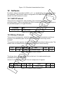
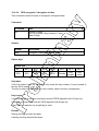
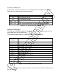
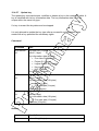
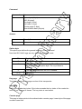
12.2.6 Block Check Character (BCC) The BCC is used to detect transmission errors. The BCC is calculated XOR-ing each byte of the transmission frame excluding the STX/BCC and ETX characters. The flags are part of the data. BCC = ( StatID) XOR ( Length) XOR (Command / Data 0 ) XOR ... XOR (Command / Data N ) 12.2.7 ETX End of transmission. (03h) 12.2.8 Remarks If the reader device receives an invalid instruction frame (i.e. wrong BCC) or the requested station ID does not match the internal ID of the reader, the command is not executed. The reader waits for the next valid frame. The automatic binary time-out (see protocol configuration register) is used to detect incomplete binary frames. 12.2.9 Examples: 02h 64h 01h 78h 1Dh 03h STX Station ID Length ‘x’ BCC ETX This instruction frame will reset the reader module with the station ID 64h. 12.3 Register Set The reader has several system flags used for customization purposes. The flags are stored in its non-volatile EEPROM. The reader accepts changes to these settings only during the start-up phase. Clearing all RFU bits is recommended in order to guarantee compatibility with future releases. The reader can store up to 32 authentication keys internally to login standard Mifare cards. An additional 32 keys can be stored for DESFire authentication. All keys are read only and cannot be accessed via the interface lines. 12.3.1 EEPROM memory organization Register Description 00h … 04h Unique device ID; read only 05h … 09h Administrative data; read only 0Ah Station ID 0Bh Protocol configuration 0Ch Baud rate 0Dh Command Guard Time 0Eh Operation Mode 0Fh Single shot time-out value 10h Internal use / Do not change 11h Internal use / Do not change 12h Internal use / Do not change 13h Protocol configuration 2 14h Reset Off Time 15h Reset Recovery Time 16h Application Family Identifier 17h ISO 14443A Selection Time-out 18h ISO 14443B Selection Time-out 19h SR176 Selection Time-out 1Ah ISO 15693 Selection Time-out 1Bh Protocol configuration 3 1Ch Page Start 1Dh Internal use / Do not change 1Eh Internal use / Do not change 1Fh Page number 20h - 7Fh 80h … EFh RFU User data Figure 12-4: EEPROM memory 12.3.2 Unique device ID (00h – 04h) The unique device ID identifies a reader module. It is factory programmed and cannot be changed. 12.3.3 Station ID (0Ah) The station ID is used in binary mode to address a device in party line set up. The station ID can range from 01h to FEh and can be set freely. The value 00h is reserved for the bus master. All readers send their response to this device. The broadcast message (FFh) forces all readers to response to the command. Default value is 01h. 12.3.4 Protocol configuration (0Bh) The protocol configuration register (PCON) specifies general behavior of the reader device. Default value is 41h. Protocol configuration register Bit 7 Bit 6 Bit 5 Bit 4 Bit 3 Extended ID Extended Protocol Singleshot LED New serial mode Bit 2 Bit 1 Multitag Protocol Bit 0 Autostart Figure 12-5: Protocol configuration register 12.3.4.1 Auto start (default 1) If set, the reader device will start up in continuous read mode automatically. This is only valid in ASCII mode. 12.3.4.2 Protocol (default 0) If Protocol is set to ‘1’, then the reader uses binary protocol mode. Refer to binary protocol for further information on the binary protocol format. Default setting = ASCII protocol (0). 12.3.4.3 Multitag (default 0) The Multitag flag will enable multi-tag recognition in continuous read mode. All tags are detected and displayed. Due to the more complex search algorithm, the continuous read command decreases its detection speed. 12.3.4.4 New Serial Mode (default 0) If New Serial Mode is set to ‘1’, new serial mode is enabled. The leading character ‘M’ is added to the serial number of ISO 14443 type A tags, a leading 'Z' character is added to ISO 14443 type B tags and a leading 'S' character for SR176 tags. 12.3.4.5 LED (default 0) If set the reader suppresses any LED activity. The user manages the state of the LEDs. 12.3.4.6 Single Shot (default 0) If Single Shot is set, the reader displays the serial number of a tag in continuous read mode once within a specified time-out. The time-out is defined at EEPROM register 0Fh. The delay time can be adjusted stepwise in 100ms steps. 00h indicates no delay and FFh indicates infinite delay. 12.3.4.7 Extended Protocol (default 1) If Extended Protocol is set, the transfer data telegram command supports ISO144434 and automatically process the WTX and chaining for smaller frames. If sending ISO 14443-3 commands this flag has to be switched off. The transfer data telegram command is only supported in normal mode, not in transmit / receive mode. 12.3.4.8 Extend ID (default 0) If Extended ID is set, the reader extends the serial number of tags with additional bytes. ISO 14443 A tags (5/8/11 bytes transmitted) Tag type Serial number 1 byte 4 / 7 / 10 bytes Figure 12-6: ISO 14443 A Extended Serial number The tag type byte indicates the type of cascade level. Tag type Description 00h Cascade level 1 transponder 01h Cascade level 2 transponder 02h Cascade level 3 transponder Figure 12-7: ISO 14443 A tag type ISO 14443 B tags (12 bytes transmitted) Serial number Application data Protocol info CID 4 bytes 4 bytes 3 bytes 1 byte Figure 12-8: ISO 14443 B Extended Serial number For detailed description of Application Data, Protocol Info and CID, refer to the ISO 14443 documentation [1]. 12.3.5 BAUD, Baud rate control register (0Ch) The baud rate register defines the communication speed of the reader device. Default value is 00h. Baud rate register Bit 7 Bit 6 Bit 5 Bit 4 Bit 3 Bit 2 Bit 1 Bit 0 RFU RFU RFU RFU RFU BS2 BS1 BS0 Figure 12-9: Baud rate register This register defines the baud rate of the device. BS2 BS1 BS0 Baud rate 0 0 0 9600 baud (default) 0 0 1 19200 baud 0 1 0 38400 baud 0 1 1 57600 baud 1 0 0 115200 baud 1 0 1 230400 baud (depends on the used interface chip) 1 1 0 460800 baud (depends on the used interface chip) Figure 12-10: Baud rate settings With the high baud rates (230400 and 460800 baud), proper operation depends on the interface chip used. Please note that some of the interface chips available do not support these high baud rates. The following table describes the exact baud rates used by the reader. Baud rate Exact baud rate Difference 9600 baud 9603 baud 0.03 % 19200 baud 19207 baud 0.04 % 38400 baud 38305 baud -0.25 % 57600 baud 57458 baud -0.25 % 115200 baud 114915 baud -0.25 % 230400 baud 233793 baud 1.47 % 460800 baud 452000 baud -1.91 % Figure 12-11: Exact baud rates The following table describes the communication settings Description 8 data bits No parity bit 1 stop bit No flow control Figure 12-12: Communication settings 12.3.5.1 CF Card Version The Baud rate of the CF Card version is limited to 115200 baud. 230400 and 460800 are not supported. 12.3.6 Command Guard Time (0Dh) The Command Guard Time is used to ensure that commands are not sent to fast consecutively. Following commands are sent after the guard time is elapsed. One time slice is around 37,8us. The longest timeout value is 9,6ms (FFh). The default value is 20h (1,2ms). 12.3.7 OPMODE, operating mode register (0Eh) The operation mode register defines which tag types the reader supports. This register enables fast tag recognition because only defined tag types are requested. ICODE Bit 2 Bit 1 Bit 0 (LSB) ISO 14443A Bit 3 SR176 Bit 4 ISO 15693 Bit 5 ICODE EPC Bit 6 ICODE UID RFU Bit 7 (MSB) ISO 14443B Operation mode register Figure 12-13: Operation mode register 12.3.8 Single Shot Time-out (0Fh) The time-out value defines the delay time between two responses of the reader. It only has effect in continuous read mode. To enable the time-out, the single shot flag has to be set. See the protocol configuration register above. One time-out slice is around 100ms. Exact timing depends on the protocol used. Value 00h indicates no delay time. Default value is 0Ah (1 second). 12.3.9 Protocol configuration 2 (13h) The protocol configuration register 2 (PCON2) further specifies the general behavior of the reader device. Default value is 00h. Protocol configuration 2 register Bit 7 Bit 6 Bit 5 Bit 4 Disable Enable ISO Reset ISO 14443 -4 14443B Recovery Time AntiMultiplier Error Handling collision Bit 3 Bit 2 Bit 1 Bit 0 Noisy Environment Enable binary frame v2 Disable start-up message Disable multitag reset Figure 12-14: Protocol configuration register 12.3.9.1 Disable multi-tag reset (default 0) If set, the reader does not reset before the multi-tag list and multi-select command have been performed. 12.3.9.2 Disable start-up message (default 0) If Disable start-up message is set, the reader suppresses the start-up message in ASCII mode. This flag is ignored in binary protocol mode. 12.3.9.3 Enable binary frame v2 (default 0) If Enable binary frame v2 is set, the reader sends version 2 binary frames. The get station ID command always sends version 1 binary frames! 12.3.9.4 Noisy Environment (default 0) If Noisy Environment is set, the continuous read mode can only be aborted with the '.' character. When working in a noisy environment, the probability for a reception of an arbitrary/stochastic signal is quite high. This implies a high probability of an unintentional command execution. To reduce this probability, only one character (out of 255) is chosen (‘.’) to be interpreted as the continuous read stop command. 12.3.9.5 Reset Recovery Time Multiplier (default 0) Multiplies the Reset Recovery Time, including the recovery time of the field reset command. Reset Recovery Time Multiplier Reset Recovery Time 0 1x 1 2x 2 3x 3 4x Figure 12-15: Reset Recovery Time Multiplier 12.3.9.6 Enable ISO14443 B Anti-collision (default 0) If set, the anti-collision algorithm for ISO 14443 B tags is enabled. 12.3.9.7 Disable ISO 14443-4 Error Handling (default 0) If Disable ISO 14443-4 Error Handling is set, ISO14443-4 Error Handling is disabled. The error handling always uses the TMR time-out. 12.3.10 Reset Off Time (14h) The Reset Off Time register represents the field off time in ms. This register is used for the select, continuous read and multi-tag commands. Default value is 0Ah. 12.3.11 Reset Recovery Time (15h) The Reset Recovery Time register represents the recovery time in ms after the field is turned on. This register is used for the select, continuous read and multi-tag commands. Default value is 25h. 12.3.12 Application Family Identifier (16h) The AFI (Application Family Identifier) is only supported for ISO14443B and ISO15693 tags. If the set value is different from 00h, the AFI is used. Only transponders with an identical AFI will answer to the reader. Default value is 00h. 12.3.13 Selection Time-out ISO 14443A (17h) The Selection Time-out represents the reader card communication time-out for the select, high speed select, continuous read, multilist, multiselect and Mifare® login command with ISO 14443A tags. Use low values for a better reaction time between the card and the reader. One time slice is around 300us. The default value is 10h. 12.3.14 Selection Time-out ISO 14443B (18h) The Selection Time-out represents the reader card communication time-out for the select, high speed select, continuous read, multilist and multiselect commands with ISO 14443B tags. For a better reaction time, use low values. One time slice is around 300µs. The default value is 50h. 12.3.15 Selection Time-out SR176 (19h) The Selection Time-out represents the reader card communication time-out for the select, continuous read, multilist and multiselect command with SR176 tags. For a better reaction time, use low values. One time slice is around 300µs. The default value is 10h. 12.3.16 Selection Time-out ISO 15693 (1Ah) The Selection Time-out represents the reader card communication time-out for the select, high speed select, continuous read, multilist, multiselect and Mifare® login command with ISO 15693 tags. Use low values for a better reaction time between the card and the reader. One time slice is around 300us. The default value is 20h. 12.3.17 Protocol configuration 3 (1Bh) The protocol configuration register 3 (PCON3) further specifies the general behavior of the reader device. Default value is 00h. Protocol configuration 3 register Bit 7 Bit 6 Bit 5 RFU ReqA Extended ID Bit 4 Bit 3 Internal use / do not change Bit 2 Page Read Bit 1 Bit 0 RFU Disable automatic ISO 14443-4 timeouts Figure 12-16: Protocol configuration register 12.3.17.1 Disable automatic ISO 14443-4 timeouts (default 0) If Disable automatic ISO 14443-4 timeouts is set the automatic ISO 14443-4 timeouts are disabled. The timeouts specified with TMR registers are used. 12.3.17.2 Page read (default 0) If set the continuous read mode retrieves the content of the tag instead of the serial number. The register Page Start (1Ch) defines the start block and the Page Number (1Fh) defines the number of blocks to be read. 12.3.17.3 ReqA Extended ID (default 0) If set the Extended ID information for ISO14443 A tags replaces the cascade level information (1 byte) with Request A answer (2 bytes). 12.3.18 User data (80h - EFh) These registers are for free use. 12.4 Instruction Set Following table describes all the commands of the reader device. Each command returns an answer to the host. Exceptions are mentioned explicitly. The green LED acknowledges a successfully executed command. The red LED indicates an error. 12.4.1 Common Commands Overview Command Description '!' Test continuous read / Check KTT upload status 'c' Continuous read '.' Abort continuous read, refer to continuous read 'dg' / 'dn' / 'dr' Set LED 'ds' DES encryption / decryption of data 'f' DESFire command set 'g' Get ID 'h' High speed select 'k' Lock block 'm' MultiTag select / tag list 'o+a' / 'o+b' / 'o+d' / 'o+e' / 'o+i' / 'o+s' / 'o+v' Include tag type 'o-a' / 'o-b' / 'o-d' / 'o-e' / 'o-i' / 'o-s' / 'o-v' Exclude tag type 'oa' / 'ob' / 'od' / 'oe' / Set tag type 'oi' / 'ot' / 'os' / 'ov' 'of' Set configuration flags 'og' Set configuration register 'poff' / 'pon' Antenna power off/on 'pr' / 'pw' Read / write user port 'q' Quiet 'ra' Resend last answer 'rp' Read EEPROM register 'r' / 'rb' Read block 's' Select 'v' Get version 'w' / 'wb' Write block 'wp' Write EEPROM register Figure 12-17: Command overview (Part 1) Command Description 'x' Reset 'y' Field reset ISO 14443 Type A (Mifare) only commands '+' Increment value block (credit) '-' Decrement value block (debit) '=' Copy value block (backup) 'l' Login (authenticate tag) 'rv' Read value block 'wv' Write value block Key Management 'ar' Authenticate to reader 'ia' Get key access rights 'it' Get key status 'rt' Reset key table 'ua' Update key access rights 'uc' Change key type 'uk' Update key my-d Secure commands '!' Check KTT upload status / Test continuous read '*' Abort KTT upload 'as' Authenticate to sector 'ik' Issue transponder key 'ut' Prepare for KTT 'z' my-d command Figure 12-18: Command overview (Part 2) 12.4.2 Error Codes Following figure shows an overview of all error messages of the reader device. Error Code Description ‘?’ Unknown command 'C' Collision or CRC/MAC Error ‘F’ General failure ‘I’ Invalid value format, specified block does not match the value format ‘N’ No tag in the field 'O' Operation mode failure or file not selected ‘R’ Command parameter out of range 'X' Authentication failed Figure 12-19: Error codes 12.4.3 Common commands 12.4.3.1 Test Continuous Read / Check KTT Upload Status This command tests the state of the continuous read command and the state of the Prepare for KTT 'ut' command. The test continuous read command is only valid in ASCII mode. Command Command Data '!' None Answer Answer Description '!' Continuous read mode is active. 00h Keys from KTT successfully uploaded 01h Error during key upload detected, upload aborted 02h No KTT found, other tag was detected FFh Prepare for KTT is in awareness mode 'F' Continuous read and Prepare for KTT is not active. no response Key uploading is in progress 12.4.3.2 Continuous Read The reader device reads and displays serial numbers continuously while one or more tags remain in the field. This command stops if any character is sent to the reader module. The reader module returns the character ‘S’ (53h). The reader supports different tag types at the same time. To increase the reading performance switch to a single tag mode. If more than one tag of the same type should be detected at the same time, the Multitag flag must be activated. The response data length depends on the tag type. Command Command Data 'c' None Answer Answer Description Data Serial number (n bytes) 'N' Error: No Tag in the field (only binary protocol) 12.4.3.2.1 Multitag continuous read mode If the Multitag flag is set in the Protocol Configuration (PCON) register the reader reads multiple tags continuously. 12.4.3.2.2 Auto start The continuous read mode is started automatically in ASCII mode. The auto start flag must be set in the PCON register. 12.4.3.2.3 Noisy Environment If the Noisy Environment flag is set, the continuous read mode can only be aborted with the '.' character. This is only valid in ASCII mode. 12.4.3.2.4 Binary mode This command is fully supported in binary protocol mode except the test continuous read command and the noisy environment flag. Do not use this command on bus system environment in binary mode, because the continuous read mode will take possession of the bus system. 12.4.3.2.5 Simple access control applications Serial numbers are always sent plain. Data encryption is activated after a successful login. For simple access control applications the use read-only blocks for the identification of the tag is recommended. Reading any block (even the manufacturer block) of the transponder will increase your security. 12.4.3.3 Set LED This command controls the LED activity. If the LED flag is set, the automatic LED function is switched off. The user can set the state of the LED manually. Command Command Data 'dg' None 'dr' None 'dn' None Answer Answer Description 'DG' 'DR' 'DN' String of LED state Example Command Answer Description 'dg' DG Switch on LED green, LED red off 'dr' DR Switch on LED red, LED green off 'dn' DN Switch off both LEDs 12.4.3.4 DES encryption / decryption of data This command returns 8 bytes of encrypted / decrypted data. Command Command Data 'ds' Options (1 byte) Key (8/16 bytes) / Key Number (1 byte) Data (8 byte) Answer Answer Description Data Encrypted / Decrypted data (8 bytes) Option byte Option byte Bit 7 Bit 6 Bit 5 Bit 4 Bit 3 Bit 2 Bit 1 Bit 0 RFU RFU RFU RFU RFU Encode Key Length Key Index Key Index If the Key Index is set, the command only needs the key number (1 byte) instead of the key (8/16 bytes). The key number corresponds to the key number used in the key management. Key Length If the Key Length is set, the command uses the TDES algorithm with 16-byte key. If cleared, the command uses the DES algorithm with 8-byte key. If key index is used the key length flag is valid. Encode Setting this flag encodes the data. Clearing this flag decodes the data. 12.4.3.5 Get ID This command returns the station ID of the reader device. The answer is time slotted to enable the detection of all devices in party line mode. The station ID has only effect in binary mode. Command Command Data 'g' None Answer Answer Description Data Station ID of the reader device (1 byte) 12.4.3.5.1 Time slotted answer In party line mode, more than one reader can be used simultaneously. The time slotted answer allows separating in time the answers from all connected devices. The station ID is used to determine the correct time slot. The reader supports up to 254 unique time slots. The following formula calculates the duration of one time slot (only one baud rate is supported per party line): T0 [ s ] = 10 *6 Baudrate Figure 12-20: Time slot formula The following figure shows the timing diagram of time slotted answers. Timeslot 0 1 2 3 4 5 T0 T1 T2 T3 T4 T5 … 252 253 254 T252 T253 T254 'g' → HOST ← 01 Reader (01) ← 03 Reader (03) ← 04 Reader (04) Reader (254) Figure 12-21: Timing diagram of time slotted answers ← 254 12.4.3.5.2 Binary Protocol Version 2 This command never sends version 2 binary frames. 12.4.3.6 High speed select This command selects a card in the antenna field (according to the selection criteria) or prepares a multiselect command, switches to high baud rates and enables 256byte frames. If execution is successful, the command returns the UID of the selected card and the used baud rate. The reader automatically detects the maximum frame size of the card. The reader also tries to communicate to the transponder with the specified baud rate. If no communication is possible, the reader will automatically decrease the speed to the next lower value. This command can also force the reader to the communication speed and frame size of the tag to the specified values. This is only needed if the high speed select is done manually with the transfer command. Command Command Data ‘h’ Option byte (1 byte) 00h … select a single card with 106kBaud 02h … select a single card with 212kBaud 04h … select a single card with 424kBaud 08h … select a single card with 848kBaud 10h … prepare next multiselect for 106kbaud 12h … prepare next multiselect for 212kbaud 14h … prepare next multiselect for 424kbaud 18h … prepare next multiselect for 848kbaud 20h … forces reader to 106kBaud 22h … forces reader to 212kBaud 24h … forces reader to 424kBaud 28h … forces reader to 848kBaud 30h – 38h … force tag frame size Answer Answer Description Data (n bytes) Serial number + frame size used and baud rate + frame size and baud rate (1byte) 'F' Error: General failure ‘N’ Error: No Tag in the field Examples High speed select Command Description h08 1234567890ABCD84 Select the card with UID 1234567890SABCD. The card supports a 256-byte frame size and 424kBaud on the air interface. High speed multiselect Command Description h18 m1234567890ABCD<CR> Prepare next multiselect for 848kBd 1234567890ABCD84 Select the card with UID 1234567890SABCD. The card supports a 256-byte frame size and 424kBaud on the air interface. 12.4.3.6.1 Answer from 0xh and 1xh The lower nibble contains the baud rate used for the air interface. Baud Rate Description x0 106kBaud x2 212kBaud x4 424kBaud x8 848kBaud Figure 12-22: Baud Rate values The higher nibble contains the frame size used for the air interface. Frame Size Description 0x 16 Bytes 1x 24 Bytes 2x 32 Bytes 3x 40 Bytes 4x 48 Bytes 5x 64 Bytes 6x 96 Bytes 7x 128 Bytes 8x 256 Bytes Figure 12-23: Frame Size 12.4.3.6.2 Answer from 2xh and 3xh The option byte is returned as the answer. 12.4.3.6.3 Select a single tag No previous continuous read is required. The command executes an automatic field reset. 12.4.3.6.4 Extended ID See above for more information on Extended ID. The RATS answer is inserted between the serial number and baud rate / frame size byte for ISO14443 A tags. 12.4.3.6.5 Multiple tags This command with parameter 1xh prepares the next multiselect command as a highspeed select. Any other command will disable the preparation. 12.4.3.6.6 RATS Guard Time SFGT A high-speed select with parameters 0xh and 1xh automatically waits the SFGT guard time received from the tag before sending the PPS command. 12.4.3.7 Lock block This command locks a block permanently. Only SR176 and ISO 15693 tags are supported. Command Command Data 'k' Block address (1 byte) Answer Answer Description data 'K' + page address 'F' Error: Lock failure 'N' Error: No tag in field 'O' Error: Operation mode failure (only SR176 and ISO 15693 tags are supported) 'X' Error: Block already locked Example Command Description k05 K05 Lock block 05. 12.4.3.7.1 Operation mode failure 'O' The presented tag is not a SR176 or a ISO 15693 tag. 12.4.3.7.2 Apply settings After locking a block permanently, the tag needs to be selected for the settings to apply. 12.4.3.8 Multi-Tag Selection / List This command detects several tags at the same time. It replaces the fast select command ('s') in multiple tag surroundings. The Multi-Tag List command lists all tags with their serial numbers. Use the Multi-Tag Select command to select a single tag. Each tag has to be selected separately. Command Command Data 'm' Serial number (n bytes) <CR> (1 byte) Answer Answer Description Data serial number 'N' Error: No Tag in the field Example Command Description m<CR> 04E9E700000000 first card 34030F07 second card 02 number of detected tags m04E9E700000000<CR> Select card with its serial number 12.4.3.8.1 Multi-tag list Sending a <CR> as the first parameter, the reader returns a list of all tags present in the antenna field. In the end the total number of tags detected is returned. 12.4.3.8.2 Reading distance Each card needs a specific amount of power. The reader always provides the same power level. Therefore, the reading distance will decrease if more tags are present. Basically, the reading distance depends on the tag, the antenna and the tuning of the antenna. 12.4.3.8.3 Multi-tag select Using the serial number with <CR> as parameter, the corresponding tag will be selected. High-level interactions can be performed addressing only this card. All other tags remain silent. 12.4.3.8.4 Multi-tag reset The antenna field reset can be deactivated with the Protocol configuration 2 register. By suppressing the antenna field reset, it is possible to detect only new tags in the antenna field. 12.4.3.8.5 Maximum number of tags The maximum number of tags in the antenna field is limited to 64 and by the physical characteristics of the antenna. 12.4.3.9 Include tag type This command includes a specific tag type to those addressed by the reader device. Command Command Data ‘o+’ Tag type (1 byte) Answer Answer Description 'O+' + tag type (1 byte) Command code + String of tag type Tag type character Refer to Set tag type. Example Command Description o+a Include ISO14443-A to the tag types addressed by the reader device. 12.4.3.10 Exclude tag type This command excludes a specific tag type from being addressed by the reader device. Command Command Data ‘o-’ Tag type (1 byte) Answer Answer Description 'O-' + tag type (1 byte) Command code + String of tag type Tag type character Refer to Set tag type. Example Command Description o-a Exclude ISO14443-A from the tag types addressed by the reader device. 12.4.3.11 Set tag type This command sets up the reader for a specific tag type. The continuous read function will speed up because only this type of tag is addressed. After a reset, the reader starts as defined in its start-up configuration. Command Command Data 'o' ISO type (1 byte) 'a' … ISO 14443 Type A 'b' … ISO 14443 Type B 'd' … ICODE UID 'e' … ICODE EPC 'i' … ICODE 's' … SR176 't' … activate all tags 'v' ... ISO 15693 Answer Answer Description 'OA' 'OB' 'OD' 'OE' 'OI' 'OS' 'OT' 'OV' String of tag type Example Command Description oa Sets the reader device to address ISO14443-A type tags. 12.4.3.12 Set Configuration Flags This command allows setting some configuration flags just in time; no reset is needed. The values are not stored in the EEPROM; therefore the changed values are not available after a reset. Command Command Data of flag type (1 byte) data (1 byte) Answer Answer Description Data (1 byte) Current state of changed flag. 'R' Error: Out of range Example Command Description of0101 Answer: 01 Enables the New Serial Mode flag. Flag Types The following table shows the Flag Type with its corresponding flag from the specified Protocol Configuration Register. Flag Type Corresponding Flag Protocol Configuration Register Valid values 00h Multitag 1 00 / 01 01h New Serial Mode 1 00 / 01 02h LED 1 00 / 01 03h Single Shot 1 00 / 01 04h Extended Protocol 1 00 / 01 05h Extended ID 1 00 / 01 06h Disable Multitag Reset 2 00 / 01 07h Noisy Environment 2 00 / 01 08h Reset Recovery Time Multiplier 2 00 … 03 09h Enable ISO14443 B Anticollision 2 00 / 01 0Ah Disable ISO14443-4 Error Handling 2 00 / 01 0Bh Disable automatic ISO14443-4 timeouts 3 00 / 01 0Dh Page Read 3 00 / 01 11h ReqA Extended ID 3 00 / 01 Figure 12-24: Flag Type with corresponding flag 12.4.3.12.1 Out of range failure 'R' The entered flag type is out of range. 12.4.3.13 Set Configuration Register This command allows setting some configuration registers just in time; no reset is needed. The values are not stored in the EEPROM; therefore the changed values are not available after a reset. Command Command Data og Register type (1 byte) data (1 byte) Answer Answer Description Data (1 byte) Current state of changed register. 'R' Error: Out of range Example Command Description og0450 Answer: 50 Sets the Reset Recovery Time to 50h. Register Types The following table shows the Register Type with its corresponding register. Register Type Corresponding Register 00h Single shot time-out value 01h Internal use / Do not change 02h Internal use / Do not change 03h Reset Off Time 04h Reset Recovery Time 05h ISO 14443A Selection Time-out 06h ISO 14443B Selection Time-out 07h SR176 Selection Time-out 08h AFI 0Ch Page Read Start 0Dh Page Read Number 0Eh Command Guard Time Figure 12-25: Register Type with corresponding register 12.4.3.13.1 Out of range failure 'R' The entered register type is out of range. 12.4.3.14 Antenna power on/off This command controls the antenna power. It can be used to decrease the power consumption of the reader. Command Command Data 'pon' Switch reader on 'poff' Put reader in standby mode Answer Answer Description 'P' Positive acknowledge Example Command Description poff Put reader in standby mode 12.4.3.14.1 Power off The reader enters standby mode. Power consumption is decreased. All tags in the antenna field are powered off and reset. Standby mode is only entered manually. To switch off the whole unit, pin 16 (Enable) has to be set to logic low. 12.4.3.14.2 Power on The reader leaves standby mode and is ready for the next command. Sending a tag command (i.e. select, continuous read) the reader is powered up. 12.4.3.15 Read/Write user port This command sets or reads the state of the user port (pin 14) of the OEM reader device. The port is set either as output or as input. Command Command Data 'pr' None 'pw' State of user port (1 Byte) Answer Answer Description Data State of user port (1 Byte) 'C' Error: Error correction fails 'F' Error: Transmission Error / No answer received Example Command Description pr Reads user port pw01 Sets user port state to high 12.4.3.15.1 Read port The port read command returns the current state of the USER port. Port state Description 00h USER port is low 01h USER port is high Figure 12-26: Read USER port return values 12.4.3.15.2 Write port If user port is used as an output, a 1kΩ resistor has to be integrated into the wire. Otherwise the reader device can be damaged. Port state Description 00h Sets USER port to low 01h Sets USER port to high 02h – 7Fh RFU 80h - FFh Sends a serial data frame and checks the received frame Figure 12-27: Write User port settings Sending a Data Frame If the highest bit (MSB) is set in the State of the User Port, the command sends a serial data frame out the USER port. The frame includes a start bit, 8 data bits, parity bit and a stop bit. Transmit Frame Description Low Start bit Low RFU Data Bit 6 State of the User Port Bit 6 Data Bit 5 State of the User Port Bit 5 Data Bit 4 State of the User Port Bit 4 Data Bit 3 State of the User Port Bit 3 Data Bit 2 State of the User Port Bit 2 Data Bit 1 State of the User Port Bit 1 Data Bit 0 State of the User Port Bit 0 Parity Bit Even Parity Bit High Stop Bit Figure 12-28: Sending Serial Data Frame After 2ms Guard Time the answer should be received on the User Port otherwise an error is returned. Receive Frame Low Error Bit Description Start bit If set, an error was detected. Data Bit 6 State of the User Port Bit 6 Data Bit 5 State of the User Port Bit 5 Data Bit 4 State of the User Port Bit 4 Data Bit 3 State of the User Port Bit 3 Data Bit 2 State of the User Port Bit 2 Data Bit 1 State of the User Port Bit 1 Data Bit 0 State of the User Port Bit 0 Parity Bit Even Parity Bit High Stop Bit Figure 12-29: Receiving Serial Data Frame If the Error bit is set or the Parity Bit is not correct, the Write User Port command returns an error code. 12.4.3.16 Quiet This command sets a selected tag into halt state. Only ISO14443 A+B and SR176 tags are supported. Command Command Data 'q' None Answer Answer Description 'Q' Halt state successfully set. 'N' Error: No Tag in the field 12.4.3.16.1 ISO 14443 Type A With ISO14443 Type A tags, the Quiet command always answers with 'Q' because the halt command does not send any acknowledge. 12.4.3.16.2 ISO 14443 Type B Some ISO14443 Type B tags do not support this command or do not respond. ‘Quiet’ is an ISO 14443-4 command, so it will work only if the ‘Deselect’ command is supported by the corresponding transponder. 12.4.3.16.3 SR176 With SR176 tags the Quiet command always answer with 'Q' because the completion command does not send any acknowledge. 12.4.3.17 Resend Last Answer This command resends the last answer from the internal serial buffer of the reader. Command Command Data 'ra' Resend last answer 12.4.3.18 Read block This command reads a data block on a card. The size of the returned data depends on the tag used. The block address range depends on the tag as well. Command Command Data 'r' Block address (1 byte), valid range 00h – 40h 'rb' Block address (1 byte) Answer Answer Description Data data block (depends on tag type) 'F' Error: read failure 'N' Error: No tag in field 'O' Error: Operation mode failure 'R' Error: Out of range Example Command Description rb05 Reads block 05. 12.4.3.18.1 Read failure 'F' This error is returned if either the reader receives bad data or the block address exceeds the block address range of the sector. 12.4.3.18.2 No tag in field 'N' The tag does not respond. There is either no tag present or addressed. 12.4.3.18.3 Operation mode failure 'O' The presented tag is not ISO14443 type A, SR 176, ICode, ICode-UID and ISO 15693 compliant. For ISO 14443 type A only Mifare tags are supported. 12.4.3.18.4 Out of range failure 'R' The block address of the 'r' command is higher than 40h. The block address of the 'r' command conflicts with other commands, therefore the block address has to be limited to 40h. Use the 'rb' command instead. 12.4.3.19 Read reader EEPROM This command reads the internal reader EEPROM. It contains all start-up parameters and the device ID. Changes in the start-up settings will only go into effect after a reset of the device. Command Command Data 'rp' EEPROM address (1 byte) 00h … EFh Answer Answer Description Data EEPROM data (1 byte) 'R' Error: Out of range failure Example Command Description rp0B Reads protocol configuration register. 12.4.3.19.1 Out of range failure 'R' The entered EEPROM address is not valid. 12.4.3.20 Select This command selects a single card in the antenna field. It can only be used in single tag mode. If successfully executed, the command returns the UID of the selected card. The reader detects the length of the UID automatically. Command Command Data 's' None Answer Answer Description Data serial number 'N' Error: No Tag in the field Example Command Description s 1234567890ABCD Select the card with UID 1234567890SABCD. 12.4.3.20.1 Select a single tag No previous continuous read is required. The command executes an automatic field reset. 12.4.3.20.2 Extended ID See above for more information on Extended ID. 12.4.3.20.3 Multiple tags This command is designed for fast access of a single tag in the field. If multiple cards are used the 'm' instruction has to be used instead. 12.4.3.21 Get Version This command returns the current version of the reader module. Command Command Data 'v' None Answer Answer Description 'MultiISO 1.0' + <CR> + <LF> ASCII Mode 02 00 0C 4D 75 6C 74 69 49 53 4F 20 31 Binary Mode 2E 30 1F 03 Example Command Description v ‘MultiISO 1.0’ Version of the reader module 12.4.3.22 Write block This command writes data to a block. A read is done automatically after every write to ensure correct writing. Command Command Data 'w' Block address (1 byte), valid range 00h – 40h Data (n bytes) 'wb' Block address (1 byte) Data (n bytes) Answer Answer Description Data Data block (depends on tag type) 'F' Error: Write failure 'N' Error: No tag in field 'O' Error: Operation mode failure 'R' Error: Out of range Example Command Description wb0511223344 Writes data 11223344 on block 05. 12.4.3.22.1 Write failure 'F' This error is displayed if bad transmission conditions are given. If the block address exceeds the physical number of blocks of a tag, this error is shown. 12.4.3.22.2 No tag error 'N' This error is returned if no tag is present or the card does not respond. 12.4.3.22.3 Operation mode failure 'O' The presented tag is not ISO14443 type A, SR 176, ICode, ICode-UID and ISO 15693 compliant. For ISO 14443 type A only Mifare tags are supported. 12.4.3.22.4 Out of range failure 'R' The block address of the 'w' command is higher than 40h. The block address of the 'w' command conflicts with other commands, therefore the block address has to be limited to 40h. Use the 'wb' command instead. 12.4.3.23 Write EEPROM Writes to the internal reader EEPROM. It contains all start-up parameters and the device ID. Changes to the start-up settings will only go into effect after a reset of the device. Command Command Data 'wp' Address (1 byte), valid range 0Ah - EFh Data (1 byte) Answer Answer Description Data EEPROM data (1 byte) 'F' Error: Read after write failure 'R' Error: Out of range failure Example Command Description wp0A01 Set EEPROM address 0A (Station ID) to 01h 12.4.3.23.1 Out of range failure 'R' The entered address exceeds the address range. 12.4.3.24 Reset This command executes a power on (software) reset. New configuration settings will be loaded. It resets all tags in the antenna field. Command Command Data 'x' None Answer Answer Description MultiISO 1.0' + <CR> + <LF> ASCII Mode None Binary Mode 12.4.3.24.1 Disable Start-up Message If the start-up message is disabled in the protocol configuration register 2, the ASCII mode does not respond with the version of the reader. 12.4.3.24.2 Reset Timing The power up timing depends on environmental conditions such as voltage ramp up. For handheld devices the timing can vary based on the charge state of the battery. 12.4.3.25 Field Reset The field reset switches off the antenna field for the specified duration. All tags need a certain amount of time to initialize before a command can be processed. The second byte specifies the field recovery time. Command Command Data 'y' Off time in milliseconds (1 byte) Field recovery time in milliseconds (1 byte) Answer Answer Description 'Y' After the field reset the reader sends back a ‘Y’ to acknowledge the command. 12.4.4 ISO 14443 Type A (Mifare) only commands 12.4.4.1 Increment value block (credit) Increments a value block with a defined value. A read is done automatically after a write to verify data integrity. The command fails if the source block is not in value block format. A previous login is needed to access a block. Command Command Data '+' Block (1 byte) Value (4 bytes) Answer Answer Description Data Value (4 bytes) 'I' Error: value block failure 'F' Error: increment failure 'N' Error: No tag in field 'O' Error: Operation mode failure Example Command Description +0400000001 Adds 1 to value block 4 +0500000100 Adds 256 to value block 5 12.4.4.1.1 No value block 'I' Specified block does not match the value format. The value block is corrupted. A backup block can be used to restore the correct value. 12.4.4.1.2 Increment failure 'F' This indicates a general failure during the increment procedure or an inability to read after the write process. 12.4.4.1.3 No tag error 'N' The reader does not detect a response from the tag. There is either no tag present or the tag does not respond to the request. 12.4.4.1.4 Operation mode failure 'O' The tag is not ISO14443 type A compliant. 12.4.4.2 Decrement value block (debit) Decrements a value block with a defined value. A read is done automatically after the write to verify data integrity. The command fails if the source block is not in value block format. A previous login is needed to access a block. Command Command Data '-' Block (1 byte) Value (4 bytes) Answer Answer Description Data Value (4 bytes) 'I' Error: value block failure 'F' Error: decrement failure 'N' Error: No tag in field 'O' Error: Operation mode failure Example Command Description -0400000001 Subtract 1 to value block 4 -0500000100 Subtract 256 to value block 5 12.4.4.2.1 No value block 'I' Specified block does not match the value format. The value block is corrupted. A backup block can be used to restore the correct value. 12.4.4.2.2 Decrement failure 'F' This indicates a general failure during the decrement procedure or an inability to read after the write process. 12.4.4.2.3 No tag error 'N' The reader does not detect a response from the tag. There is either no tag present or the tag does not respond to the request. 12.4.4.2.4 Operation mode failure 'O' The tag is not ISO14443 type A compliant. 12.4.4.3 Copy value block (backup) Copies a value block to another block of the same sector. A read is done automatically after the write to ensure data integrity. Used for backup and error recovery. A previous login is needed to access a block. Command Command Data '=' Source block (1 byte) Target block (1 byte) Answer Answer Description Data New value of target block (4 bytes). 'I' Error: value block failure 'F' Error: copy failure 'N' Error: No tag in field 'O' Error: Operation mode failure Example Command Description =0405 Copy value block 4 to block 5 =0506 Copy value block 5 to block 6 12.4.4.3.1 Target block The target block does not need to be a valid value block. If the source block is not in value format, the command fails. 12.4.4.3.2 No value block 'I' Source value block is not in a valid value block. The value block is corrupted. A backup block can be used to restore the correct value. 12.4.4.3.3 Copy failure 'F' This indicates a general failure during the copy procedure or an inability to read after the write process. 12.4.4.3.4 No tag error 'N' The reader does not detect a response of the tag. There is either no tag present or the tag does not respond to the request. 12.4.4.3.5 Operation mode failure 'O' The tag is not ISO14443 type A compliant. 12.4.4.4 Login (authenticate tag) Performs an authentication in order to access one sector of a Mifare® card. Only one sector can be accessed at a time. Command Command Data 'l' Sector (1 byte), valid range 00h - 3Fh Key type (1 byte) AAh authenticate with key type A FFh authenticate with key type A, transport key FFFFFFFFFFFFh BBh authenticate with key type B 10h … 2Fh authenticate with key type A using stored key (00h … 1Fh) 30h … 4Fh authenticate with key type B using stored key (00h … 1Fh) Key (6 bytes) / <CR> (1 byte), optional By transmitting <CR> instead of the keydata authentication is done with manufacturer’s transport keys (A0A1A2A3A4A5h, B0B1B2B3B4B5h, FFFFFFFFFFFFh). Answer Answer Description data Login status (1 byte) 'L' Login success 'F' Error: General failure 'N' Error: No tag 'O' Error: Operation mode failure 'R' Error: Out of range 'X' Error: Authentication failed Example Command Description l02AA<CR> Authenticate for sector 2, using the transport key A (A0A1A2A3A4A5h, key type A) l3FBB<CR> Authenticate for sector 63, using the transport key 2 (B0B1B2B3B4B5h, key type B) l04FF<CR> Authenticate for sector 4, using the transport key 3 (FFFFFFFFFFFFh, key type A) l0FAAFFFFFFFFFFFF Authenticate for sector 15, using key FFFFFFFFFFFFh, key type A l0E14 Authenticate for sector 14, using EEPROM key 4, key type A l0530 Authenticate for sector 5, using EEPROM key 0, key type B l0732 Authenticate for sector 7, using EEPROM key 2, key type B l0110 Authenticate for sector 1, using EEPROM key 0, key type A l0ABBFF12FFFFFF35 Authenticate for sector 10, using key FF12FFFFFF35h, key type B 12.4.4.4.1 No tag error 'N' The reader does not detect a response from the tag. There is either no tag present or the tag does not respond to the request. 12.4.4.4.2 Operation mode failure 'O' The tag is not ISO14443 type A compliant. 12.4.4.4.3 Out of range failure 'R' The entered key type or the sector is out of range. 12.4.4.4.4 <CR> Three transport keys are implemented to access cards quickly. By transmitting <CR> instead of the key, the reader module uses the transport keys for the login procedure. Command Description LxxAA<CR> Authenticate for sector xx, using the transport key 1 (A0A1A2A3A4A5h, key type A) LxxBB<CR> Authenticate for sector xx, using the transport key 2 (B0B1B2B3B4B5h, key type B) LxxFF<CR> Authenticate for sector xx, using the transport key 3 (FFFFFFFFFFFFh, key type A) 12.4.4.4.5 Login with key data from EEPROM Each key stored in the reader EEPROM can be used as type A or type B key. To use a key as type A, the value 10h must be added to the key index. 30h must be added to use a key as type B. 12.4.4.4.6 ® Usage of key A, key B Mifare cards support two different crypto keys for each sector. Each key is 32 bits long and is stored in the sector trailer (last block of the sector) on the card. It is possible to set different access rights for each key. 12.4.4.5 Read value block Reads a value block. The command checks if data is in value block format. The read value block command needs a successful login. Command Command Data 'rv' Value block (1 byte) Answer Answer Description Data Read value (4 bytes) 'F' Error: General failure 'I' Error: value block failure 'N' Error: No tag in field 'O' Error: Operation mode failure Example Command Description rv04 Reads value of block 4. 12.4.4.5.1 No value block 'I' The value read back after the write value command is not a value block. Data was written corruptly. 12.4.4.5.2 No tag error 'N' This means that the tag does not respond, because either there is no tag present or none of the tags in the field are authenticated ('l' instruction). 12.4.4.5.3 General failure 'F' In addition to the case of a data read failure caused by bad transmission conditions, this error is returned if a sector is addressed which is not located in the authenticated area. 12.4.4.5.4 Operation mode failure 'O' The tag is not ISO14443 type A compliant. 12.4.4.6 Write value block This command formats a block as a value block containing a 32-bit value. A read is performed automatically after the write. Value blocks need a complete 16-byte block due to redundant storage. A successful login is required to run the command. Command Command Data 'wv' Value block (1 byte) Value (4 bytes) Answer Answer Description Data Written value (4 bytes) 'I' Error: value block failure 'F' Error: write failure 'N' Error: No tag in field 'O' Error: Operation mode failure Example Command Description wv05010055EF Writes value 010055EFh to block 5. 12.4.4.6.1 Invalid value 'I' The value read back after the write value command is not a value block. Data was written corruptly. 12.4.4.6.2 Write failure 'F' In addition to the case of a data read failure caused by bad transmission conditions, this error is returned if a sector is addressed which is not located in the authenticated area. 12.4.4.6.3 No tag error 'N' This error is returned if no tag is present or the card does not respond. 12.4.4.6.4 Operation mode failure 'O' The tag is not ISO14443 type A compliant. 12.4.4.6.5 Writing values The write value block command is designed to create blocks in value format. This command requires write access to the specified block. Using this instruction for ticketing operations is not recommended. For ticketing applications, special instructions (Increment/Decrement/Copy) are available. 12.4.5 Key Management The Key Management is able to store up to 32 keys and is also able to manage 3 different key types. If no key is available to login into the reader, it is possible to reset the key table without any authentication. Key type 12.4.5.1 Description 01 my-d Secure key 02 DES key 03 Mifare key Authenticate to reader This command logs into a reader. Only my-d Secure and DES keys are allowed to login into reader. After successful log in the key table of the reader can be changed. The authentication does 2 two-pass authentications, defined in ISO 9798 part 2, within two steps. Following commands need a prior log in: • Update key • Update key access rights • Change key type • Reset key table Command Command Data Step 1: 'ar' Option x1h (1 byte) Key type (1 byte) Key index (1 byte) Step 2: 'ar' Option x2h (1 byte) Random number key Management (8 bytes) MAC key Management (8 bytes) Answer Answer Description Step 1 Random number reader (8 bytes) Step 2 MAC reader (8 bytes) Option The option byte defines the authentication step and type of authentication. Bit Description 0-1 Authentication Steps 0: Log out 1: Step 1 2: Step 2 2–6 RFU 7 Authentication Algorithm 0: 2 two pass authentications 1: RFU Key index The key index of Step 1 points to a valid key with the access rights to login into the reader. The key index is zero based. Log out It is possible to log out with Authentication Step 0. Default Keys The following keys are default: Key Type Key my-d 01020407080B0D0E10131516191A1C1Fh Default Master key DESFire 00000000000000000000000000000000h Mifare A0A1A2A3A4A5h Mifare B0B1B2B3B4B5h Mifare FFFFFFFFFFFFh Two-Pass Authentication Flow Diagram Host 1. Start Authentication Step 1 Reader StartAuth 2. Generate Random number RndRdr RndRdr 3. Reply Random number 4. Generate Random number RndH 5. Calculate the MAC of the key management MacH = Enc(RndRdr) 6. Transmit Random number and MAC: RndKm,MacH RndKm,MacH 7. Check the received MacH RndRdr = Dec(MacH) 8. Calculate the MAC of the reader MacRdr = Enc(RndH) MacRdr 10. Check the received MacRdr RndH = Dec(MacRdr)? 9. Reply MAC 12.4.5.2 Get Key Access Rights This command returns the access rights of a key. Command Command Data 'ia' Key type (1 byte) Key index (1 byte) Answer Answer Description Data Access rights (2 bytes). Higher Byte is send first Access Rights Only the default master key has all access rights. New keys got the default value 0000h. Bit Description 0 Allow Add Key 1 Allow Update Key 2 Allow Delete Key 3 Allow Reset Key table 4-7 RFU 8 RFU (Disable Serial Encryption) 9 Disable Authentication Tag 10 Allow Authentication Reader 11 Allow Changing Access rights 12 Allow Key Type changing 13 Allow 'ds' encryption 14 - 15 RFU 12.4.5.3 Get key status This command reports the key status of the reader. The reader lists for each key the key information. This command is used to inform the key management about the key status. The first byte of the response lists the number of stored keys. Command Command Data ‘it’ key type (1) Answer Answer Description my-d Secure Data Number of keys (1 byte) [Key information (8 bytes)] • Free User part (1 byte) • Project ID (3 bytes) • Logical Sector ID (1 byte) • Key type (1 byte) • KVV (2 bytes) DES Data Number of keys (1 byte) [Key information (10 bytes)] • Option byte (1 byte) • Free User part (9 bytes) Mifare Data Number of keys (1 byte) [Key information 10 bytes)] • Free User part (10 bytes) More than 255 bytes If the amount of data exceeds 255 bytes, than the answer is divided into more frames. If a frame follows, the Number of keys byte is extended with a set MSB (80h). 12.4.5.4 Reset key table The reset key table clears all key entries in the reader. Afterwards the default keys are loaded automatically. It is only allowed to reset the key table after a successful authentication to the reader. If no keys are available to login into the reader, it is possible to reset the key table without an authentication. Command Command Data ‘rt’ None Answer Answer Description ‘RT’ In case of success 12.4.5.5 Update key access rights This command is able to change the access rights of a key. It is only allowed to change the access rights after a successful authentication to the reader with a key permitted to change the access rights. Command Command Data ‘ua’ Key type (1 byte) Key index (1 byte) Access rights (2 bytes) Answer Answer Description Data Access rights (2 bytes). Higher Byte has to be sent first. Access rights For more detailed information refer to "Get key access rights". 12.4.5.6 Change key type This command is able to change the key type. Be sure the key information data are suitable to the key type. It is only allowed to change the key type after a successful authentication to the reader with a key permitted to change the key type. Command Command Data ‘uc’ Key type (1 byte) Key index (1 byte) New key type (1 bytes) Answer Answer Description Data Access rights (2 bytes) 12.4.5.7 Update key The update key command stores, modifies or deletes a key in the reader key table. A key is identified with its key information data. The key information data has to be unique within the same key type. If a key is erased the key data must be dropped. It is only allowed to update the key type after a successful authentication to the reader with a key permitted the necessary rights. Command Command Data my-d Secure ‘uk’ Key type 01h (1 byte) Action (1 byte) Key information data (8 bytes) • Free User Part (1 byte) • Project ID (3 bytes) • Logical Sector ID (1 byte) • Key type (1 byte) • KVV (2 bytes) Key Data (8 / 16 bytes) DES 'uk' Key type 02h (1 byte) Action (1 byte) Key information data (10 bytes) • Option (1 byte) • Free user part (9 bytes) Key Data (16 bytes) Mifare 'uk' Key type 03h (1 byte) Action (1 byte) Key information data (10 bytes) • Free user part (10 bytes) Key Data (16 bytes) Answer Answer Description Data Index of key (1 byte) Action The Action byte defines the action of the key. Action Description Axh Add / Update key 5xh Delete Key x1h my-d Secure key A x2h my-d Secure key B my-d Secure key For more detailed information on key information data refer to Infineon documentation. DES key option byte Bit 0 1-7 Description 0 … 16 byte key 1 … 8 byte key RFU In case of an 8-byte key, the first 8 bytes of the key data are valid. Mifare key Only the first 6 bytes of key data are valid. Number of stored keys The key management is able to store up to 32 keys. Encryption Key Data for DESFire and Mifare keys has to be encrypted with the login key in CBC mode. my-d S keys are enciphered every 8 byte block separately without CBC mode. CBC mode The data stream has to be divided into blocks of 8 bytes. The last enciphered block has to be XORed with the next plain block. block2 Enc Enc(block1) Enc(block2) XOR 12.4.6 my-d Secure Note that ISO 14443 tags do not support the addressed mode. Bit 5 and 6 of the option byte are not used with ISO 14443 tags. The ISO 14443 tag only works in selected mode. 12.4.6.1 Abort KTT upload This command aborts the Prepare for KTT ‘ut’ command, if the reader is in prepare for KTT awareness mode. Command Command Data ‘*’ None Answer Answer Description 00h Prepare for KTT successfully aborted ‘F’ Prepare for KTT was not active No response Key uploading is in progress 12.4.6.2 Authenticate to sector The Authenticate to sector command sets up a secured transmission to a transponder. Command Command Data ‘as’ Option byte (1 byte) [UID (8 bytes)] Key page (1 byte) Key index (1 byte) Counter page (2 byte) Diversification data (8 bytes) Answer Answer Description ‘L’ In case of success Option byte The option byte defines the general behavior of the command. Note that ISO 14443 tags are only working in selected mode. Bit Description 7 RFU 6 If set the tag is in addressed mode. The UID is following as first 8 bytes after the option byte. The my-d frame is following. 5 If set the tag is selected. No UID is needed. 4-0 RFU Key page This byte defines the key page number of the transponder Key index Defines the reader key index. If the index exceeds the key index of the reader the error ‘R’ out of range is thrown. The key index is zero based. Counter page This page number points to the authentication counter page. Lower byte of the page number is sent first. Diversification data This data is used to diversify the key data. Example Command Answer / Description 'as20040103000000000000000000' 'L' Login into tag. 12.4.6.3 Issue transponder key Writes a diversified key to the transponder. This command uses the write and Reread my-d command. Command Command Data ‘ik’ Option byte (1 byte) [UID (8 bytes)] Key index (1 byte) Destination page (2 bytes) Diversification data (8 bytes) [Sector index and access conditions (2 bytes)] Answer Answer Description ‘IK’ Key successfully written Option byte The option byte defines general behavior of the command. Note that ISO 14443 tags are only working in selected mode. Bit Description 7 If set the user mode is used and the MAC is calculated and added to the frame. If not set the issuer mode is used sector index and access conditions are included and no MAC is calculated. 6 If set the tag is in addressed mode. The UID is following as first 8 bytes after the option byte. The my-d frame is following. 5 If set the tag is selected. No UID is needed. 4-0 RFU Key index Defines the reader key index. If the index exceeds the key index of the reader the error ‘R’ out of range is thrown. The key index is zero based. Destination page Defines the transponder page index. Lower byte of the page number is sent first. Sector index and access conditions In issuer mode the sector index and the access conditions are added. 12.4.6.4 Prepare for KTT This command sets the reader into KTT awareness mode. Command Command Data ‘ut’ Key page (1 byte) Key index (1 byte) Counter page (2 bytes) Diversification data (8 bytes) Answer Use the check KTT upload status ‘!’ command to finish the upload procedure. LED activity The green and red LED indicates the state of the upload process. Mode LED activity Awareness Red and green LEDs are flashing slow Upload in progress Green LED is active Error during upload detected Red LED is flashing fast until the ‘!’ command is received Upload finished successfully Green LED is flashing fast until the ‘!’ command is received Upload aborted Red LED is active for 1 second State diagram Prepare for KTT triggered 'ut' no tag found Searching tags Awareness mode tag found other tag found Check for valid KTT valid KTT found Upload all keys from KTT into Key management OK Error during Upload Upload ready get upload result '!' Return Upload result 12.4.6.5 my-d command This command sends and receives my-d Plain and Secure commands including my-d secure algorithm. Command Command Data ‘z’ Downlink length (1 byte) Option byte (1 byte) [UID (8 bytes)] my-d data (n bytes) Answer Answer Description Data Status byte: 00h (1 byte) Data without MAC and CRC (n bytes) Downlink length This byte is mandatory. It will define the length of the my-d data frame sent to the reader. The MAC, CRC and the framing overhead is not included. Option byte The option byte defines general behavior of the command. Note that ISO 14443 tags are only working in selected mode. Bit Description 7 If set the MAC is calculated and added to the frame 6 If set the tag is in addressed mode. The UID is following as first 8 bytes after the option byte. The my-d frame is following. 5 If set the tag is selected. No UID is needed. 4-0 RFU Data Data is sent as my-d plain command. It contains only data that is processed by the MAC calculation. If the tag is addressed, only valid with ISO 15693 tags, with its UID the first 8 bytes are interpreted as UID and not included into the MAC calculation. MAC calculation is done automatically if according flag is set. The ISO 15693 or the ISO 14443 frame is completed and the CRC is computed and added automatically. The commands Write Page, Restricted Write and Write Byte do not need any MAC verification for the answer. 13 Frequently Ask Questions 13.1 Getting Started To test and interface the Dual ISO Module, you do not need a sophisticated µP development system. All you need is a PC, a connection cable and a power supply for the reader. If you are using Microsoft Windows (95/98/NT/…), take the following steps: • Make sure, that your reader has an RS232 interface • Start HyperTerminal • Create a new connection (FILE/NEW CONNECTION) • Enter a name for the connection (i.e. ‘MIFARE’) • Select connect COM2 (COM1) direct connection • Connection setup 9600,8,n,1,no handshake • Connect your reader to COM2 (COM1) of the PC and apply appropriate supply voltage. The reader transmits a string (“MultiISO 1.0”) to the PC. • This string denotes the firmware provided with your reader module • Put a tag to your reader. Serial numbers should be displayed properly • Enter commands via keyboard. They should be transmitted to the reader and the reader should reply If using an operating system different from Microsoft Windows, you may use any other terminal program that is capable of receiving/transmitting data via the serial port of your PC. 13.2 How should the Multi ISO Reader be personalized? In ASCII protocol applications, no personalization is necessary. In applications that are using the binary protocol mode, personalization is required. Use the Utility program to set up your reader correctly. Ask the reseller or the ACG ID sales representative for the Utility software or download it from http://www.acg.de. Minimum requirements are WIN98SE, WIN 2000, WIN XP and a free COM port on the PC. 13.3 What type of Mifare® card should I use? The Mifare® standard is designed for multi-application environments. It contains 16 sectors each with 2 individual keys, access conditions, and 3 data or value blocks. Some applications use the 1 Kbytes of the Mifare® Standard Card Memory only as storage area. Mifare Ultralight has no crypto unit on chip. It only supports 16 blocks. Mifare Standard 4k cards have the same features as Mifare Standard cards but increased memory capacity. 13.4 How safe is Mifare® Standard for cashless payment? Security is always a feature of the overall system, not of the components. It requires careful design. A properly designed system will require ALL barriers to be hacked in order to be broken. For good design start identifying possible attacks and then create barriers to block them. Mifare® was specifically designed for cashless payment applications. The Mifare® concept provides the following security barriers: • Anti-collision/-selection • Atomic value transaction • Ciphered communication • Storage of values and data protected by mutual authentication • Weak field keys that allow decrement only • Stored keys in the reader that are not readable • Keys in the card that are not readable • A brute force attack based on trying many different keys is limited by the transaction time (several ms) of the card and would last virtually forever. The Application can and should provide more barriers: • Sector access conditions. It is possible to assign access conditions in a way that only decrementing of values is allowed with the keys used in the field. So even a manipulated field station cannot be used to increment the value on the cards. As a general rule, key A is used as a field key, allowing only to read and decrement values, and key B is used to format the card or increment values. • Diversified keys. To make life even harder for attackers, keys can be modified using the serial number and memory content of the card. So each card uses different keys and a listening attack on the reader interface would be hopeless. • Limiting cash volume stored on a card • Do not use the transport keys (keys programmed at the time of delivery) for ticketing applications! • Ciphered and scrambled data storage • Sabotage alarm • Even higher security with contact less controller cards like DESFire, Mifare ProX, Smart MX etc. 13.5 Using a Mifare card This example demonstrates the detection of a card in the antenna field with continuous read and the reading of a page. Command Answer c Activate continuous read mode B2197B58 a card responds with its serial number . S abort continuous read mode s B2197B58 select card l01AAFFFFFFFFFFFF L login into sector 1 with key FFFFFFFFFFFFh key type A rb04 00112233445566778899AABBCCDDEEFF read block 04 c Activate continuous read mode to detect a new card Figure 13-1: Using a Mifare card 13.6 Using a DESFire card 13.6.1 Create a plain standard data file After activation, application 0 is selected automatically. Default access rights of application 0 require a login to create an application. The following example illustrates the successful creation of a plain standard data file. Command Answer s 04E10E00000000 activate card f1200000000000000000000000000 0000000000 L login to application 0 f06050000100F01 00 create application with ID 000010 f0408000010 00 select application with ID 000010 f080F0000eeee10000000 00 create plain standard data file with ID 00 Figure 13-2: Create plain standard data file of a DESFire card 13.6.2 Use a plain standard data file The next example demonstrates the use of a plain standard data file, such as that created in the previous example. No login needed since the file is plain. Command Answer s 04E10E00000000 activate card f0408000010 00 select application with ID 000010 f020D00 00 select file with ID 00 f09160000001122334455 00 write data to standard data file f051500000010 0011223344550000000000000000000000 read data from standard data file Figure 13-3: Change data of a plain standard data file 13.6.3 Create a value file Basically, each application is created in the same way. The access rights of an application can be adjusted to freeze the application organization. In this case, a login to the application is needed to make any changes to the application. Regardless of the application access rights, a file can be selected using its ID. Before accessing a secured file, a login to the application is needed. A successful login allows changing all the files in the application that use the same key. A value file has a special structure. If a value file is changed the changes are only accepted after a commit transaction command. This feature allows modifying several files of an application and changing all the contents at the same time. The following example illustrates the creation of a value file using DES encipher. Command Answer s 04E10E00000000 activate card f1200000000000000000000000000 0000000000 L login to application 0 f06050000110F01 00 create application with ID 000011 f0408000011 00 select application with ID 000011 f12110003000000000000FFFFFF 7Ff5555555500 00 create value file with initial value 55555555 with ID 00. File is secured with DES encipher Figure 13-4: Create a plain standard data file on a DESFire card 13.6.4 Use a DES secured value file The next example demonstrates the use of a DES secured value file, such as the one created in the previous example. After the selection of the application, a login with the key of the value file is needed to access the file. Modification of the value file is accepted after the commit transaction command is given. Command Answer s 04E10E00000000 activate card f0408000011 00 select application with ID 000011 f03000000 L login to application f020D00 02 select file with ID 00 (value file) f0117 0055555555 read value file data f051911111111 00 debit value file with 11111111 f0117 0055555555 read value file, no modification done f011c 00 commit transaction, modification is done f0117 0044444444 read value file, verify modification Figure 13-5: Change data of a plain standard data file 14 References [1] ISO/IEC 14443 Part 1-4, Identification Cards – Contact less integrated circuit(s) cards – Proximity cards [2] DESFire Documentation, Philips, http://www.semiconductors.philips.com [3] Data Encryption Standard (DES), FIPS PUB 46-3, Reaffirmed 1995 October 25 [4] ACG Antenna Design Guide [5] Philips; Application Note, Mifare® & I-Code, Micore Reader IC family Directly Matched Antenna Design 15 Appendix A: Antenna According to antenna design, please refer to the Philips Application Note (Mifare ® & I-Code, Micore Reader IC family Directly Matched Antenna Design) or to the ACG Antenna Design Guide. 16 Appendix B: SAM Please note that the power supply of the SAM adapter must be turned off during the entire card insertion period, otherwise SAM card damage might occur. For proper usage of the SAM, a 100nF capacitor between Vcc and GND is necessary. 17 Appendix C: 17.1 Compact Serial Plug & Play Module (RDHC-0202N0-01) 17.1.1 Features • Interface type: RS232 • Dimensions: 70x45x12.1 (LxWxH), all in mm • Reading Distance: up to 85mm, depending on the tag • SAM: supported • Boot loader: supported (²) • Drivers: virtual COM port driver, DLL driver available • Antenna: on board • Signaling: reading LED, power LED • Power Supply: 5VDC ± 10% regulated (²) The boot loader enables to download a firmware update via the serial interface to the unit without replacing/dismantling the hardware. 17.1.2 Pin Out Top view All dimensions are listed in mm A 0 2,8 1 J4 63,50 1 20 11 7 1,36 3,00 4,50 29,13 J3 1 10 3,00 11,07 A' 43,50 45,00 B' 26,31 B 67,00 70,00 4 Side View 9,00 All dimensions are listed in mm View A-A' J4 Front View 9,00 All dimensions are listed in mm View B-B' 1,60 mm 3,10 mm J3 17.2 Short Range Plug & Play Module (RDHS-0204N0-01) 17.2.1 Features • Interface type: USB 2.0 • Dimensions: 110x70x14 (LxWxH), all in mm • Reading Distance: up to 90mm, depending on the tag • SAM: supported • Boot loader: supported (²) • Drivers: virtual COM port driver, DLL driver available • Antenna: on board • Signaling: reading LED, power LED • Power Supply: via USB (²) The boot loader enables to download a firmware update via the serial interface to the unit without replacing/dismantling the hardware. 17.2.2 Pin Out All dimensions are listed in mm Top view Read LED + Read LED Power LED Power LED + J5 12,00 66,40 1 10 20 11 USB J3 4,50 17,78 27,40 39,60 49,18 62,50 67,00 110,00 106,50 88,50 J2 83,60 SAM Socket 7,20 ø 00 3, Front View 22,07 44,93 3,00 2,00 12,70 11,00 All dimensions are listed in mm Bottom view All dimensions are listed in mm Read LED (Option 1) Power LED (Option 1) J2 Read LED (Option 2) USB Power LED (Option 2) J3 21,00 46,00 31,00 106,70 SAM Socket 17.3 Short Range USB Desktop Reader (RDHS-0204D0-01) 17.3.1 Features • Interface type: USB 2.0 • Dimensions: 155x82x35 (LxWxH), all in mm • Reading Distance: up to 90mm • SAM: supported • Boot loader: supported (²) • Drivers: virtual COM port driver, DLL driver available • Antenna: on board • Signaling: reading LED, power LED • Power Supply: via USB (²) The boot loader makes it easy to download a firmware to the unit without replacing/dismantling the hardware. 17.4 CF Card Reader (RDHP-0206P0-01) 17.4.1 Features • Interface type: CF Card Type II • Dimensions: 43.0 x 84.0 x 7.0 (LxWxH), all in mm • Reading Distance: up to 65mm • SAM: not integrated • Boot loader: supported (²) • Drivers: virtual COM port driver, DLL driver available • Antenna: integrated • Signaling: reading LED integrated • Power Supply: via CF Card Interface (²) The boot loader makes it easy to download a firmware to the unit without replacing/dismantling the hardware. 18 Appendix D: Timings tCMD PC: tEXEC Request → ← Response Reader: Command tRES tEXEC [ms] Comments Common commands Cont. read (locked tag) Cont. read (worst case) DES en/decryption 2.8 – 22.6 + Reset Off and Recovery Time 54 + 3x Reset Off and Recovery Time 9.6 – 9.7 TDES en/decryption 28.7 – 28.8 Highspeed select 'h08' (locked tag) 8.9 – 14.4 + Reset Off and Recovery Time + SFGT Highspeed select 'h08' (no tag) 15 Highspeed select 'h08' (worst case) 14.7 Multiselect (locked tag) + 3x Reset Off and Recovery Time + 3x Reset Off and Recovery Time + SFGT 5.8 – 11.4 + Reset Off and Recovery Time Multiselect (no tag) 67 + Reset Off and Recovery Time Multiselect (worst case) 67 + Reset Off and Recovery Time Antenna on 0.2 + Reset Recovery Time Antenna off 0.2 Port read 0.1 Port write 0.1 Read block 1.8 – 2.2 Write block 8.2 – 11 Reset Select (locked tag) 13.2 5.4 – 22.8 + Reset Off and Recovery Time Select (no tag) 38 + 3x Reset Off and Recovery Time Select (worst case) 55 + 3x Reset Off and Recovery Time ISO 14443 Type A only commands Increment value block 18.4 Decrement value block 18.4 Copy value block 18.5 Read value block 2.3 Write value block 7.9 - 10.5 Mifare Login 4.9 Power conditions Power on 79 Enable on 85 Does not include rise time of power supply Figure 18-1: Timings Default Command Guard Time (20h = 1.2ms) was used. All timing data is advisory application information and does not form part of the specifications. It may change in future firmware releases. Please also note that all values specified in the above table depend on the tag used and Command Guard Time. 19 Appendix E: Release Notes 19.1 Version History 19.1.1 MultiISO 1.0 Initial Release. 19.2 Revision history Date Revision number 09/02/2005 Version 1.0, Rev. 1.0 20 Appendix F: Approvals / Certificates 20.1 CE Declaration The ACG HF Multi ISO Reader Module complies with the European CE requirements specified in the EMC Directive 89/336/EEC. If the ACG HF Multi ISO Reader Module is operated with other components, all power connections and additional components of the final device must comply with the European EMC directive. Additional connections may have a length of up to 2 m maximum, or in fixed installations up to 1 m maximum. European customers must themselves make sure that the final device conforms to the European EMC Directive. 20.2 FCC Declaration The ACG HF Multi ISO Plug & Play Modules and the CF Card Reader Module comply with the US FCC Part 15 requirements. The relevant documents are available. If any of the Multi ISO Plug & Play Modules or the CF Card Reader Module is operated from a mains power supply, all power connections and additional components of the final device must also comply with the US FCC Part 15 directive. Customers selling into the USA must themselves make sure that the final device conforms to the US FCC Part 15 directive. 20.3 Mifare Certificate The ACG HF Multi ISO Plug & Play Modules and the CF Card Reader Module comply with the Philips Mifare requirements. The units have shown their compliance during extensive tests at the Arsenal Research Institute, located in Vienna/Austria. Arsenal Research is the official Mifare certification institute.