1
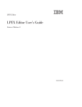
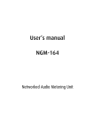
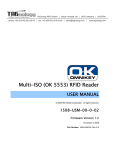
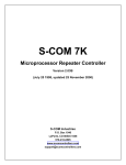
MIFARE® Reader
User Manual
idvation GmbH
Otto-Hesse-Straße 19 / T5 Phone +49 6151 4923021
D-64293 Darmstadt
Fax +49 6151 3689296
[email protected]
www.idvation.com
MIFARE® Reader
Users manual
Elatec GmbH reserves the right to make changes to its products or services or to
discontinue any product or service at any time without notice. Elatec provides customer
assistance in various technical areas, but does not have full access to data concerning the
use and applications of customer's products.
Therefore, Elatec assumes no liability and is not responsible for customer applications or
product or software design or performance relating to systems or applications
incorporating Elatec products. In addition, Elatec assumes no liability and is not
responsible for infringement of patents and/or any other intellectual or industrial property
rights of third parties, which may result from assistance provided by Elatec.
Elatec products are not designed, intended, authorized or warranted to be suitable for life
support applications or any other life critical applications that could involve potential risk of
death, personal injury or severe property or environmental damage.
With the edition of this document, all previous editions become void. Indications made in
this manual may be changed without previous notice.
Composition of the information in this manual has been done to the best of our
knowledge. Elatec does not guarantee the correctness and completeness of the details
given in this manual and may not be held liable for damages ensuing from incorrect or
incomplete information. Since, despite all our efforts, errors may not be completely
avoided, we are always grateful for your useful tips.
The installation instructions given in this manual are based on advantageous boundary
conditions. Elatec does not give any guarantee promise for perfect function in cross
environments.
idvation GmbH
Otto-Hesse-Straße 19 / T5 Phone +49 6151 4923021
D-64293 Darmstadt
Fax +49 6151 3689296
[email protected]
www.idvation.com
MIFARE® Reader
Users manual
Safety Instructions / Warning - Read before start-up!
The device may only be used for the intended purpose designed by for the manufacturer.
The operation manual should be conveniently kept available at all times for each user.
Unauthorized changes and the use of spare parts and additional devices that have not
been sold or recommended by the manufacturer may cause fire, electric shocks or
injuries. Such unauthorized measures shall exclude any liability by the manufacturer.
The liability-prescriptions of the manufacturer in the issue valid at the time of purchase are
valid for the device. The manufacturer shall not be held legally responsible for
inaccuracies, errors, or omissions in the manual or automatically set parameters for a
device or for an incorrect application of a device.
Repairs may be executed by the manufacturer only.
Only qualified personnel should carry out installation, operation, and maintenance
procedures.
Use of the device and its installation must be in accordance with national legal
requirements and local electrical codes.
When working on devices the valid safety regulations must be observed.
idvation GmbH
Otto-Hesse-Straße 19 / T5 Phone +49 6151 4923021
D-64293 Darmstadt
Fax +49 6151 3689296
[email protected]
www.idvation.com
MIFARE® Reader
Users manual
Content
1
INTRODUCTION .............................................................................................................................6
2
INSTALLATION OF NANOMF........................................................................................................7
2.1
DIMENSIONS ..................................................................................................................................7
2.2
PINNING ........................................................................................................................................7
2.3
ELECTRICAL CHARACTERISTICS ......................................................................................................8
2.4
EXTERNAL CONNECTIONS ..............................................................................................................8
2.4.1 Antenna ...................................................................................................................................8
2.4.2 Serial connection .....................................................................................................................9
2.4.3 Usage of GPIOs ......................................................................................................................9
2.4.4 Asynchronous Reset ...............................................................................................................9
2.4.5 Power supply ...........................................................................................................................9
3
SETTING UP A TERMINAL PROGRAM ......................................................................................10
4
REGISTER SET.............................................................................................................................11
4.1
EEPROM MEMORY ORGANIZATION ..............................................................................................11
4.2
STATION ID (04H) ........................................................................................................................11
4.3
PROTOCOL CONFIGURATION (05H)................................................................................................11
4.3.1 AutoStart (default 1) ..............................................................................................................12
4.3.2 ExtendID (default 0) ..............................................................................................................12
4.3.3 Multitag (default 0) ................................................................................................................12
4.4
RESET OFF TIME (07H) ................................................................................................................13
4.5
RESET RECOVERY TIME (08H) .....................................................................................................13
4.6
USER DATA (10H – 13H)...............................................................................................................15
4.7
BEEP TONE AND LENGTH (14H, NANOMF ONLY) ............................................................................15
5
COMMANDS .................................................................................................................................16
5.1
INSTRUCTION SET ........................................................................................................................17
5.2
ERROR CODES ............................................................................................................................18
5.3
TRANSPONDER SERIAL NUMBER RELATED COMMANDS ...................................................................18
5.3.1 Continuous read mode ‘c’ .....................................................................................................18
5.3.1.1
5.3.1.2
5.3.1.3
5.3.2
Multitag continuous read mode .................................................................................................. 18
AutoStart .................................................................................................................................... 18
Extended ID ............................................................................................................................... 19
Select single tag ‘s’ ...............................................................................................................19
5.3.2.1
5.3.2.2
5.3.2.3
Select a single tag...................................................................................................................... 19
Extended ID ............................................................................................................................... 19
Multiple tags ............................................................................................................................... 19
5.3.3 MultiTag selection / tag list ‘m’ ..............................................................................................20
5.4
DATA-TRANSACTION RELATED COMMANDS ....................................................................................21
5.4.1 Login (authenticate tag) ‘l’ .....................................................................................................21
5.4.1.1
5.4.1.2
Login with key stored in EEPROM ............................................................................................. 22
Login in multiple tag surroundings ............................................................................................. 22
5.4.2 Read data block ‘r’ / ‘rb’.........................................................................................................23
5.4.3 Write data block ‘w’ / ‘wb’ ......................................................................................................23
5.5
VALUE BLOCK RELATED COMMANDS ..............................................................................................25
5.5.1 Create value block ‘wv’ .........................................................................................................27
5.5.2 Read value block ‘rv’ .............................................................................................................28
5.5.3 Increment value block ‘+’ ......................................................................................................28
5.5.4 Decrement value block ‘-‘ ......................................................................................................30
5.5.5 Copy value block ‘=’ ..............................................................................................................31
5.6
SETUP-RELATED COMMANDS OF THE READER ................................................................................32
5.6.1 Read EEPROM register ‘re’ ..................................................................................................32
idvation GmbH
Otto-Hesse-Straße 19 / T5 Phone +49 6151 4923021
D-64293 Darmstadt
Fax +49 6151 3689296
[email protected]
www.idvation.com
MIFARE® Reader
Users manual
5.6.2 Write EEPROM register ‘we’ .................................................................................................32
5.6.3 Write master key ‘wm’ ...........................................................................................................33
5.7
MISCELLANEOUS COMMANDS .......................................................................................................34
5.7.1 Get Station ID ‘g’ ...................................................................................................................34
5.7.2 Antenna power off ‘poff’ ........................................................................................................34
5.7.3 Antenna power on ‘pon’ ........................................................................................................34
5.7.4 Get version ‘v’ .......................................................................................................................34
5.7.5 Reset ‘x’.................................................................................................................................35
5.7.6 Reload factory defaults ‘xf’ ....................................................................................................35
5.8
NANOMF RELATED COMMANDS ....................................................................................................36
5.8.1 Beep ‘b’ .................................................................................................................................36
5.8.2 Read GPIO ‘ir’ .......................................................................................................................36
5.8.3 Write GPIO ‘iw’ ......................................................................................................................36
5.8.4 Read GPIO1 ‘pr’ ....................................................................................................................37
5.8.5 Write GPIO1 ‘pw’ ...................................................................................................................37
6
TYPICAL DATA TRANSACTION PROCEDURE .........................................................................38
7
7.1
7.2
8
MEMORY ORGANIZATION OF TRANSPONDER CARDS .........................................................40
MIFARE® STANDARD .................................................................................................................40
MIFARE® 4K ..............................................................................................................................41
GLOSSARY ...................................................................................................................................42
idvation GmbH
Otto-Hesse-Straße 19 / T5 Phone +49 6151 4923021
D-64293 Darmstadt
Fax +49 6151 3689296
[email protected]
www.idvation.com
MIFARE® Reader
Users manual
1 Introduction
This document is the reference guide for Elatec’s MIFARE® transponder reader
family TWN3 MIFARE® and NanoMF. The readers are using the same reading
technology, so this documentation is applicable for both devices.
Elatec’s proximity reader TWN3 MIFARE® is an integrated compact reader for
reading and writing 13.56MHz ISO 14443A MIFARE® transponders. It combines
state of the art technology in a shapely and tiny housing. Reading distances of up
to 8cm (depending on transponder and environment) and various cabling options
are only two of the outstanding technical benefits offered by TWN3 mifare®.
This makes TWN3 MIFARE® as your ideal MIFARE® reading/writing device e.g.
for desktop applications.
Elatec’s reader module NanoMF is designed for integration into machines,
handheld computer or any other device. The focus has especially been set on
size, price and flexibility.
Thanks to its compact dimensions, integration directly on a PC board is possible.
Unique features are: 4 (four) user configurable ports (to be configured as input or
output). The simple proprietary ASCII protocol enables quick software
development cycles. All host communication is done via RS-232 interface.
idvation GmbH
Otto-Hesse-Straße 19 / T5 Phone +49 6151 4923021
D-64293 Darmstadt
Fax +49 6151 3689296
[email protected]
www.idvation.com
MIFARE® Reader
Users manual
2 Installation of NanoMF
This chapter covers the installation of NanoMF in an embedded environment.
2.1 Dimensions
Dimensions: 30.48mm x 25.40mm x 3.5mm (1.2” x 1” x 0.14”)
Connectors are in 2.54mm (0.1”) grid.
Schematic representation (component side)
2.2 Pinning
Pin
Name
Description
1
AntRX
Antenna receiver input
2
AntTX1
Antenna transmitter output 1
3, 20
VCC
3.3 – 5V
4, 6, 19
GND
Ground
5
AntTX2
7, 8, 9, 10
NC
11
RXD
RS-232 receiver input
12
TXD
RS-232 transmitter output
13
GPIO0
General purpose input / output 0
14
GPIO1 /
Beeper
General purpose input / output 1,
connection port for beeper
15
Reset
Asynchronous reset, active low
16
Enable
Hardware power up/down
17
GPIO2
General purpose input / output 2
18
GPIO3
General purpose input / output 3
Antenna transmitter output 2
Not connected
idvation GmbH
Otto-Hesse-Straße 19 / T5 Phone +49 6151 4923021
D-64293 Darmstadt
Fax +49 6151 3689296
[email protected]
www.idvation.com
MIFARE® Reader
Users manual
2.3 Electrical Characteristics
Frequency
13.56 MHz
Power supply
3.3 – 5.0V DC
Current consumption
RF field off:
2mA
RF field on:
Typically 80mA, depending on antenna
2.4 External Connections
The schematic below shows a typical application circuit for operating the reader
module.
2.4.1 Antenna
NanoMF requires an external antenna circuit for reading transponders. The part
values of C1 – C5 and R1 are strongly depending on the used antenna inductor.
Take the guide below as a reference for creating your own PCB antenna.
Little PCB Antenna Design Guide:
-
Antenna inductance value is usually in the range of 1 µH.
-
For antenna loop up to 40 mm diameter use 5 turns.
-
For antenna loop larger than 40 mm diameter use 3 turns.
-
Use between 1mm to 2mm track width.
-
Middle tap improves EMC compliance, but can be omitted for simple
designs.
-
All capacitors have to be chosen to create maximum field strength
(measure antenna field with an oscilloscope and the voltage induced in
some auxiliary loop; alternatively measure the module power consumption
which is maximum at optimum tuning).
idvation GmbH
Otto-Hesse-Straße 19 / T5 Phone +49 6151 4923021
D-64293 Darmstadt
Fax +49 6151 3689296
[email protected]
www.idvation.com
MIFARE® Reader
Users manual
-
C1 is used for fine tuning. Some extra capacitors may be connected in
parallel to achieve best performance.
-
Typical capacitor values: 10 pF … 470 pF. Prefer NP0/C0G ceramic
capacitors.
-
Value of R1 is usually 4.7kΩ, but this value may differ from design to
design.
For further information regarding antenna design please contact NXP in order to
receive the appropriate Application notes (Application Note Micore Reader IC
Family; Directly Matched Antenna Design)
2.4.2 Serial connection
Because NanoMF is transmitting and receiving TTL levels, it can be directly
connected to a microcontroller. If you plan to run NanoMF at a PC, an appropriate
interface converter circuit must be connected that can handle 3.0V TTL levels.
2.4.3 Usage of GPIOs
NanoMF provides four general purpose I/Os that can be configured individually.
These I/Os can be read and written via commands.
Please consider, that the GPIOs have limited current source and sink capability of
max. 25mA, and the overall current consumption of the complete module must not
exceed 150mA. An overcharge of GPIO-pins can damage the module!
A non self-oscillating beeper can also be connected to GPIO1. The tone length
and frequency can be controlled by commands.
2.4.4 Asynchronous Reset
In usual operating environments, the reset pin can be left floating. For an
asynchronous hardware reset pull the reset pin to a logic low level. NanoMF
continues operation as soon as the reset pin is released.
2.4.5 Power supply
A power supply of 3.3V – 5V must be applied between the VCC and GND pins.
Please make sure that the power supply provides a current capability of at least
100mA.
idvation GmbH
Otto-Hesse-Straße 19 / T5 Phone +49 6151 4923021
D-64293 Darmstadt
Fax +49 6151 3689296
[email protected]
www.idvation.com
MIFARE® Reader
Users manual
3 Setting up a Terminal Program
In order to establish a connection between the reader and a terminal program, the
following steps have to be done:
• Connect your reader to a PC
• Start your preferred terminal program (for Windows e.g. HyperTerminal)
• Select the serial port (e.g. COM1), where you connected the reader.
• Set up the connection speed and format: 9600 baud, 8 data bits, no parity, 1
stop bit
• Select no software handshake and no hardware handshake
idvation GmbH
Otto-Hesse-Straße 19 / T5 Phone +49 6151 4923021
D-64293 Darmstadt
Fax +49 6151 3689296
[email protected]
www.idvation.com
MIFARE® Reader
Users manual
4 Register Set
The reader has several system flags customizing its behavior. The flags are stored
non-volatile in its EEPROM. It is recommended to keep all bits labeled RFU at
logic zero to guarantee further compatibility.
Please consider, that if any register is written, the reader needs a reset so that the
changes may take effect.
Furthermore the reader is able to store up to 32 authentication keys to log in
standard MIFARE® cards internally. All keys are read only and cannot be
accessed via the interface lines.
4.1 EEPROM memory organization
Register
Access
Default value
Description
00h … 03h
RO
00h
RFU
04h
R/W
01h
Station ID
05h
R/W
01h
Protocol configuration
06h
R/W
00h
RFU, never change this register
07h
R/W
10h
Reset Off Time
08h
R/W
10h
Reset Recovery Time
09h
R/W
00h
RFU, never change this register
0Ah … 0Fh
R/W
00h
RFU, never change this register
10h … 13h
R/W
00h
User data
14h
R/W
22h
Beep tone and length (NanoMF only)
4.2 Station ID (04h)
The Station ID has principally no influence on the functional behavior of the
reader. Nevertheless it can be used to identify a reader in a multi-reader
environment.
4.3 Protocol configuration (05h)
The protocol configuration register specifies the general behavior of the reader
device.
Protocol configuration register
Bit 7
Bit 6
Bit 5
Bit 4
Bit 3
Bit 2
Bit 1
Bit 0
RFU
RFU
RFU
MultiTag
RFU
Extend
ID
RFU
Auto
Start
idvation GmbH
Otto-Hesse-Straße 19 / T5 Phone +49 6151 4923021
D-64293 Darmstadt
Fax +49 6151 3689296
[email protected]
www.idvation.com
MIFARE® Reader
Users manual
4.3.1 AutoStart (default 1)
If set the reader will start up in continuous read mode.
4.3.2 ExtendID (default 0)
If set, the unique serial number (UID) of the transponder is extended by a single
prefix byte.
This setting affects the commands continuous reading (‘c’), single tag select (‘s’)
and multi tag select (‘m’)
The values for the prefix byte are:
Prefix
Description
01h
MIFARE® Light Transponder
02h
MIFARE® Standard Transponder
03h
MIFARE® 4k Transponder
04h
MIFARE® ProX Transponder
05h
MIFARE® UltraLight Transponder
06h
MIFARE® DESFire Transponder
FFh
Unknown Transponder
4.3.3 Multitag (default 0)
The Multitag flag will enable multi tag recognition in continuous read mode. All
tags are detected and displayed. Due to the more complex search algorithm
detection speed is decreased in continuous read mode.
idvation GmbH
Otto-Hesse-Straße 19 / T5 Phone +49 6151 4923021
D-64293 Darmstadt
Fax +49 6151 3689296
[email protected]
www.idvation.com
MIFARE® Reader
Users manual
4.4 Reset Off Time (07h)
The Reset Off Time register represents the time in milliseconds, the HF-field is
switched off, after a reading attempt has finished. This register is used for the
continuous read mode (‘c’).
The higher the value of the register, the more energy can be saved. As soon as
there is a transponder in range, the field turned on permanently. Keep in mind that
increased saving of energy results in decreased detection speeds.
The image below shows the activity of the HF-field. The Reset Off Time register
has been set to 80h (128 ms):
4.5 Reset Recovery Time (08h)
The Reset Recovery Time register represents the recovery time in milliseconds
after the HF-field is turned on. This register is used for the continuous read mode
(‘c’), single tag select (‘s’) and multi tag select (‘m’) commands.
The value of the register determines the time the reader waits before any reading
attempt. Keep in mind that a higher value results in increased energy
consumption.
The image below shows the activity of the HF-field. The Reset Recovery Time
register has been set to 40h (64 ms):
idvation GmbH
Otto-Hesse-Straße 19 / T5 Phone +49 6151 4923021
D-64293 Darmstadt
Fax +49 6151 3689296
[email protected]
www.idvation.com
MIFARE® Reader
Users manual
idvation GmbH
Otto-Hesse-Straße 19 / T5 Phone +49 6151 4923021
D-64293 Darmstadt
Fax +49 6151 3689296
[email protected]
www.idvation.com
MIFARE® Reader
Users manual
4.6 User data (10h – 13h)
These registers are for free use.
4.7 Beep tone and length (14h, NanoMF only)
This register defines the beep tone (frequency) and beep length. It is only
implemented on NanoMF.
Beep tone and length register
Bit 7
Bit 6
Bit 5
Bit 4
Bit 3
Bit 2
Length
Bit 1
Tone
The beep tone code selects a predefined frequency from the table below:
Tone[3:0]
0000
0001
0010
0011
0100
0101
0110
0111
1000
1001
1010
1011
1100
1101
1110
1111
Frequency
523Hz
554Hz
587Hz
622Hz
659Hz
699Hz
739Hz
784Hz
831Hz
880Hz
932Hz
988Hz
Reserved
Reserved
Reserved
Reserved
Standard pitch (Vienna scale)
C
Cis
D
Dis
E
F
Fis
G
Gis
A
Ais
H
The following formula defines the beep length:
BeepLength = (Length[3:0] + 1) x 62.5ms
Examples:
Length[3:0]
0000
0001
0111
1111
BeepLength
62.5ms
125ms
500ms
1000ms
idvation GmbH
Otto-Hesse-Straße 19 / T5 Phone +49 6151 4923021
D-64293 Darmstadt
Fax +49 6151 3689296
[email protected]
www.idvation.com
Bit 0
MIFARE® Reader
Users manual
5 Commands
Every time the reader is powered up, a startup message is displayed. On the
terminal screen this should look like this:
Mifare 1.07<CR><LF>
The reader is now ready for reception of commands. By default, the reader starts
in continuous reading mode, this means the reader is scanning for transponders
and prints the present UIDs.
The reader is using a proprietary ASCII-protocol, which has been designed for
easy handling. Data is transmitted in hexadecimal notation, i.e. 5E.
Please note that pseudo-tetrade values always must be submitted in capital
letters, e.g. 1234ABCD
Commands must be submitted in lower-case letters, e.g. we071F
idvation GmbH
Otto-Hesse-Straße 19 / T5 Phone +49 6151 4923021
D-64293 Darmstadt
Fax +49 6151 3689296
[email protected]
www.idvation.com
MIFARE® Reader
Users manual
5.1 Instruction set
Command
Implemented on
TWN3
mifare®
Description
NanoMF
‘+’
Increment value block
‘-‘
Decrement value block
‘=’
Copy value block
‘b’
Beep
‘c’
Continuous read mode
‘g’
Get station ID
‘ir’/’iw’
Read / write GPIO0…3
‘l’
Login (authenticate tag)
‘m’
MultiTag select / tag list
‘poff’
Antenna power off
‘pon’
Antenna power on
‘pr’/’pw’
Read / write GPIO1
‘r’/‘rb’
Read data block
‘re’
Read EEPROM register
‘rv’
Read value block
‘s’
Select single tag
‘v’
Get version
‘w’/‘wb’
Write data block
‘we’
Write EEPROM register
‘wm’
Write master key
‘wv’
Write value block
‘x’
Reset
‘xf’
Reload factory defaults
idvation GmbH
Otto-Hesse-Straße 19 / T5 Phone +49 6151 4923021
D-64293 Darmstadt
Fax +49 6151 3689296
[email protected]
www.idvation.com
MIFARE® Reader
Users manual
5.2 Error Codes
Following table shows an overview of all error messages of the reader device.
Error Code
Description
‘?<CR><LF>’ Unknown command
‘E<CR><LF>’ Invalid key format
‘F<CR><LF>’ General failure
‘I<CR><LF>’ Invalid value block (block does not match the value format)
‘N<CR><LF>’ No tag in the field
‘O<CR><LF>’ Operation mode failure
‘X<CR><LF>’ Error during value operation
5.3 Transponder serial number related commands
5.3.1 Continuous read mode ‘c’
The reader device reads and displays serial numbers continuously while one or
more tags remain in the field. This command stops as soon as any character is
sent to the reader.
The reader supports different tag types at the same time. In order to increase the
reading performance, switch to single tag mode. If more than one tag shall be
detected at the same time, the MultiTag flag must be activated. The response data
length depends on the tag type.
Command: ‘c’
Answer
Answer
Description
data<CR><LF> Serial number (UID, n bytes)
5.3.1.1 Multitag continuous read mode
If the MultiTag flag is set in the Protocol Configuration register, the reader reads
multiple tags continuously.
5.3.1.2 AutoStart
The continuous read mode is started automatically. The AutoStart flag must be set
in the Protocol Configuration register.
idvation GmbH
Otto-Hesse-Straße 19 / T5 Phone +49 6151 4923021
D-64293 Darmstadt
Fax +49 6151 3689296
[email protected]
www.idvation.com
MIFARE® Reader
Users manual
5.3.1.3 Extended ID
If ExtendID is activated in the Protocol Configuration register, a prefix byte extends
the serial number (UID). For more information refer to the Protocol Configuration
register.
5.3.2 Select single tag ‘s’
This command selects a single tag in the antenna field. It shall only be used in
single tag environments. In case of success the command returns the UID of the
selected card. The length of the UID is detected automatically.
As soon as a transponder has been selected, it is ready for further data
transactions, e.g. authentication, read block or write block.
Command: ‘s’
Answer
Answer
Description
data<CR><LF> Serial number (UID, n bytes)
‘N<CR><LF>’
Error: No tag in the field
5.3.2.1 Select a single tag
No previous continuous read is required. The command executes an automatic
field reset.
5.3.2.2 Extended ID
If ExtendID is activated in the Protocol Configuration register, a prefix byte extends
the serial number (UID). For more information refer to the Protocol Configuration
register.
5.3.2.3 Multiple tags
This command is designed for fast access of a single tag in the field. In multiple
tag environments the ‘m’ instruction has to be used instead.
idvation GmbH
Otto-Hesse-Straße 19 / T5 Phone +49 6151 4923021
D-64293 Darmstadt
Fax +49 6151 3689296
[email protected]
www.idvation.com
MIFARE® Reader
Users manual
5.3.3 MultiTag selection / tag list ‘m’
This command detects several tags at the same time. It replaces the fast select
command (‘s’) in multiple tag surroundings. The MultiTag list command lists all
present tags with their serial numbers. Use the MultiTag select command to select
a single tag. Each tag has to be selected separately.
After selection, the transponder is ready for further data transactions, e.g.
authentication, read block or write block.
Keep in mind that each transponder consumes its individual amount of energy,
provided by the reader. Due to the limited availability of emitted energy, the
operating distance is decreased, the more transponders are present. Principally
the operating distance depends on the used transponders, the total amount of
transponders and the ambient conditions, e.g. if metal is surrounding the reader.
Command: ‘m<CR>’ / ‘m[UID]<CR>’
Command
‘m<CR>’
Description
List all present tags
‘m[UID]<CR>’ Select tag by its UID
Answer
Answer
Description
data<CR><LF> Serial number (UID, n bytes)
‘N<CR><LF>’
Error: No tag in the field
Examples
Command
‘m<CR>’
Answer
Description
044A3A11FC1E80
First card
56AB3798
Second card
02
Number of detected tags
‘m56AB3798000000<CR>’ 56AB3798
Second tag selected
Note:
The MultiTag selection command always requires a 7 byte UID. If the UID of the
desired transponder possesses only 4 bytes, the passed UID must be filled up with
zeros – see the example above.
idvation GmbH
Otto-Hesse-Straße 19 / T5 Phone +49 6151 4923021
D-64293 Darmstadt
Fax +49 6151 3689296
[email protected]
www.idvation.com
MIFARE® Reader
Users manual
5.4 Data-transaction related commands
5.4.1 Login (authenticate tag) ‘l’
This command performs an authentication into a specific sector of a MIFARE®
transponder. Only one transponder and only sector can be accessed at the same
time. Prior access, the transponder must be selected by either single tag or
MultiTag selection commands.
For authentication into a sector, the matching login key is needed. The key may
either be entered by command, or can be stored in the readers’ EEPROM. The
reader is able to store up to 32 master keys.
Command: ‘l[Sector][KeyType][Key / <CR>]’
Parameters
Description
[Sector]
Sector number, valid range 00h – 3Fh
[KeyType]
AAh: authenticate with key type A
FFh:
authenticate
FFFFFFFFFFFFh
with
key
type
A,
transport
key
BBh: authenticate with key type B
10h … 2Fh: authenticate with stored key type A (00h … 1Fh)
30h … 4Fh: authenticate with stored key type B (00h … 1Fh)
[Key / <CR>] Enter key manually (6 bytes) or tell the reader to login with a
transport key by submitting a carriage return <CR> (1 byte)
Answer
Answer
Description
‘L<CR><LF>’ Login success
‘E<CR><LF>’ Error: invalid key format
‘F<CR><LF>’ Error: general failure
‘N<CR><LF>’ Error: no tag in the field or the tag does not respond
idvation GmbH
Otto-Hesse-Straße 19 / T5 Phone +49 6151 4923021
D-64293 Darmstadt
Fax +49 6151 3689296
[email protected]
www.idvation.com
MIFARE® Reader
Users manual
Examples
Command
Description
‘l01AA<CR>’
Authenticate into sector 01 using transport key type A
A0A1A2A3A4A5h
‘l02BB<CR>’
Authenticate into sector 02 using transport key type B
B0B1B2B3B4B5h
‘l03FF<CR>’
Authenticate into sector 03 using transport key type A
FFFFFFFFFFFFh
‘l04AA1234567890AB’
Authenticate into sector 04 using specified key type A
1234567890ABh
‘l0510’
Authenticate into sector 05 using EEPROM key 0, key
type A
‘l0637’
Authenticate into sector 06 using EEPROM key 7, key
type B
5.4.1.1 Login with key stored in EEPROM
The reader supports the storage of up to 32 authentication keys in its internal
EEPROM. To access one of these keys, the user must specify the desired key by
passing the valid information in the parameter list of the login command.
Principally every stored key may act either as key A or key B, the selection is done
via parameter list.
Keys type A can be accessed by passing KeyType range 10h … 2Fh; in order to
log in with a stored key type B, the value must be range 30h … 4F.
5.4.1.2 Login in multiple tag surroundings
In order to log into different tags, list all present tags first and then select the
desired tag. After that, perform the login procedure.
idvation GmbH
Otto-Hesse-Straße 19 / T5 Phone +49 6151 4923021
D-64293 Darmstadt
Fax +49 6151 3689296
[email protected]
www.idvation.com
MIFARE® Reader
Users manual
5.4.2 Read data block ‘r’ / ‘rb’
This command reads an entire data block (16 Bytes) of a transponder. The range
of valid block addresses depends on the used transponder. Keep in mind that any
read- or write access requires a successful login into the respective sector.
Command: ‘r[BlockAddr]’ / ‘rb[BlockAddr]’
Answer
Answer
Description
Data<CR><LF> Block data
‘F<CR><LF>’
Error: read failure
‘N<CR><LF>’
Error: no tag in the field, or the tag does not respond
‘O<CR><LF>’
Error: Operation mode failure; the block address of the ‘r’
command is higher than 40h, use the ‘rb’ command instead.
Example
Command
r08
Description
Reads block 08 (sector 02, block 00)
5.4.3 Write data block ‘w’ / ‘wb’
This command writes an entire data block (16 Bytes) to a transponder. The range
of valid block addresses depends on the used transponder. A read after write is
done automatically to ensure data integrity. Keep in mind that any read- or write
access requires a successful login into the respective sector.
Command: ‘w[BlockAddr]’ / ‘wb[BlockAddr]’
Answer
Answer
Description
Data<CR><LF> Block data
‘F<CR><LF>’
Error: write failure
‘N<CR><LF>’
Error: no tag in the field, or the tag does not respond
‘O<CR><LF>’
Error: Operation mode failure; the block address of the ‘w’
command is higher than 40h, use the ‘wb’ command instead.
Example
Command
idvation GmbH
Otto-Hesse-Straße 19 / T5 Phone +49 6151 4923021
D-64293 Darmstadt
Fax +49 6151 3689296
[email protected]
www.idvation.com
Description
MIFARE® Reader
Users manual
w08000102030405060708090A0B0C0D0E0F Writes data
000102030405060708090A0B0C0D0E0F
to block 08 (sector 02, block 00)
idvation GmbH
Otto-Hesse-Straße 19 / T5 Phone +49 6151 4923021
D-64293 Darmstadt
Fax +49 6151 3689296
[email protected]
www.idvation.com
MIFARE® Reader
Users manual
5.5 Value block related commands
A sector of a MIFARE® transponder may contain so-called ‘value blocks’. A value
block is a usual data block, where the information is stored in a certain format.
Special MIFARE® commands like increment or decrement may be applied to such
a block, e.g. for electronic purse functionality. A value block contains 4 bytes user
data, the remaining 12 bytes are processed internally by the MIFARE®
transponder for increased data integrity.
A value block is formatted as follows:
Byte
Data
0
1
2
Value
3
4
5
6
7
Value
8
9
10
Value
11
12
13
14
15
A
A
A
A
The value data is stored three times: twice non-inverted and once inverted. The
lowest significant byte is stored in the lowest address byte. The last four bytes are
for internal use and shall not be altered.
The following diagram shows the typical command-flow in order to work with
MIFARE® value blocks:
idvation GmbH
Otto-Hesse-Straße 19 / T5 Phone +49 6151 4923021
D-64293 Darmstadt
Fax +49 6151 3689296
[email protected]
www.idvation.com
MIFARE® Reader
Users manual
Select
Transponder
‚s’ / ‚m’
Log into
sector ‚l’
Create value
block ‚wv’
Increment ‚+’
Decrement ‚-‚
idvation GmbH
Otto-Hesse-Straße 19 / T5 Phone +49 6151 4923021
D-64293 Darmstadt
Fax +49 6151 3689296
[email protected]
www.idvation.com
Copy ‚=’
Read value
block ‚rv’
MIFARE® Reader
Users manual
5.5.1 Create value block ‘wv’
Use this command to format a common data block as a value block. The range of
valid block addresses depends on used transponder type. You must log into the
respective sector before this command can be executed.
Command: ‘wv[BlockAddr][Value]’
Parameters
Description
[BlockAddr]
Block address
[Value]
Initial value stored on the value block (4 bytes).
The value is stored signed (most significant bit). Negative values
are stored in 2’s complement format.
Answer
Answer
Description
Data<CR><LF> Written value
‘F<CR><LF>’
Error: write failure
‘I<CR><LF>’
Error: invalid block format
Examples
Command
Description
wv0800000000 Formats block 08 as a value block. Initial value: 00000000h
wv0912345678 Formats block 09 as a value block. Initial value: 12345678h
wv0AFFFFFFFE Formats block 0A as a value block. Initial value: FFFFFFFFEh (-2)
idvation GmbH
Otto-Hesse-Straße 19 / T5 Phone +49 6151 4923021
D-64293 Darmstadt
Fax +49 6151 3689296
[email protected]
www.idvation.com
MIFARE® Reader
Users manual
5.5.2 Read value block ‘rv’
Use this command to read a value block. This command checks if data of
specified block is stored in value format. You must log into the respective sector
before this command can be executed.
Command: ‘rv[BlockAddr]’
Parameters
Description
[BlockAddr]
Block address
Answer
Answer
Description
Data<CR><LF> Value of block
‘F<CR><LF>’
Error: read failure
‘I<CR><LF>’
Error: invalid block format
Example
Command
rv08
Description
Reads value block 08
5.5.3 Increment value block ‘+’
Use this command to increment a value block with a defined value. A read after
increment is performed automatically. The command fails if the specified block is
not formatted as value block. You must log into the respective sector before this
command can be executed.
Command: ‘+[BlockAddr][Value]’
Parameters
Description
[BlockAddr]
Block address (1 byte)
[Value]
Value to be added (4 bytes)
Answer
Answer
Description
Data<CR><LF> Value of block
‘F<CR><LF>’
Error: read failure
idvation GmbH
Otto-Hesse-Straße 19 / T5 Phone +49 6151 4923021
D-64293 Darmstadt
Fax +49 6151 3689296
[email protected]
www.idvation.com
MIFARE® Reader
Users manual
‘I<CR><LF>’
Error: invalid block format
‘X<CR><LF>’
Error: Bad value operation, e.g. sign overflow
idvation GmbH
Otto-Hesse-Straße 19 / T5 Phone +49 6151 4923021
D-64293 Darmstadt
Fax +49 6151 3689296
[email protected]
www.idvation.com
MIFARE® Reader
Users manual
Examples
Command
Description
+0800000001
Increments block 08 by 00000001h
+0812345678
Increments block 08 by 12345678h
5.5.4 Decrement value block ‘-‘
Use this command to decrement a value block with a defined value. A read after
decrement is performed automatically. The command fails if the specified block is
not formatted as value block. You must log into the respective sector before this
command can be executed.
Command: ‘-[BlockAddr][Value]’
Parameters
Description
[BlockAddr]
Block address (1 byte)
[Value]
Value to be subracted (4 bytes)
Answer
Answer
Description
Data<CR><LF> Value of block
‘F<CR><LF>’
Error: read failure
‘I<CR><LF>’
Error: invalid block format
‘X<CR><LF>’
Error: Bad value operation, e.g. sign overflow
Examples
Command
Description
-0800000001
Decrements block 08 by 00000001h
-0812345678
Decrements block 08 by 12345678h
idvation GmbH
Otto-Hesse-Straße 19 / T5 Phone +49 6151 4923021
D-64293 Darmstadt
Fax +49 6151 3689296
[email protected]
www.idvation.com
MIFARE® Reader
Users manual
5.5.5 Copy value block ‘=’
Use this command to copy a value block to another value block of the same
sector. A read after copy is performed automatically. The command fails if one of
the specified blocks is not in value format. You must log into the respective sector
before this command can be executed.
Command: ‘=[SourceBlock][TargetBlock]’
Parameters
Description
[SourceBlock] Source block address (1 byte)
[TargetBlock] Target block address (1 byte)
Answer
Answer
Description
Data<CR><LF> New value of target block
‘F<CR><LF>’
Error: general failure
‘I<CR><LF>’
Error: invalid block format
Examples
Command
Description
=0809
Copy value block 08 to block 09
=080A
Copy value block 08 to block 0A
idvation GmbH
Otto-Hesse-Straße 19 / T5 Phone +49 6151 4923021
D-64293 Darmstadt
Fax +49 6151 3689296
[email protected]
www.idvation.com
MIFARE® Reader
Users manual
5.6 Setup-related commands of the reader
5.6.1 Read EEPROM register ‘re’
Use this command to read any internal reader EEPROM register. The register
address must be range 00h … 14h.
Command: ‘re[EERegAddr]’
Answer
Answer
Description
Data<CR><LF> EEPROM data (1 byte)
Example
Command
re04
Description
Reads register 04 (Station ID)
5.6.2 Write EEPROM register ‘we’
Use this command to write any internal reader EEPROM register. The register
address must be range 04h … 14h. A read after write check is performed
automatically.
Command: ‘we[EERegAddr][Data]’
Answer
Answer
Description
Data<CR><LF> EEPROM data (1 byte)
‘F<CR><LF>’
Error: read after write failure
Example
Command
we0415
Description
Writes 15h to register 04 (Station ID)
idvation GmbH
Otto-Hesse-Straße 19 / T5 Phone +49 6151 4923021
D-64293 Darmstadt
Fax +49 6151 3689296
[email protected]
www.idvation.com
MIFARE® Reader
Users manual
5.6.3 Write master key ‘wm’
Use this command to store a MIFARE® authentication key into the EEPROM of
the reader. Up to 32 keys can be stored in the reader. The key locations are writeonly, so the keys can’t be read back. If the writing process fails, the reader returns
a error message instead.
Each key is 6 bytes long and is stored redundantly to increase data integrity.
Command: ‘wm[KeyNumber][Key]’
Answer
Answer
Description
Key<CR><LF> Written key
‘F<CR><LF>’ Error: write failure
Example
Command
Description
wm1A1234567890AB Writes key 1234567890AB to location 1Ah
idvation GmbH
Otto-Hesse-Straße 19 / T5 Phone +49 6151 4923021
D-64293 Darmstadt
Fax +49 6151 3689296
[email protected]
www.idvation.com
MIFARE® Reader
Users manual
5.7 Miscellaneous commands
5.7.1 Get Station ID ‘g’
Use this command to retrieve the station ID of the reader.
Command: ‘g’
Answer
Answer
Description
Data<CR><LF> Station ID of the reader (1 byte)
5.7.2 Antenna power off ‘poff’
Use this command to turn off the HF-field and save energy. All present tags in the
antenna field are powered down and reset.
Command: ‘poff’
Answer
Answer
Description
‘P<CR><LF>’ Power off / on command performed
5.7.3 Antenna power on ‘pon’
Use this command to turn on the HF-field manually. If a tag-related command is
submitted, the HF-field is also turned on.
Command: ‘pon’
Answer
Answer
Description
‘P<CR><LF>’ Power off / on command performed
5.7.4 Get version ‘v’
Use this command to receive the current version of the reader.
Command: ‘v’
Answer
Answer
‘Mifare 1.07<CR><LF>’
Description
Version string
idvation GmbH
Otto-Hesse-Straße 19 / T5 Phone +49 6151 4923021
D-64293 Darmstadt
Fax +49 6151 3689296
[email protected]
www.idvation.com
MIFARE® Reader
Users manual
5.7.5 Reset ‘x’
Use this command to perform a software reset of the reader.
Command: ‘x’
Answer
Answer
‘Mifare 1.07<CR><LF>’
Description
Version string
5.7.6 Reload factory defaults ‘xf’
Use this command to reload the factory defaults of the reader. A software reset is
performed automatically.
Command: ‘xf’
Answer
Answer
‘Mifare 1.07<CR><LF>’
Description
Version string
idvation GmbH
Otto-Hesse-Straße 19 / T5 Phone +49 6151 4923021
D-64293 Darmstadt
Fax +49 6151 3689296
[email protected]
www.idvation.com
MIFARE® Reader
Users manual
5.8 NanoMF related commands
5.8.1 Beep ‘b’
Use this command to perform a beep. Tone length and frequency are depending
on the settings in the Beep tone and length register. The command answers with
the value written in the Beep tone and length register.
Command: ‘b’
Example
Answer
‘22’
Description
Sounds a beep with tone length 125ms and frequency
587Hz
5.8.2 Read GPIO ‘ir’
Use this command to read a specified GPIO. The GPIO is switched to input prior
reading.
Command: ‘ir[GPIONumber]’
Answer
Answer
Description
Data<CR><LF> Status of specified GPIO: 00 means Low; 01 means High.
Example
Command
‘ir02’
Description
Returns status of GPIO2.
5.8.3 Write GPIO ‘iw’
Use this command to write a specified GPIO. The GPIO is switched to output prior
writing. Please consider the reader’s maximum current source and sink capability!
Command: ‘iw[GPIONumber][Status]’
Answer
Answer
Description
Data<CR><LF> Status of specified GPIO: 00 means Low; 01 means High.
idvation GmbH
Otto-Hesse-Straße 19 / T5 Phone +49 6151 4923021
D-64293 Darmstadt
Fax +49 6151 3689296
[email protected]
www.idvation.com
MIFARE® Reader
Users manual
Example
Command
Description
‘iw0201’
Sets GPIO2 to logical state High
‘iw0300’
Sets GPIO3 to logical state Low
5.8.4 Read GPIO1 ‘pr’
Use this command to read GPIO1. GPIO1 is switched to input prior reading. The
command has the same effect as command ‘ir01’. It has been implemented in
order to adhere backward compatibility.
Command: ‘pr’
Answer
Answer
Description
Data<CR><LF> Status of GPIO1: 00 means Low; 01 means High.
5.8.5 Write GPIO1 ‘pw’
Use this command to write GPIO1. GPIO1 is switched to output prior writing.
Please consider the reader’s maximum current source and sink capability! The
command has the same effect as command ‘iw010X’. It has been implemented
in order to adhere backward compatibility.
Command: ‘pw[Status]’
Answer
Answer
Description
Data<CR><LF> Status of GPIO1: 00 means Low; 01 means High.
idvation GmbH
Otto-Hesse-Straße 19 / T5 Phone +49 6151 4923021
D-64293 Darmstadt
Fax +49 6151 3689296
[email protected]
www.idvation.com
MIFARE® Reader
Users manual
6 Typical data transaction procedure
The following diagram shows the typical command-flow in order to access the data
area of a MIFARE® transponder:
idvation GmbH
Otto-Hesse-Straße 19 / T5 Phone +49 6151 4923021
D-64293 Darmstadt
Fax +49 6151 3689296
[email protected]
www.idvation.com
MIFARE® Reader
Users manual
idvation GmbH
Otto-Hesse-Straße 19 / T5 Phone +49 6151 4923021
D-64293 Darmstadt
Fax +49 6151 3689296
[email protected]
www.idvation.com
MIFARE® Reader
Users manual
7 Memory Organization of Transponder Cards
7.1 MIFARE® Standard
A MIFARE® Standard 1k transponder consists of 16 sectors. Each sector is
organized in four data blocks. A data block stores 16 bytes of data. The following
table shows the memory organization of a MIFARE® Standard card:
Sector address
Block addresses
00h
03h
02h
01h
00h
01h
07h
06h
05h
04h
02h
0Bh
0Ah
09h
08h
03h
0Fh
0Eh
0Dh
0Ch
04h
13h
12h
11h
10h
05h
17h
16h
15h
14h
06h
1Bh
1Ah
19h
18h
07h
1Fh
1Eh
1Dh
1Ch
08h
23h
22h
21h
20h
09h
27h
26h
25h
24h
0Ah
2Bh
2Ah
29h
28h
0Bh
2Fh
2Eh
2Dh
2Ch
0Ch
33h
32h
31h
30h
0Dh
37h
36h
35h
34h
0Eh
3Bh
3Ah
39h
38h
0Fh
3Fh
3Eh
3Dh
3Ch
idvation GmbH
Otto-Hesse-Straße 19 / T5 Phone +49 6151 4923021
D-64293 Darmstadt
Fax +49 6151 3689296
[email protected]
www.idvation.com
MIFARE® Reader
Users manual
7.2 MIFARE® 4k
A MIFARE® 4k transponder consists of 40 sectors. In contrast to the MIFARE®
standard 1k transponder, the 4k version has a different memory organization,
shown in the following table:
800h –
FFFh
000h – 7FFh
Bytes
Sector
Block
addresses
Login
sector
Sector
Block
addresses
Login
sector
00h
00h – 03h
00h
10h
40h – 43h
10h
01h
04h – 07h
01h
11h
44h – 47h
11h
02h
08h – 0Bh
02h
12h
48h – 4Bh
12h
03h
0Ch – 0Fh
03h
13h
4Ch – 4Fh
13h
04h
10h – 13h
04h
14h
50h – 53h
14h
05h
14h – 17h
05h
15h
54h – 57h
15h
06h
18h – 1Bh
06h
16h
58h – 5Bh
16h
07h
1Ch – 1Fh
07h
17h
5Ch – 5Fh
17h
08h
20h – 23h
08h
18h
60h – 63h
18h
09h
24h – 27h
09h
19h
64h – 67h
19h
0Ah
28h – 2Bh
0Ah
1Ah
68h – 6Bh
1Ah
0Bh
2Ch – 2Fh
0Bh
1Bh
6Ch – 6Fh
1Bh
0Ch
30h – 33h
0Ch
1Ch
70h – 73h
1Ch
0Dh
34h – 37h
0Dh
1Dh
74h – 77h
1Dh
0Eh
38h – 3Bh
0Eh
1Eh
78h – 7Bh
1Eh
0Fh
3Ch – 3Fh
0Fh
1Fh
7Ch – 7Fh
1Fh
20h
80h – 8Fh
20h
24h
C0h – CFh
30h
21h
90h – 9Fh
24h
25h
D0h – DFh
34h
22h
A0h – Afh
28h
26h
E0h – EFh
38h
23h
B0h – BFh
2Ch
27h
F0h – FFh
3Ch
idvation GmbH
Otto-Hesse-Straße 19 / T5 Phone +49 6151 4923021
D-64293 Darmstadt
Fax +49 6151 3689296
[email protected]
www.idvation.com
MIFARE® Reader
Users manual
8 Glossary
Block
A block contains usually 16 data bytes
HF-field
An alternating magnetic field emitted by the reader. The
frequency is typically 13.56MHz
Key type
A sector can be logged into by use of two different keys, A or B.
The access rights of each data block depend on individual access
conditions which can be assigned to the respective key.
Transport key
This key is stored by the manufacturer for transport purposes.
The transport keys are usually A0A1A2A3A4A5h (type A),
B0B1B2B3B4B5h (type B) or FFFFFFFFFFFFh (type A)
Sector
A sector contains 4 or 16 blocks. The number of sectors depends
on the transponder type.
UID
Abbreviation for Unique Identifier. The UID of a MIFARE®
transponder is factory programmed and cannot be changed.
Value block
MIFARE® data block, that is formatted in a manner to perform
MIFARE® value manipulation commands.
idvation GmbH
Otto-Hesse-Straße 19 / T5 Phone +49 6151 4923021
D-64293 Darmstadt
Fax +49 6151 3689296
[email protected]
www.idvation.com