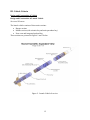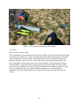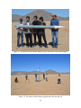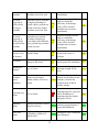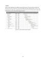
1
Flight Readiness Review Report NASA Student Launch Mini-MAV Competition 2014-15 1000 W. Foothill Blvd. Glendora, CA 91741 Project Λscension March 16, 2015 1 General Information ........................................................................................................................ 7 School Information ..................................................................................................................... 7 Adult Educators .......................................................................................................................... 7 Safety Officer .............................................................................................................................. 7 Student Team Leader .................................................................................................................. 7 Team Members and Proposed Duties ......................................................................................... 7 NAR/ TRA Sections ................................................................................................................... 8 I. Summary of FRR Report ............................................................................................................. 9 Team Summary ........................................................................................................................... 9 Launch Vehicle Summary........................................................................................................... 9 AGSE/ Payload Summary........................................................................................................... 9 II. Changes made since CDR ........................................................................................................ 10 Changes to Vehicle Criteria ...................................................................................................... 10 Changes to AGSE/ Payload Criteria ......................................................................................... 10 Changes to Project Plan ............................................................................................................ 11 CDR Feedback .......................................................................................................................... 11 III. Vehicle Criteria ....................................................................................................................... 12 Design and Construction of Vehicle ......................................................................................... 12 Design and Construction of Launch Vehicle ........................................................................ 12 Flight Reliability and Confidence ......................................................................................... 19 Test Data and Analysis ......................................................................................................... 20 Workmanship ........................................................................................................................ 21 Safety and Failure Analysis .................................................................................................. 21 Full-Scale Launch Test Results ............................................................................................ 21 Mass Report .......................................................................................................................... 28 Recovery System ...................................................................................................................... 28 Recovery System Robustness ............................................................................................... 28 Parachute Size, Attachment, Deployment, and Test Results ................................................ 38 Safety and Failure Analysis .................................................................................................. 39 Mission Performance Predictions ............................................................................................. 40 Mission Performance Criteria ............................................................................................... 40 Flight Profile Simulations ..................................................................................................... 41 Scale Modeling Results......................................................................................................... 42 Stability Margin .................................................................................................................... 43 2 Kinetic Energy at Various Phases ......................................................................................... 44 Drift ....................................................................................................................................... 44 Verification ............................................................................................................................... 45 Requirements Verification and Verification Statements ...................................................... 45 Safety and Environment ............................................................................................................ 51 Safety and Mission Assurance Analysis ............................................................................... 51 Updated Personnel Hazards .................................................................................................. 54 Environmental Concerns ....................................................................................................... 56 AGSE Integration...................................................................................................................... 57 Integration of AGSE with Launch Vehicle ........................................................................... 58 Compatibility of Elements .................................................................................................... 62 Payload Housing Integrity .................................................................................................... 65 Integration Demonstration .................................................................................................... 65 IV. AGSE/ Payload Criteria .......................................................................................................... 70 Experiment Concept.................................................................................................................. 70 Creativity and Originality ..................................................................................................... 70 Uniqueness and Significance ................................................................................................ 70 Science Value............................................................................................................................ 70 AGSE/ Payload Objectives and Mission Success Criteria ................................................... 70 AGSE/ Payload Design ............................................................................................................. 71 Design and Construction of the AGSE/ Payload .................................................................. 71 Precision of Instrumentation ................................................................................................. 88 Workmanship ........................................................................................................................ 88 Verification ............................................................................................................................... 89 AGSE/ Payload Requirements Verification and Verification Statements ............................ 89 Safety and Environment (AGSE/ Payload)............................................................................... 97 Safety and Mission Assurance Analysis ............................................................................... 97 Personnel Hazards ............................................................................................................... 101 Environmental Concerns ..................................................................................................... 101 V. Launch Operations Procedures .............................................................................................. 102 Checklist ................................................................................................................................. 102 Avionics Preparation ........................................................................................................... 102 Nose Cone Preparation ....................................................................................................... 102 Recovery Preparation .......................................................................................................... 103 3 Motor Preparation ............................................................................................................... 104 Setup on Launcher .............................................................................................................. 104 Igniter Installation ............................................................................................................... 104 Launch Procedure ............................................................................................................... 104 Troubleshooting .................................................................................................................. 105 Post-Flight Inspection ......................................................................................................... 105 Safety and Quality Assurance ................................................................................................. 106 Data Demonstrating Risks are at Acceptable Levels .......................................................... 106 Risk Assessment for Launch Operations ............................................................................ 108 Environmental Concerns ..................................................................................................... 110 Individual Responsible for Maintaining Safety, Quality, and Procedures Checklist ......... 110 VI. Project Plan ........................................................................................................................... 111 Status of Activities and Schedule ........................................................................................... 111 Budget Plan ......................................................................................................................... 111 Funding Plan ....................................................................................................................... 115 Timeline .............................................................................................................................. 116 Educational Engagement .................................................................................................... 118 VII. Conclusion ........................................................................................................................... 122 Table 1: Team Member Duties ...................................................................................................... 7 Table 2: Structural Elements ........................................................................................................ 13 Table 3: Test Launch Overview .................................................................................................... 22 Table 4: Mass Report ................................................................................................................... 28 Table 5: Recovery Subsystem Components ................................................................................ 29 Table 6: Parachute Sizes and Descent Rates................................................................................ 30 Table 7: Recovery System Electrical Components ....................................................................... 32 Table 8: Recovery Failure Modes ................................................................................................. 39 Table 9: Kinetic Energy of each Rocket Section ......................................................................... 44 Table 10: Drift from Launch Pad (all sections) ........................................................................... 45 Table 11: Launch Vehicle Requirements and Verification.......................................................... 45 Table 12: Recovery Requirements and Verification .................................................................... 49 Table 13: Vehicle Failure Modes .................................................................................................. 51 Table 14: Tool Safety.................................................................................................................... 55 Table 15: Environmental Hazards ................................................................................................ 56 Table 16: Payload Containment Components............................................................................... 58 Table 17: Design features and justification .................................................................................. 60 Table 18: Scientific Objectives & Success Criteria ...................................................................... 71 Table 19: Subsystem Level Functional Requirements.................................................................. 73 Table 20: Body Subsystem Component Overview ....................................................................... 74 4 Table 21: Camera Subsystem Component Overview ................................................................... 80 Table 22: Payload Retrieval Subsystem Component Overview ................................................... 81 Table 23: AGSE Requirement Summary...................................................................................... 87 Table 24: AGSE System Level Verification ................................................................................. 91 Table 25: AGSE Failure Analysis................................................................................................. 97 Table 26: Tripoli minimum distance table .................................................................................. 106 Table 27: Launch Operations Risk Assessment.......................................................................... 108 Table 28: Budget ......................................................................................................................... 111 Table 29: Funding Plan ............................................................................................................... 115 Figure 1: Organizational flow chart ................................................................................................ 8 Figure 2: Launch Vehicle Overview ............................................................................................ 12 Figure 3: Launch Vehicle Overview ............................................................................................ 13 Figure 4: Booster Section............................................................................................................. 14 Figure 5: AeroPack Retainer ........................................................................................................ 15 Figure 6: Middle Section of Launch Vehicle ............................................................................... 16 Figure 7: Main Parachute Piston .................................................................................................. 17 Figure 8: Payload Containment Bay ............................................................................................ 18 Figure 9: The Rocket Owls holding the launch vehicle which is prepped for launch .................. 22 Figure 10: The launch vehicle minutes before take-off ................................................................ 23 Figure 11: The payload containment section after landing ........................................................... 24 Figure 12: The booster section after landing ................................................................................ 24 Figure 13: The avionics and main bay after landing..................................................................... 25 Figure 14: The Rocket Owls with the launch vehicle at the site for the second launch ............... 26 Figure 15: The launch vehicle almost prepped and ready for take-off ......................................... 26 Figure 16: The launch vehicle sections under their respective parachutes ................................... 27 Figure 17: The booster, avionics, and main bay after landing ...................................................... 27 Figure 18: Recovery Deployment ................................................................................................ 29 Figure 19: Electrical schematic for the avionics bay altimeters ................................................... 33 Figure 20: The recovery electronics mounted and wired inside the avionics bay. ....................... 33 Figure 21: The switches for the avionics recovery electronics in the airframe. ........................... 34 Figure 22: The avionics within the airframe of the launch vehicle .............................................. 34 Figure 23: Battery retention for the avionics electronics .............................................................. 35 Figure 24: The electrical schematics for the containment section altimeters ............................... 36 Figure 25: The final assembly of the containment section altimeters with battery retention ....... 36 Figure 26: The containment section switches as well as connectors for ejection charges ........... 37 Figure 27: Piston Ejection Ground Test....................................................................................... 39 Figure 28: Simulated Drag, Velocity, and Altitude ..................................................................... 41 Figure 29: Aerotech K1275R Thrust Curve................................................................................. 42 Figure 30: RockSim Design of the 2/3 Subscale Vehicle ............................................................ 43 Figure 31: Stability Diagram ....................................................................................................... 44 Figure 32: The payload within the payload containment device .................................................. 57 Figure 33: The payload containment device ................................................................................. 62 Figure 34: Payload containment device dimensions ..................................................................... 63 Figure 35: Payload containment device fit to containment bay .................................................... 64 Figure 36: Exploded view of the payload containment section .................................................... 65 5 Figure 37: The assembled payload containment device ............................................................... 66 Figure 38: The payload containment device inside the containment bay ..................................... 66 Figure 39: The sealed payload containment section ..................................................................... 67 Figure 40: Demonstration of the payload doors in the open position ........................................... 67 Figure 41: Close-up of the payload door and the locking mechanism ......................................... 68 Figure 42: Alternate view of the payload door with magnets circled ........................................... 68 Figure 43: Full Suspension Assembly .......................................................................................... 76 Figure 44: Front Bogie Assembly ................................................................................................. 77 Figure 45: Rear Bogie (Left) / Axle-Bearing Assembly (Right) .................................................. 77 Figure 46 Wheel Assembly........................................................................................................... 78 Figure 47: Wheel attachment ........................................................................................................ 79 Figure 48: Photo of Robotic Arm ................................................................................................. 82 Figure 49: Overall Circuit Diagram .............................................................................................. 84 Figure 50: Logic / Camera Circuit Diagram (Zoomed In from Overall) ...................................... 85 Figure 51: Navigation Circuit Diagram (Zoomed In from Overall) ............................................. 85 Figure 52: Robotic Arm Circuit Diagram (Zoomed In from Overall) .......................................... 86 Figure 53: The Pixy camera detecting white ................................................................................ 93 Figure 54: Pan/ Tilt servo test schematic ...................................................................................... 94 Figure 55: Wiring Setup for Pan-Tilt Servo Test.......................................................................... 95 Figure 56: NASA student launch timeline .................................................................................. 116 Figure 57: AGSE and rocket construction timeline .................................................................... 117 Figure 58: Outreach timeline ...................................................................................................... 118 6 General Information School Information More information on Citrus College can be found in Appendix A Adult Educators Lucia Riderer Physics Faculty/ Team Advisor [email protected] (626) 643-0014 Rick Maschek Director, Sugar Shot to Space/ Team Mentor [email protected] (760) 953-0011 Safety Officer Alex [email protected] (626) 643-0014 Student Team Leader Aaron [email protected] (509) 592-3328 Team Members and Proposed Duties The 2014-15 Citrus College NASA Student Launch team, the ‘Rocket Owls’, consists of five students, one faculty team advisor, and a team mentor. The student members’ proposed duties are listed in Table 1 below. Table 1: Team Member Duties Team Member Title Proposed Duties Aaron Team Leader Oversight, coordination, and planning Assistance with all team member duties Lead rocket design and construction Alex Safety Officer Implementation of Safety Plan Brian Robotics Specialist Lead AGSE design and construction John Payload Specialist Oversight and coordination of payload acquisition, retention, and ejection systems Joseph Outreach Officer Educational Engagement Social Media, Website maintenance 7 Figure 1: Organizational flow chart NAR/ TRA Sections For launch assistance, mentoring, and review, the Rocket Owls will associate with the Rocketry Organization of California (ROC) (NAR Section #538, Tripoli Prefecture #48) and the Mojave Desert Advanced Rocket Society (MDARS) (Tripoli Prefecture #37). 8 I. Summary of FRR Report Team Summary Citrus College Rocket Owls Mailing address: Lucia Riderer Physics Department Citrus College 1000 W. Foothill Blvd. Glendora, CA 91741 Team Mentor: Rick Maschek TRA #11388, Cert. Level 2 Launch Vehicle Summary Length: 112.5 in Diameter: 6 in Mass (without motor): 10.7 kg Weight (without motor): 87.2 N/23.6 lb Motor: AeroTech K1275R Recovery system: Redundant Missile Works RRC2+ altimeters will deploy a 30” elliptical drogue parachute at apogee, and a 72” elliptical main parachute at 800 ft (AGL). A separate pair of RRC2+ altimeters will eject the nosecone and attached payload bay at 1000 ft (AGL), which will descend untethered under its own 42” elliptical parachute. Rail size: 1.5 in. x 8 ft. The milestone review flysheet is a separate document AGSE/ Payload Summary Title: Project scension A six-wheeled rover with rocker-bogie suspension will autonomously: identify and navigate as needed to a payload lying on the ground pick up the payload with a robotic arm identify and navigate as needed to the horizontally positioned rocket insert the payload into the rocket The team or other personnel will manually: move the rocket to a vertical launch position install the igniter launch the rocket 9 II. Changes made since CDR Changes to Vehicle Criteria 1. The payload doors have been altered to be a single door that is held shut by magnets and is locked by spring loaded anchor screws. 2. The locking pins in the nose cone have been removed as well as the bulkhead below the payload containment device. The assembly all attaches to the lower bulkhead that the ejection charges are mounted to. 3. EM506 GPS in the nose cone has been changed to EM406 GPS Changes to AGSE/ Payload Criteria 1. Wheels: Switched from machined aluminum wheels to cast-steel camshaft gears. 2. Increased from two T’Rex robot controllers to three. 3. Increased from four motors to six. 4. Completely changed circuit: Split the power supplies so that they may be dedicated to each subsystem. Using three 12-volt lithium power banks for the motors instead of one. Using two Allpower 50K mAh power banks in series for the robotic arm. Using two Anker 8700 mAh power banks in series for the logic board circuit. Added fuses in between each power bank system and its respective components. Added terminal busses to clean up wiring. Removed the diode from the circuit. Master Power Switch: Added a Single Pole Triple Throw switch to replace the Single Pole single Throw switch from before Added voltage readouts for each of the circuits. Added brass spacers onto each of the microcontrollers to raise them off the surface of the chassis / stack them. 5. Added screws into the servo brackets to help keep the wheel assemblies level on the ground. 6. Swapped servo horns from the red (+) sign horns to more sturdy black circular horns. 7. Moved the front bogie forward. 8. Secured the back bogie; back bogie no longer pivots. 9. Added slots into the center bogie on each side to allow for attachment to the chassis. 10. Added a USB charging hub to charge all three circuits from one connection. 11. Added 5V voltage regulators for the microcontrollers and the servos. 12. Upgraded the AL5D arm by added a rotating wrist bracket and servo. 13. Added a stacking bracket assembly to stack the 12 volt lithium power banks and save space. 14. Secured logic boards down with nylon lock nuts. 10 15. Modified the center servo brackets with longer screws to allow for adjustability. 16. Changed to simpler, bigger wheel spindles to accommodate the new camshaft wheels. Changes to Project Plan 1. The budget plan has been altered to more accurately represent the monetary status of the team. 2. The timeline has been edited to more accurately represent the status of manufacturing and testing. CDR Feedback 1. Why is the piston assembly designed to pull the chute out instead of pushing it out? The reason that the piston is designed to pull the parachute out instead of pushing it out is to prevent the main and payload parachutes from tangling, and to protect the main parachute from the foreword ejection charges that separate the nosecone and integrated payload bay. 2. What is the team’s plan for assessing the amount of ballast that the rocket will require? The team has used RocSim to determine the ballast needed to reduce the max altitude to 3000 ft. The ballast needed is 2.3 lbs. However, the team did not have time to perform a test flight with the ballast added. 3. What is the team’s plan to correct for a non-zero angle of attack in the simulations? At non-zero angles of attack, the simulation overestimates the stability margin of the vehicle. The team compensates for this by allowing an extra-large simulated stability margin of 2.9. There is room for this margin to shrink at non-zero angles of attack and still have stable flight. This is confirmed by our full-scale test flights. 4. Quick links are a handy component in wiring. With the current wiring setup, however, if one of those links fail, both altimeters fail. Please be sure to keep redundancy by the using more quick links. Separate links are used for each altimeter to ensure redundancy. 5. Each deployment even only showed one black powder canister. To ensure redundancy, there should be two canisters for each deployment event. A separate canister for the redundant charge has been added. 11 III. Vehicle Criteria Design and Construction of Vehicle Design and Construction of Launch Vehicle Structural Elements The launch vehicle consists of three main sections: Booster section Middle section (with avionics bay and main parachute bay) Nose cone and integrated payload bay These sections are pictured in Figures 2 and 3 below: Figure 2: Launch Vehicle Overview 12 Figure 3: Launch Vehicle Overview The primary structural elements are summarized in the following table: Structural Element Table 2: Structural Elements Material Justification Very stiff, sufficient for Mach 1 flights without reinforcement. Can be cut and sanded like wood. Easily bonded with epoxy. Very stiff, easily bonded to centering rings with epoxy. Strong, inexpensive, bonds easily to the airframe with epoxy. airframe 6” diameter BlueTube 2.0, manufactured by Always Ready Rocketry motor mount 54 mm diameter BlueTube 2.0 bulkheads, centering rings ½” 5-ply birch plywood fins 3/16” 10-ply birch aircraft plywood 10-ply increases rigidity. nose cone fiberglass Strong, durable. 13 U-bolts ¼” steel all-thread rod ¼” steel Recovery harnesses are attached to U-bolts. U-bolts are stronger than eye-bolts. The electronics sled in the main altimeter bay and the payload containment device are both supported by ¼” all-thread rod. Booster Section Figure 4: Booster Section The motor mount is a 54 mm diameter, 23” length of BlueTube. It is attached to three ½” plywood centering rings and to the three fin tabs inserted through the airframe with G5000 RocketPoxy, which has a 6 – 8 hour cure time. The centering rings and fins are in turn epoxied to the airframe. These connection points provide many secure paths to distribute the thrust from the motor to the airframe. The motor is retained in the motor mount by an AeroPack retainer, pictured below. The two parts are threaded. The part on the right is epoxied to the aft end of the motor mount with J-B 14 Weld. After the motor casing is inserted into the motor mount, the left part screws on by hand, and secures the motor in the motor mount. Figure 5: AeroPack Retainer A ½” plywood bulkhead in front of the motor mount provides the attachment point for the 5/8” tubular nylon tether that connects the booster and middle sections of the vehicle to the drogue parachute. Three 3/16” 10-ply birch plywood fins are mounted through the wall of the airframe. The fin tabs are attached to the motor mount with interior epoxy fillets, which gives additional support to the motor mount and to the fins. There are external epoxy fillets at the interface of the fins and airframe. The trapezoidal design of the fins has a forward-sweeping trailing edge, which reduces the chances of landing on and breaking a fin tip. 15 Middle Section The middle section of the launch vehicle consists of the main avionics bay and attached main parachute bay (pictured below). Figure 6: Middle Section of Launch Vehicle The avionics bay is cut in half by a central plywood bulkhead and an aluminum plate that protects the RRC2+ deployment altimeters on one side from premature excitation by the GPS transmitter on the other side. The avionics bay is attached with four plastic removable rivets to the main parachute bay. A piston in the middle of the parachute bay separates the main parachute, which sits below the piston, from the payload/nosecone parachute above the piston. A ring of coupler tube epoxied into the middle of the airframe prevents the piston from sliding backwards and compacting the main parachute. The piston is detailed in Figure 7 below. The main purpose of the piston is to separate the main parachute from the payload parachute above it, to prevent the parachutes from tangling, and to protect the main parachute from the foreword ejection charges that separate the nosecone and integrated payload bay. The piston then pulls out the main parachute at 800 ft AGL. 16 Figure 7: Main Parachute Piston 17 Nosecone and Integrated Payload Bay The payload bay is integrated into the nosecone, and is accessed by a rectangular hinged door, as shown in Figure 8 below. The door is held closed by magnets and by a spring-loaded locking mechanism. Figure 8: Payload Containment Bay The payload bay is described in more detail in the AGSE Integration section below. Attachment and alignment of sections The three sections of the launch vehicle fit together with 12” sections of BlueTube coupler tube. The coupler and airframe overlap by 6” (1 airframe diameter) at the joints to ensure that the airframe remains straight and rigid during flight. To prevent drag separation prior to parachute deployment, the booster and middle sections are attached by two #2 nylon shear pins, and the nosecone and integrated payload bay are attached to the middle section by four #2 nylon shear pins. 18 Flight Reliability and Confidence Confidence is high that the launch vehicle design will meet mission success criteria. Mission success requires that the launch vehicle be aerodynamically stable reach apogee as close as possible to 3000 ft AGL deploy the drogue parachute at apogee eject the payload bay at 1000 ft AGL deploy the main parachute at 800 ft AGL land safely and undamaged transmit its location so that it can be retrieved The payload bay must secure the payload deploy its parachute when it is ejected at 1000 ft AGL land safely and undamaged transmit its location so that it can be retrieved Aerodynamic Stability Aerodynamic stability of the vehicle has been demonstrated in two full-scale test flights (discussed in more detail below). On February 28th at MDARS, winds were 15-20 mph, and yet no excessive weather-cocking or wind-induced instability was observed. The vehicle gets off the 8 ft rail at 76 fps, and traces a stable, smooth arc that bends gradually into the wind. On March 8th at Lucerne dry lake, winds were calm, and the vehicle flew straight and stable. Altitude In the two full-scale test flights, altimeters reported altitudes of 3391 ft and 3446 ft respectively. This is consistent with RockSim simulations. RockSim estimates that an additional 2.3 lbs. of ballast (~10% of vehicle weight) would lower the altitude to 3000 ft If ballast can be added near the center of gravity, it would not change the stability margin. Parachute Deployment Ejection charge ground testing for the full-scale vehicle was performed on February 27th. Two shear pins prevent drag separation of the booster section prior to deploying the drogue parachute. And four shear pins prevent separation of the payload bay prior to its ejection at 1000 ft AGL. In all ground testing, the parachutes ejected forcefully and the shear pins sheared cleanly. The piston deployment mechanism was also ground-tested. The main parachute fits so loosely in the airframe that it will just fall out when turned upside-down. So the piston does not require a lot of momentum to pull the parachute from the airframe. In ground testing, the piston consistently deployed the parachute without damage. In the two full-scale test flights, the piston successfully deployed the parachute. 19 The reliability and full redundancy of the deployment electronics and ejection charges also increases confidence in mission success. Missile Works RRC2+ deployment altimeters are easily programmed with on-board switches that are clearly labeled. Each altimeter is wired independently to its own switch, battery, igniter, and black powder charge. Safe Landing According to our calculations, all sections of the launch vehicle land gently with 14 – 16 ft-lbs of kinetic energy, which helps ensure that the vehicle is not damaged at landing. Moreover, the trapezoidal fin design has a forward-sweeping trailing edge, which decreases the chances that the vehicle will land on a fin tip and break it. In the two full-scale test flights, all sections of the vehicle were recovered undamaged. Tracking and Retrieval At an altitude of 3500 ft, the vehicle is plainly visible with the naked eye. There is no danger of losing sight of it. Simulations predict that it will land no more than 2500 ft from the launch pad. We will walk right to it. The vehicle also has GPS transmitters in the main altimeter bay, and in the payload bay (which separates from the rest of the vehicle). The signal from the transmitters will be received by two separate ground stations with hand-held Yagi antennas. The transmitters and receivers have been successfully ground-tested but not flight-tested. Securing the Payload Confidence in acquiring and securing the payload is discussed in the next section, and in the AGSE Integration section below that. Test Data and Analysis Payload Bay Door Testing The payload bay door was tested both on the ground and in the second full-scale test flight. With the payload bay in a horizontal position, the payload bay door was swung back to the fully open position. The payload was inserted, the payload bay was raised to a vertical position, and the door was allowed to close by the force of gravity. After the door closed, the payload bay was inverted, rotated at all angles, and shaken. 25 trials were conducted. In every trial, the springloaded latches held the door closed securely. In 6 trials, the magnets failed to hold, but the spring-loaded latches still kept the door closed. In the second full-scale test flight, the payload bay door remained closed and the payload was successfully recovered at landing. 20 Workmanship Careful attention to workmanship is critical to mission success, especially with regard to: Structural integrity of the launch vehicle Proper functioning of the recovery electronics Structural integrity requires proper bonding of structural elements. This has been accomplished by the following practices: Epoxy resin and hardener has been carefully measured to attain the proper ratio (1:1 by volume) Surfaces to be bonded have been cleaned with alcohol and lightly sanded Joints have been immobilized until the epoxy has set All bonds have been inspected by a second team member Proper functioning of the recovery electronics requires that electronics and wiring be properly and securely mounted. This has been accomplished by the following practices: Electronics have been handled carefully by the edges and stored in ESD bags to avoid damage from static discharge Altimeters and GPS units have been securely mounted to electronics sleds with nylon standoffs Wiring connections have been secured by soldering, or with screw terminals, or with snap-together quick-connectors Quick-connectors have been taped prior to flight Soldering has been inspected for ‘cold joints’ Batteries have been secured with bubble-wrap and quick-ties Wiring has been bundled and routed in such a way that it does not flop around excessively during flight Continuity of circuits has been tested with a multi-meter All electronics and wiring have been inspected by a second team member Safety and Failure Analysis The safety and failure analysis for the vehicle can be found under the Safety and Environment section on table 13. Full-Scale Launch Test Results In order to ensure the stability and the functionality of the launch vehicle, multiple test flights have been performed. Prior to performing test launches, static ejection tests were performed to determine whether the recovery systems would eject properly during flight. These test have been explained in more detail in the Recovery Test Results section. After the ejection charges were tested successfully, the next step was to launch the vehicle. The purpose of the test flights were to test the recovery systems and ensure that the rocket has a stable flight. A total of two test launches were performed and the results are given here. 21 Test # 1 2 Table 3: Test Launch Overview Status Description Completed/ Partial Success Successful demonstration of stability, however, unsuccessful recovery system deployment timing Completed/ Success Successful demonstration of stability and recovery system functionality Test Flight 1 February 28, 2015, Mojave Desert The first launch was performed at the MDARS launch site in the Mojave Desert. The wind conditions for this launch were not ideal as the wind speeds were ~15 mph. The launch was successful in demonstrating flight stability, however the recovery system did not function properly which is why an additional test flight was performed. While assembling the launch vehicle, the number of sheer pins required for the nosecone was underestimated. Due to this error, the impact of the sections under the drogue caused the separation of the nosecone and the main parachute bay. The impact also caused the premature ejection of the main parachute. This was due to the impact and not the ejection charge. The ejection charge for the main fired at the proper time and the smoke from the charge was seen during the descent at a point much closer to the ground. The altitude for this flight was 3391 ft. AGL. It should also be mentioned that the payload containment system was only partially constructed at the time of launch. The payload containment device was in the launch vehicle, but the payload doors had not been constructed at this point. Since these doors alter the body of the rocket, another test was needed to ensure the rocket flight was still stable with this addition. The video for this flight can be found under the test video tab on the Rocket Owl’s website. Figure 9: The Rocket Owls holding the launch vehicle which is prepped for launch 22 Figure 10: The launch vehicle minutes before take-off 23 Figure 11: The payload containment section after landing Figure 12: The booster section after landing 24 Figure 13: The avionics and main bay after landing Test Flight 2 March 8, 2015, Lucerne Valley The second launch was performed at the Lucerne dry lakebed. The wind conditions for this flight were ideal as the winds were ~0 mph. This launch demonstrated full functionality of all launch vehicle components. The rocket had a stable flight and all recovery components functioned properly. Extra sheer pins were used to ensure the sections didn’t separate prematurely. This time, all parachutes ejected at the proper times and the addition of the payload doors did not affect the flight. A payload had been constructed and inserted into the launch vehicle and the payload was successfully recovered post-flight. The altitude for this flight was 3446 feet. Upon recovery, the launch vehicle was inspected and all components were determined to be undamaged. The video of the launch can be found on the test video tab on the Rocket Owls website. 25 Figure 14: The Rocket Owls with the launch vehicle at the site for the second launch Figure 15: The launch vehicle almost prepped and ready for take-off 26 Figure 16: The launch vehicle sections under their respective parachutes Figure 17: The booster, avionics, and main bay after landing 27 The full scale test flights have demonstrated that the launch vehicle is fully functional. The rocket is stable and the recovery systems are working properly. This ensures that there will be a safe and successful launch in Huntsville. Mass Report The full-scale vehicle has been constructed, and its three main sections have been weighed on a scale. The weights are summarized in the following table: Table 4: Mass Report Section booster section, motor propellant and hardware, recovery harness, drogue parachute middle section, altimeter bay and electronics, recovery harness, main parachute, parachute deployment piston payload bay, nosecone, payload, recovery electronics, payload bay parachute and harness Total Weight [lb.] 11.2 9.5 7.4 total pad weight: 28.1 Recovery System Recovery System Robustness Structural Elements The recovery subsystem consists of parachute deployment electronics and mechanisms, three parachutes and their attachment hardware, and two GPS tracking devices. These components are summarized in the following table: 28 Table 5: Recovery Subsystem Components section descent weight (lbs.) untethered payload 7.4 middle 9.5 1 drogue parachute 2 main parachutes 42" elliptical 30" elliptical booster (w/out propellant) 72" elliptical attachment scheme 5/8" tubular nylon harness, sewn loops, attached to 1/4” U-bolts with 3/16” quicklinks. U-bolts are mounted to 1/2"plywood bulkheads. 8.3 deployment process Redundant Missile Works RRC2+ altimeters fire black powder charges. Order of Deployment 1. The booster section separates at apogee to deploy the drogue chute. 2. The nosecone and attached payload capsule are ejected at 1000 ft, and descend under their own parachute. 3. The main parachute is deployed at 800 ft out the forward end of the middle section. Figure 18: Recovery Deployment 29 Main Parachute Fruity Chutes 72” elliptical parachute. Materials: 550 lb nylon, 11/16” nylon bridle, 3000 lb swivel. According to Fruity Chutes, 17 lb. will descend at 20 fps under this parachute. We calculate a descent rate of 14 – 16 fps for the sections under this parachute. Main Parachute Deployment A piston deploys the main parachute. The main purpose of the piston is to separate the main parachute from the payload parachute above it, to prevent the parachutes from tangling, and to protect the main parachute from the foreword ejection charges that separate the nosecone and integrated payload bay. The piston then pulls out the main parachute at 800 ft AGL. Drogue Parachute Fruity Chutes 30” elliptical parachute. Materials: 1.1 oz. rip-stop nylon, 330 lb braided nylon shroud lines, 5/8” nylon bridle, 1000 lb swivel. We calculate a descent rate of 54 fps under this parachute. Payload Parachute Fruity Chutes 42” elliptical parachute. Materials: 1.1 oz. rip-stop nylon, 400 lb braided nylon shroud lines, 5/8” nylon bridle, 1500 lb. swivel. According to Fruity Chutes, 6 lb. will descend at 20 fps under this parachute. We calculate a descent rate of 21 fps under this parachute. Parachute sizes and descent rates are summarized in Table 6 below. The descent rate was calculated by setting the drag equation equal to the weight of the falling object and solving for the velocity. 8𝑚𝑔 𝑣= √ 𝜋𝜌𝐶𝑑 𝐷2 where rho, = 1.22 kg/m3, is the density of air near sea level, and the coefficient of drag, Cd, is assumed to be 1.5 for an elliptical parachute. Section Entire vehicle w/out propellant Booster and middle section Untethered payload bay and nosecone Table 6: Parachute Sizes and Descent Rates Parachute Weight (lb) Descent Rate (fps) Diameter (in) 25.2 30 54 17.8 72 18.8 7.4 42 20.9 30 Harnesses, Attachment Hardware, and Bulkheads The drogue parachute swivel will be attached with a 3/16” stainless steel quick link to a sewn loop in a 42 ft long, 5/8” tubular nylon shock cord. The main parachute will be attached in a similar way to a 15 ft long, 5/8” tubular nylon shock cord. Sewn loops at the ends of the shock cords will be attached with quick links to 1/4” steel U-bolts mounted on 1/2 ” thick plywood bulkheads. The bulkheads will be epoxied into the airframe. The nosecone and attached payload bay are untethered to the other sections of the rocket. The payload parachute swivel will be attached with a 3/16” stainless steel quick link to the sewn loop of a 3 ft long, 5/8” tubular nylon shock cord. The other end of the shock cord will be attached with a quick-link to a 1/4” U-bolt mounted on a 1/2” plywood bulkhead. The bulkhead will be epoxied into the payload bay airframe. All recovery subsystem materials and hardware are in accord with the recommendations of the parachute manufacturer (Fruity Chutes). For rockets up to 30 lbs., Fruity Chutes recommends: 5/8” tubular nylon shock cord 3/16” stainless steel quick links 1/4” steel U-bolts mounted on 1/2” thick bulkheads epoxied into the airframe should be sufficient to withstand the forces of parachute deployment. Electrical Elements Deployment Altimeters Missile Works RRC2+ altimeters have the requisite functionality, are reliable, easy to use, and inexpensive. The RRC2+ is a barometric altimeter with two outputs to initiate two separate flight events, such as deploying parachutes. After each flight, the peak altitude is reported by a series of beeps. A standard 9V battery powers each altimeter. Each altimeter is fully redundant, and has its own switch, battery, igniter, and ejection charge. Switches Rotary switches that turn with a small screwdriver are used because they lock in place and are unaffected by the motions of the vehicle during flight. Connectors 3-M mini-clamp sets are used to quickly connect and disconnect wiring to switches and igniters for easy disassembly of the electronics bays. Electrical Schematics The electrical components of the recovery system consist of altimeters to eject parachutes and GPS systems to track the launch vehicle as it descends. The functionality of the recovery components have been tested and have succeeded in performing their designated functions in flight. The following table lists the electrical components used for the recovery system. 31 Table 7: Recovery System Electrical Components Quantity Purpose 4 To deploy parachutes at specific points during the rockets flight TeleGPS 1 To track the position of the main body of the launch vehicle Arduino EM406 GPS 1 To track the position of the payload containment section Switches 6 To allow the electrical components to be turned on from the outside while the electrical components are in launch ready configuration Wire Connectors 11 To allow simple removal and attachment of recovery system components Batteries 6 To power the components of the recovery system Component RRC2+ Altimeter Two RRC2+ altimeters will be placed inside the avionics bay of the launch vehicle. The electrical schematic is shown below in figure 19 and the constructed altimeter bay is shown below in figure 20. These RRC2+ altimeters will have the purpose of ejecting the drogue parachute at apogee and the main at 800 ft. One altimeter is used for redundancy and will set off its drogue charge 1 second after apogee. The other component in this section is the TeleGPS and is a stand-alone component and hence does not require a schematic. The mounting of this component can be seen in figure 20 below along with the altimeters. The batteries are mounted on the opposite side and the retention consists of zip-ties and wood blocks. The wood blocks are epoxied on either side of the batteries which prevent any motion in the horizontal direction and zip-ties prevent any motion in the vertical direction. There are three switches which are each dedicated to one of the recovery components. Each component is on a separate circuit to ensure redundancy. Wire connectors were placed strategically so that inserting and removing the avionics electronics bay can be performed efficiently. 32 Figure 19: Electrical schematic for the avionics bay altimeters Figure 20: The recovery electronics mounted and wired inside the avionics bay. 33 Figure 21: The switches for the avionics recovery electronics in the airframe. Figure 22: The avionics within the airframe of the launch vehicle 34 Figure 23: Battery retention for the avionics electronics The second set of recovery electronics lie in the payload containment section of the launch vehicle which is the forward end. They are on the backside of the payload containment device and above as well. These recovery electronics consists of two RRC2+ altimeters and an Arduino EM406 GPS. The two altimeters are connected on the backside of the payload containment device. The ejection charges are set to go off at 1000 ft. The ejection charges are connected to the main port on the altimeters and the drogue port is unconnected. The recovery GPS is mounted above the payload containment device on an electronics sled. This component consists of an Arduino, an XBee transceiver, and the EM406 GPS unit. Again, each component has its own dedicated switch and each circuit is completely independent of each other to ensure redundancy. Wire connectors were once again employed to allow for the efficient removal and insertion of the containment device. The battery retention for the altimeters consists of wood blocks epoxied in place and the batteries fit in-between them. A strip of wood is screwed over the batteries to secure them in place. The schematic for the altimeters is shown in figure 24 and the assembly is seen in figure 25 below. 35 Figure 24: The electrical schematics for the containment section altimeters Figure 25: The final assembly of the containment section altimeters with battery retention 36 Figure 26: The containment section switches as well as connectors for ejection charges All recovery components are prepped and are in launch ready condition. The electronics have been tested in two test flights and have demonstrated that they are properly functioning. Each recovery phase is backed with a redundancy and all electronics are secure. Before launch day, all components of each circuit will be tested to ensure continuity. Rocket-Locating Transmitters An AltusMetrum TeleGPS logging GPS transmitter is mounted in the primary electronics bay to locate the tethered booster and middle sections of the launch vehicle. The TeleGPS can transmit at 100 kHz intervals between 434.550 MHz and 435.450 MHz. The team leader, Aaron, has an amateur radio Technician’s license (KK6OTB), which permits us to use these frequencies. Transmit power is 10 mW. According to the TeleGPS User’s Manual, the range should extend to 40,000 ft AGL with a 5-element Yagi antenna on the ground. An X-Bee Pro 900 transmitter in the payload bay sends GPS data to a separate ground station. The X-Bee transmits on frequencies between 902 – 928 MHz, with a power of 250 mW. The expected range is 4 miles. Recovery System Sensitivity to Transmitters The altimeters are shielded from the GPS transmitters by an aluminum plate in the primary electronics bay, and by aluminum foil in the payload bay. 37 Parachute Size, Attachment, Deployment, and Test Results As summarized in Table 9 below, the chosen parachute sizes allow the sections of the rocket to land with kinetic energies of 14 – 16 ft-lbf. This is well below the prescribed upper limit of 75 ft-lbf. The attachment scheme follows the guidelines of the parachute manufacturer. 42 ft of 5/8” tubular nylon shock cord tethers the booster and middle sections of the vehicle. This allows plenty of energy to dissipate when the drogue is deployed at apogee, and decreases the likelihood of vehicle damage during drogue deployment. The piston ejection system that deploys the main parachute is well tested both on the ground and in test flights. The main parachute fits loosely in the airframe, and simply falls out by itself when turned upside-down. The piston will not require a lot of momentum to pull the parachute from the airframe. In several subscale and full-scale ground tests, and in two full-scale test flights, the piston has never failed to deploy the main parachute. Ejection Charge Test Results The drogue, main parachute, and payload bay ejection charges were ground tested on Friday, February 27th. The tests were conducted in the order of parachute deployment during real flight. So first the drogue deployment was tested. The vehicle was fully assembled and prepared for launch. It was then propped up at an angle on a small step stool, and the charges were ignited. It was found that 1.5 g of black powder are required to deploy the drogue parachute. Then the payload bay ejection charges were tested. Just the forward two sections of the rocket were propped up on the step stool, and the payload bay charges were ignited. It was found that 2.0 g of black powder are required to eject the payload bay and nosecone from the middle section of the vehicle. Finally, the piston deployment mechanism for the main parachute was tested. The middle section of the rocket (without nosecone or payload bay) was propped up as illustrated in Figure 27. It was found that 2.5 g of black powder are sufficient to eject the piston and deploy the main parachute. 38 Figure 27: Piston Ejection Ground Test Safety and Failure Analysis Table 8 below shows the recovery failure modes and the mitigations for those failures. The Recovery Failure modes have been updated to account for each individual parachute’s possibility of failure. These updates include pre- and post- RAC for the added risks. Table 8: Recovery Failure Modes PreRAC Mitigation PostRAC Damage to airframe and payloads, loss of rocket 1B16 Redundant altimeters, verification testing of the recovery system, simulation to determine appropriate parachute size 1C12 Main Parachute Loss of rocket, extreme deployment damage to rocket and all failure components 1B16 Ground test of parachute deployment methods and double checking electronics 1C12 Drogue Parachute deployment failure 1B16 Ground test of parachute deployment methods and double checking electronics 1C12 Risk Rapid Descent Consequence Extreme drift, harder ground impact with main parachute, excessive damage to rocket and components 39 Payload Bay Parachute deployment failure Structural damage to nosecone and payload bay, inability to re-launch vehicle 1B16 Ground test of parachute deployment methods 1C12 Loss of parachute, loss of Main Parachute rocket, extreme damage to separation rocket and all components 2A15 Strong retention system, load testing 2B12 Drogue Parachute separation Loss of parachute, loss of rocket, extreme damage to rocket and all components 2A15 Strong retention system, load testing 2B12 Payload Parachute separation Loss of parachute, loss of nosecone and payload bay 1B15 Safety check the payload bay shock cord 1C12 Parachute tear Damage to rocket, loss of parachute, rapid descent resulting in an increased kinetic energy 2B12 Safety check the parachute for damage, clear parachute bays of any possible defects, properly pack the parachutes 2C-4 Drogue Parachute melt Damage to rocket, loss of parachute, rapid descent resulting in an increased kinetic energy 1C10 Proper protection from ejection charges, ground testing of recovery system 2C-5 Damage to rocket, loss of Main Parachute parachute, rapid descent melt resulting in an increased kinetic energy 1C10 Proper protection from ejection charges, ground testing of recovery system 2C-5 2B-9 Verification testing of recovery system, simulation to determine appropriate parachute size 2C-5 Slow Descent Rocket drifts out of intended landing zone, loss of rocket Mission Performance Predictions Mission Performance Criteria The primary mission performance criteria for the launch vehicle are: stable flight 3000 ft AGL apogee payload ejection at 1000 ft AGL kinetic energy at landing for each section <75 ft-lbf 40 Flight Profile Simulations The following graph created with RockSim shows the simulated velocity, drag, and altitude of the vehicle from lift-off to apogee under lightly windy conditions (3 – 7 mph). The simulation uses the actual weight of the vehicle. Figure 28: Simulated Drag, Velocity, and Altitude As the graph indicates, RockSim predicts an altitude of 3500 ft. This is very close to the reported altitude of our second full-scale test flight (3446 ft), which was conducted under similar wind conditions. The first full-scale test flight reached a lower altitude (3391 ft) due to windy conditions (15 – 20 mph). The motor thrust curve is presented in Figure 29. 41 Figure 29: Aerotech K1275R Thrust Curve (http://www.rocketreviews.com/k1275-5081.html) Scale Modeling Results 2/3 Subscale Vehicle Summary Length: 72 in Diameter: 4 in Stability: 3.2 caliber Mass (without motor): 2.95 kg Weight (without motor): 28.9 N/6.5 lbs. Motor: AeroTech J350W Recovery system: Redundant Missile Works RRC2+ altimeters deploy a 24” elliptical drogue parachute at apogee, and a 48” elliptical main parachute at 800 ft (AGL). Figure 30 shows a RockSim design of the subscale launch vehicle. 42 Figure 30: RockSim Design of the 2/3 Subscale Vehicle Comparison with the Full-scale Design The chief differences between the 2/3 subscale and the full-scale design are: The subscale payload bay is empty. The subscale payload bay is tethered to the other sections of the rocket. The subscale payload bay pulls out the main parachute; there is no piston deployment. Despite the empty payload bay, the stability margin of the subscale vehicle (3.2 caliber) is not far from the estimated stability margin of the full-scale design (3.6 caliber). Flight Results Launch conditions: Date: Location: Weather: Temp: Wind: Launch angle: 12/20/2014 Friends of Amateur Rocketry site, Mojave Desert dry, overcast 45 F calm (3 – 5 mph) 5 degrees Flight Data: The RRC2+ altimeters record only the peak altitude. No other flight data was collected. Altitude estimated by RockSim: Altitude reported by the RRC2+ altimeter: 3314 ft. AGL 2726 ft. AGL Stability Margin The two full-scale test flights demonstrate the stability of the design. See the Test Flight Results section above. With the motor installed, RockSim gives the following estimates for the full-scale vehicle: Center of Gravity (measured from nose): 71.8 in Center of Pressure (measured from nose): 89.7 in Stability Margin (caliber): 2.9 43 Figure 31: Stability Diagram Kinetic Energy at Various Phases The following table summarizes the kinetic energy of each independent and tethered section of the launch vehicle. The kinetic energy of each section is well below the maximum 75 ft-lb at landing. Table 9: Kinetic Energy of each Rocket Section section descent weight of section (lb) speed under drogue (fps) kinetic energy under drogue (ft-lbf) speed at landing (fps) kinetic energy at landing (ftlbf) untethered payload 7.4 54 102 21 15 middle 9.5 54 130 19 16 booster 8.3 54 114 19 14 Drift Our descent rate calculations indicate that the tethered and untethered sections of the vehicle should fall at roughly the same rate (19 and 21 fps). And this slight difference in descent rate will occur only over the final 1000 ft AGL. For these reasons, we believe that both tethered and untethered sections will have roughly the same drift from the launch pad. This estimate was confirmed by the second full-scale test flight, in which the tethered and untethered sections landed within 100 ft of each other. Thus, we have RockSim calculate the drift of all three sections as if they were all tethered together. We believe this gives a reasonable estimate. See Table 10 below. 44 Table 10: Drift from Launch Pad (all sections) wind speed (mph) drift at 1000 ft AGL (ft.) total drift at landing (ft.) 0 614 614 5 706 978 10 780 1366 15 927 1725 20 1007 2372 Verification Requirements Verification and Verification Statements The launch vehicle meets all requirements of the Student Launch Statement of Work. The following tables list each requirement, the design feature that satisfies the requirement, and the means of verification. Table 11: Launch Vehicle Requirements and Verification Requirement Design feature that satisfies the requirement Verification 1.1 The vehicle shall deliver the payload to, but not exceeding, an apogee altitude of 3,000 feet above ground level (AGL). 1.2. The vehicle shall carry one commercially available, barometric altimeter for recording the official altitude used in the competition scoring. The vehicle currently reaches ~3400 ft AGL. An additional ~2.3 lbs of ballast would be required to meet the 3000 ft requirement. RockSim simulations confirmed by fullscale test flights. One of the Missile Works RRC2+ altimeters will record the official altitude. By inspection of the vehicle. 1.2.1.The official scoring altimeter shall report the official competition altitude via a series of beeps to be The Missile Works RRC2+ altimeter reports the altitude via a series of beeps. This functionality was demonstrated in the full-scale test flights. 45 checked after the competition flight. 1.2.2.3. At the launch field, to aid in determination of the vehicle’s apogee, all audible All audible electronics, except for official scoring altimeter, will be electronics, except for the capable of being turned off. official altitude-determining altimeter shall be capable of being turned off. The recovery subsystem lands all 1.3. The launch vehicle shall vehicle sections with 14 – 16 ft-lbs be designed to be recoverable of kinetic energy. The vehicle sections should survive this gentle and reusable. landing undamaged. This functionality was successfully tested during the two full-scale test flights. This was demonstrated during the full-scale test flights. 1.4. The launch vehicle shall have a maximum of four (4) independent sections. The launch vehicle has three (3) independent sections. By inspection of the vehicle. 1.5. The launch vehicle shall be limited to a single stage. The launch vehicle has only one stage. By inspection of the vehicle. 1.6. The launch vehicle shall be capable of being prepared for flight at the launch site within 2 hours, from the time the Federal Aviation Administration flight waiver opens. Flight preparation will be completed in less than 2 hours. A checklist will be used to ensure that flight preparation is efficient and thorough. The team will have practiced these operations during test flights. This was demonstrated at the full-scale test flights. 1.7. The launch vehicle shall be capable of remaining in launch-ready configuration at the pad for a minimum of 1 hour without losing the functionality of any critical on-board component. All onboard electronics draw very little power, and can remain in launch-ready configuration for several hours. Functional testing 1.8. The launch vehicle shall be capable of being launched by a standard 12-volt direct current firing system. The AeroTech K1275R is a commercial, ammonium perchlorate motor that will ignite with 12-volt direct current. This was demonstrated at the full-scale test flights. 1.9. The launch vehicle shall use a commercially available solid motor propulsion system using ammonium perchlorate composite propellant (APCP) which is approved and certified by the The launch vehicle will use a TRA certified AeroTech K1275R motor. By inspection of the motor. 46 National Association of Rocketry (NAR), Tripoli Rocketry Association (TRA), and/or the Canadian Association of Rocketry (CAR). 1.10. The total impulse provided by a launch vehicle shall not exceed 5,120 Newton-seconds (L-class). 1.13. All teams shall successfully launch and recover a subscale model of their full-scale rocket prior to CDR. The subscale model should resemble and perform as similarly as possible to the full-scale model, however, the full-scale shall not be used as the subscale model. 1.14. All teams shall successfully launch and recover their full-scale rocket prior to FRR in its final flight configuration. The rocket flown at FRR must be the same rocket to be flown on launch day. 1.14.2.1. If the payload is not flown, mass simulators shall be used to simulate the payload mass. 1.14.2.3. If the payload changes the external surfaces of the rocket (such as with camera housings or external probes) or manages the total energy of the vehicle, those systems shall be active during the full-scale demonstration flight. 1.14.4. The vehicle shall be flown in its fully ballasted The launch vehicle will use a Kclass motor, which does not exceed 5,120 N-s total impulse. By inspection of the motor. The team has launched and recovered a 2/3-scale (4” diameter) model of the full-scale rocket prior to CDR. See the Subscale Test Flight section of the CDR. Sub-scale test flight. The team successfully launched and recovered the full-scale (6” diameter) rocket prior to FRR in its final flight configuration. The second fullscale test flight will be the same rocket flown on launch day. The team flew the payload in the second full-scale test flight. Second full-scale test flight. The payload and payload bay door was functional and in its final configuration during the second full-scale test flight. No other payloads change the external surfaces of the rocket or manage its total energy. Second full-scale test flight. To meet the 3000 ft AGL altitude requirement, the vehicle requires an additional ~2.3 lbs ballast. But RockSim simulations 47 configuration during the fullscale test flight. this ballast was not flown during the full-scale test flights. supported by fullscale test flights. 1.14.5. After successfully completing the full-scale demonstration flight, the launch vehicle or any of its components shall not be modified without the concurrence of the NASA Range Safety Officer (RSO). The launch vehicle will not be modified after the full-scale demonstration flight without the concurrence of the NASA RSO. By inspection of the vehicle. According to the team budget, the combined on-the-pad cost of the rocket and AGSE is $4712. By inspection of the team budget. The launch vehicle does not use forward canards. By inspection of the vehicle. 1.16.2. The launch vehicle shall not utilize forward firing motors. The launch vehicle does not use forward firing motors. By inspection of the vehicle. 1.16.3. The launch vehicle shall not utilize motors that expel titanium sponges. The launch vehicle does not use motors that expel titanium sponges. By inspection of the vehicle. 1.16.4. The launch vehicle shall not utilize hybrid motors. The launch vehicle uses commercially available solid APCP motors. By inspection of the vehicle. 1.16.5. The launch vehicle shall not utilize a cluster of motors. The launch vehicle uses only a single motor. By inspection of the vehicle. 1.15. Each team will have a maximum budget they may spend on the rocket and the Autonomous Ground Support Equipment (AGSE). Teams who are participating in the Maxi-MAV competition are limited to a $10,000 budget while teams participating in Mini-MAV are limited to $5,000. The cost is for the competition rocket and AGSE as it sits on the pad, including all purchased components. 1.16.1. The launch vehicle shall not utilize forward canards. 48 Table 12: Recovery Requirements and Verification Requirement Design feature that satisfies the requirement 2.1. The launch vehicle shall stage the deployment of its recovery devices, where a drogue parachute is deployed at apogee and a main parachute is deployed at a much lower altitude. Redundant Missile Works RRC2+ altimeters will eject a drogue parachute at apogee, the payload bay at 1000 ft, and a main parachute at 800 ft. Full-scale test flights. 2.2. Teams must perform a successful ground ejection test for both the drogue and main parachutes. This must be done prior to the initial subscale and full scale launches. Successful ground ejection tests will be performed prior to initial subscale and full scale launches. Full-scale ground tests were performed on 2/27/2015. 2.3. At landing, each independent section of the launch vehicle shall have a maximum kinetic energy of 75 ft-lbf. Our calculations estimate that all vehicle sections land with 14 – 16 ft-lbs of kinetic energy. By calculation. 2.4. The recovery system electrical circuits shall be completely independent of any payload electrical circuits. There are no payload electrical circuits. By inspection of the vehicle. 2.5. The recovery system shall contain redundant, commercially available altimeters. The term “altimeters” includes both simple altimeters and more sophisticated flight computers. One of these altimeters may be chosen as the competition altimeter. The recovery system will contain redundant Missile Works RRC2+ altimeters to deploy the parachutes. One of the RRC2+ altimeters will be used as the competition altimeter. Full-scale test flights. 2.6. A dedicated arming switch shall arm each altimeter, which is accessible from the exterior of the rocket airframe when the Both RRC2+ altimeters will have separate external arming switches accessible when the rocket is in launch position. By inspection of the vehicle. 49 Verification rocket is in the launch configuration on the launch pad. 2.7. Each altimeter shall have a dedicated power supply. Each altimeter will have a dedicated 9V power supply. By inspection of the vehicle. 2.8. Each arming switch shall be capable of being locked in the ON position for launch. The arming switches will require a straight-edged screwdriver to lock them in the ON position. By inspection of the vehicle. 2.9. Removable shear pins shall be used for both the main parachute compartment and the drogue parachute compartment. All parachute compartments are attached with #2 nylon shear pins. By inspection of the vehicle. 2.10. An electronic tracking device shall be installed in the launch vehicle and shall transmit the position of the tethered vehicle or any independent section to a ground receiver. An Altus Metrum TeleGPS tracking device will be installed in the launch vehicle. By inspection of the vehicle. 2.10.1. Any rocket section, or payload component, which The untethered payload lands untethered to the compartment will have its own launch vehicle shall also GPS tracking device. carry an active electronic tracking device. By inspection of the vehicle. 2.10.2. The electronic tracking device shall be fully functional during the official flight at the competition launch site. The GPS tracking devices will be fully functional at the competition launch site. Functional testing at the competition launch site. 2.11.1. The recovery system altimeters shall be physically located in a separate compartment within the vehicle from any other radio frequency transmitting device and/or magnetic wave producing device. The recovery system altimeters are separated from the GPS transmitters by plywood bulkheads. By inspection of the vehicle. 2.11.2. The recovery system electronics shall be shielded The recovery system electronics are shielded from the GPS 50 from all onboard transmitting devices, to avoid inadvertent excitation of the recovery system electronics. transmitters by aluminum plate or aluminum foil. 2.11.3. The recovery system electronics shall be shielded from all onboard devices which may generate magnetic waves (such as generators, solenoid valves, and Tesla coils) to avoid inadvertent excitation of the recovery system. By inspection of the vehicle. 2.11.4. The recovery system electronics shall be shielded from any other onboard devices which may adversely affect the proper operation of the recovery system electronics. Safety and Environment Safety and Mission Assurance Analysis Table 13 below shows the possible failure modes of the vehicle and the mitigations for those failures. Table 13: Vehicle Failure Modes Risk Consequence PreMitigation RAC PostRAC Center of gravity is too far aft Unstable flight 2B12 Add mass to the nose cone 2B-9 Piston functionality failure Main chute not deployed, damage to overall vehicle 1C15 Rigorous testing will be done to confirm the efficiency of the design 1C12 Electronic triggering of black powder Piston not ejected, parachute not deployed, damage to overall vehicle, payload not 2B12 Rigorous testing to will be done to confirm the efficiency of the design, wires will be checked 2B-9 51 for main parachute ejected on descent, main parachute ejected too soon multiple times to ensure functionality Electronic triggering of black powder for drogue parachute Piston not ejected, parachute not deployed, damage to overall vehicle, payload not ejected on descent, drogue parachute ejected too soon 2B12 Rigorous testing to will be done to confirm the efficiency of the design, wires will be checked multiple times to ensure functionality 2B-9 Electronic triggering of black powder for payload bay parachute Payload bay not ejected, parachute not deployed, rocket lands with additional mass, payload bay parachute ejected too soon 2B12 Rigorous testing to will be done to confirm the efficiency of the design, wires will be checked multiple times to ensure functionality 2B-9 Center of pressure is too far forward Unstable flight 2B12 Increase the size of the fins to lower the center of pressure 2B-9 Fin failure Unstable flight, further damage to the rocket 1C12 Careful construction to ensure proper fin attachment 1C-8 Loss of rocket 1C12 A material with high shearing strength will be used 1C-8 Failure to reach target altitude, failure of recovery system Check the shear pins before launch, test the timers in test 3A-8 launches, calculate the required mass for black powder charges 3A-6 Check construction of centering rings for a good fit, check for damage to centering rings pre-launch and post recovery. 2B-6 Shearing of airframe Premature rocket separation Centering ring failure Loss of rocket 1A15 Bulkhead failure Damage to payload, avionics, failure of recovery Proper construction, 2C-5 extensive ground testing of removable bulkheads Nose cone failure Flight instability, damage to payload bay, unable to relaunch rocket 2C-5 52 Strong nose cone constructed from fiberglass 2C-4 2C-4 Payload bay door failure Forces during flight cause payload door to rip open, exposing payload and allowing for additional forces to act upon the interior of the rocket Check payload door locks 2B-8 multiple times before launch and ensure security Payload bay structural collapse Propulsion stage causes the cut out segment of the payload bay to collapse in on itself 1B16 Shear pin failure Shear pins do not hold back black powder charge and all parachutes are deployed upon 1Bapogee, extreme drift, 16 possible loss of rocket and/or payload bay Payload bay made to fit tightly within the rocket and provide structural support 2B-6 2B12 Additional shear pins added as well as testing for correct 2Bamount of black powder to 16 use for parachute deployment Top Failures 1. Electronic Triggering of black powder The electronic triggering of the black powder is the most probable event to occur during the flight. Electronics are not entirely predictable and also hold a significant responsibility for the overall success of the rocket’s flight. If the electronics do not trigger the black powder in any of the sections needed it will cause the failure of a parachute deployment. If the electronics trigger the black powder too soon, then the entire flight is compromised. There are four individual black powder charges within the rocket. This number increases the chances of a misfire but also increase the chance of success. 2. Piston functionality failure The failure of the piston design may be one of the most likely events and carries some of the worst consequences. The piston is speculated to have the greatest likelihood of failure because of the lack of experience with the mechanism. If the piston is not ejected from the rocket to pull out the main parachute, the rocket will hit the ground with a greater force than desired. This increase in force increases the likelihood of irreparable damage to the vehicle. 3. Payload bay structural collapse The structural integrity of the payload bay section of the rocket is a point of concern. The payload bay has a section cut out for the purpose of inserting a door. A missing section within the vehicle’s frame can be probable cause for failure of the vehicle’s frame during 53 flight. From a vertical perspective, the forces on the vehicle during flight are unlikely to cause the frame to collapse in on itself. If the rocket experiences an unpredicted force during flight from the horizontal, then the frame is more likely to collapse in on itself. This structural flaw lies within the payload bay section of the rocket and is therefore not as likely to occur because of its placement on the rocket being below the nosecone. 4. Premature rocket separation The premature separation of the rocket can happen multiple ways. One of these ways is the premature triggering of the black powder charges. This can cause the rocket to deploy one of the three parachutes before reaching apogee or during the coasting stage. Another way this can happen is the failure of shear pins. It is a possibility that the segments of the rocket may not have enough shear pins to withstand the forces acting upon the rocket during flight. If the shear pins hold until apogee, there remains the chance that the black powder charges can break all of them at once. This would cause the main to deploy at apogee and result in a great drift. 5. Centering ring failure The centering ring failure has a lesser likelihood of failure than the previous risks but contains a great impact on the flight of the rocket. If any of the centering rings fail, there is probable cause for an unwanted amount of forces to begin acting upon the interior of the rocket. Centering ring failure also compromises the structural integrity of the rocket. This can result in the air frame collapsing inwards. Updated Personnel Hazards Tool Safety When using power tools during construction each member of the team was required to learn how to appropriately use the tool in question and follow all required safety protocols. Detailed in Table 14 are the tools used in construction of the subscale rocket expected to be used to build the full scale rocket, their hazards, and risk mitigation. In addition, each team member has completed an online safety course for the use of the machine shop on the Citrus College campus. 54 Tool Band Saw Power Sander Power drill Solder Iron Lathe Mill Dremel TIG-Welder Table 14: Tool Safety Pre- Mitigation RAC Eye or respiratory 2C-5 Protective eyewear, instruction on irritation, bodily harm. how to safely use the tool, read the user’s manual. Eye or respiratory 2C-4 Protective eyewear and gloves. irritation. Eye or respiratory 2C-4 Protective eyewear, instruction on irritation, bodily harm. how to safely use the tool, read the user’s manual. Inhalation may cause 2C-4 Research soldering methods, pneumoconiosis, tin always work with a wet cloth to poisoning, or lung wipe solder off the iron, work in a irritation. well ventilated area under bright light. Eye or respiratory 3C-4 Protective eyewear, instruction on irritation, bodily harm. how to safely use the tool, read the user’s manual. Eye or respiratory 3C-4 Protective eyewear, instruction on irritation, bodily harm. how to safely use the tool, read the user’s manual. Eye or respiratory 3C-4 Protective eyewear, face mask, irritation, bodily harm. and proper handling of tool Severe eye damage or 1C-6 Protective eyewear, face mask, bodily harm observer screening, and welding gloves. Risk 55 PostRAC 2C-3 2C-2 2C-2 2C-2 3C-2 3C-2 3C-2 2C-5 Environmental Concerns Table 15 below shows the environmental hazards that are present during the launch of the vehicle. Table 15: Environmental Hazards Hazards to the Rocket Description Rocket Landing in Wheat Field On descent, the rocket may land in a nearby wheat field. This will make locating the rocket difficult. Wind Blowing Parachute On descent, the winds may catch the rocket and blow it in an undesired direction or location. Rocket Lands in nearby road On descent, the rocket may land in the middle of a road. This would both disrupt traffic and put the rocket in danger. Heavy Winds Interfere with Launch The wind in the area may begin to pick up and put the launch process at risk. In this case, the launch may be delayed or canceled altogether. Force of wind prematurely closes payload door Before the rocket is erected for launch, the AGSE must administer the payload. While horizontal on the launch pad, the rocket will lie there with the payload bay door open and waiting for the insertion of the payload. A strong enough gust of wind may prematurely push the payload door to close. Electronics landing in water On descent, the rocket may land in water. If submerged, the electronics within the rocket would be at risk. Premature black powder charge ignition When preparing the rocket on the launch rail, an excessive amount of people standing around the rocket may cause a change in pressure that would be detected by the sensors within the rocket. This event could trigger a premature activation of the black powder charges. In addition, the atmosphere in the location of the launch pad may have unexpected effects and have the same effect. Hazards to the Environment Description Rocket booster section lands in water On descent, the rocket may land in a location with water. If the booster section of the rocket is submerged, chemicals from the motor can pollute the water. Rocket hits a bird During the launch process, a flock of birds may be flying overhead in such a manner that the rocket blows through them. The rocket may harm or cause loss of life among the wild life. 56 Bird hits the parachute On descent, a flock of birds may be flying by and interact with the parachute in a way that could compromise the functionality of the parachute. Falls into air vent On descent, if there are any nearby structures, the rocket may land into or on top of an air vent. This may cause damage to the rocket or cause a polluted environment from booster section chemicals. AGSE Integration The AGSE has been designed to integrate with the rocket in a simple yet effective manner. The interaction between the AGSE and the launch vehicle was minimized to ensure mission success. The containment device is purely mechanical and the AGSE must simply insert the payload into the launch vehicle. The following section describes in detail how the objective of capturing a payload is achieved through the design of the payload containment section and the AGSE. Figure 32: The payload within the payload containment device 57 Table 16: Payload Containment Components Component Purpose Payload Containment Device To secure the payload within the airframe of the rocket Payload Door To allow for the transfer of the payload from outside the airframe to inside Spring Loaded Lock To prevent the door from opening in flight. This component still allows some movement so additional securement is needed Magnets To act as a secondary lock. This component won’t allow the door to open unless a certain amount of force is placed on the door, but once open the lock is needed to keep from opening significantly All Thread To secure the containment device within the airframe of the vehicle Bulkheads To prevent the containment device from moving up and giving a securing point for the all threads Integration of AGSE with Launch Vehicle The AGSE, upon retrieving the payload, must first locate the rocket. The method by which the AGSE is as follows: 1. Pixy-Cam first pans and searches for the rocket by searching for a specific color scheme, the door (which will have a yellow box painted around it), and utilizes a known aspect ratio to select the proper recognized object as the rocket. 2. Once the rocket is found, the Pixy-CAM sends the recorded pan-degrees to the master controller, which then uses that information to calculate the proper amount of rotation needed to cause the AGSE to place the rocket direction in its forward line of travel. 3. Once oriented correctly, the AGSE will begins to move towards the rocket (in a horizontal position). 4. Once the AGSE is close enough to consistently recognize the payload door marker, the AGSE will stop. If the door marker is not seen when the rocket reaches a certain height in the Pixy-CAM’s frame of view, the AGSE will also stop. a. If the AGSE stops due to a failure in locating the door marker, it will reverse and pan to carefully search for the marker. If it fails then, it will turn 90 degrees counter-clockwise, move a short distance up the body of the rocket, and turn 90 degrees back clockwise so that it may search a new position of the rocket more accurately to find the door marker. This process will repeat up and down the rocket until the AGSE locates the door marker. 5. Once the AGSE has reached the stopping position, it will proceed slowly so that it is less than 5” away from the door marker. 6. Once less than 5” away, the robotic arm will reactivate. 7. Using the Pixy-CAM, the robotic arm will travel to the x-y-z coordinates determined by the BeagleBone Black using inverse-kinematics. 58 8. The robotic arm, once it reaches the x-y-z coordinates determined by the BeagleBone Black, will continue through the door opening and into the bay. 9. Once the arm is within the bay slightly, the arm will release the payload, which will consequently fall into the payload bay. 10. Upon releasing the payload, the arm will retract out in the reverse order in which it arrived at the payload bay. 11. Once the arm is safely out of the bay, the AGSE will reverse away for a few seconds so that it will be positioned safely away from the rocket as to allow user interface to lift the rocket into its launch position. Compatibility of Payload Interface Elements Interfacing Component Relevant Details The robotic arm gripper can open up to 2” in total span, allowing it to sufficiently wrap around the ¾” diameter payload. Robotic arm gripper with The gripper has been field tested to successfully lift a Payload mock-up model of the expected payload, weighing 5 ounces (the actual payload will weigh 4 ounces). The full range of arm motion was achieved with the payload in the gripper. The robotic arm does not have to push open any doors. The door will be open at the time of the mission, and the arm simply needs to insert the payload slightly and Robotic arm with payload let it fall into the compartment. The payload sides are compartment chamfered so that the payload will roll into the center opening, regardless of where the payload is dropped, so long as it is dropped within a 1” tolerance around the center opening of the containment bay. The payload compartment resting place has an additional ¼” on each side to allow the payload some Payload with payload bay space to settle into the bay. compartment The opening is 1-1 ½ inches larger on all sides than the payload’s maximum dimensions, allowing the payload to easily fit into the bay opening. Neodymium magnets are used to lock the doors in place once the rocket is erected into a standing, launch ready position. A slot in the bottom of the bay holds the payload snug. Payload bay doors with The payload will slide into this slot when the rocket is payload erected. Two anchor-screws are used to lock the door in addition to the magnets, which prevents the payload from opening the doors from the inside (should it bounce around with sufficient force, which is likely). 59 The following table lists design features and justifications that pertain to the overall structural robustness of the payload containment bay. Design Feature Anchor Screws in Payload Door Payload containment bay construction Payload Bay Doors Table 17: Design features and justification Justification Testing The doors were ground tested. The payload was inserted, the doors were closed, and the entire nosecone assembly was shaken violently for 5 It is more than likely that consecutive minutes. Upon during any of the various the end of the 5 minutes, stages of the MAV’s flight, the door were opened. No the payload may undergo damage was sustained by sufficient forces to cause it to the payload or the payload bounce around. This bay / payload bay doors. bouncing around will likely The payload was still result in the payload hitting safely contained inside. the payload bay doors. Therefore, some form of The entire payload system internal locking mechanism was tested on our second is needed that will prevent full-scale launch test. The the doors from opening payload compartment under such internal impact separated successfully as forces. planned, and the payload was safely recovered as expected. The payload bay, payload, and payload bay doors sustained no discernable damage. Payload is constructed of ¼ SolidWorks simulations birch plywood laser-cut showed that the payload components and secured bay bottom surface could together with standard wood withstand the forces of glue. Due to the impulse and impulse imposed by the impact forces the payload rocket’s ascent with a will exert upon the payload safety factor of 10. bay walls, sufficient Field testing showed no reinforcement and use of damage under both a full thicker wood was necessary scale test flight and under to ensure a successful heavy ground testing. containment. Aerodynamic forces, such as The payload door is made wind, and impact forces of the same bluetube as the could cause the payload bay rocket, which has been doors to become damaged impact tested on the 60 mid-flight. Therefore, strong doors and a robust locking mechanism is required to ensure a successful payload recovery / MAV flight. ground to withstand far more impact force than we believe the rocket will experience mid-flight, even in rare scenarios such as bird-rocket collisions. Neodymium magnets are installed in the door to provide a magnetic grip, which holds the door to the airframe. The door is larger than the hole in the airframe, preventing the door from collapsing inward. Anchor screws are used to prevent the doors from opening outward. The pre-launch, pre-AGSE operation phase of the payload bay follows the following process: 1. 2. 3. 4. Remove the payload bay from the pre-assembled nosecone. Test altimeter batteries, connections, and functionality. Re-install the payload bay into the nosecone. Install the bottom parachute-location bulkhead onto the containment bay all-thread shafts and slide the bulkhead down until it rests snug against the containment a bay bottom. 5. Insert wing nuts to lock the rear bulkhead in place. 6. Attach the payload bay parachute to an attached U-bolt located on the rear payload containment bay bulkhead. 7. Insert the parachute and nose-cone section onto the full rocket body after the main chute has been loaded with its applicable piston. 8. Load the rocket onto the launch rail and lower the rocket into a horizontal resting position, payload bay facing slightly angled away from vertical (so that the yellow landmark box around the door shows when viewed directly from horizontal. 9. Unscrew the anchor screws in the payload bay door. 10. Open the payload bay door to its maximum open position. 11. Re-tighten as needed the payload bay anchor screws and set them into the locking position. 12. Conduct AGSE mission. Lift rocket into its vertical position (after the AGSE portion of the mission is concluded). Gravity will, at this point, close the door automatically, thus satisfying the need for an autonomously closing / self-sealing door chamber. 61 Compatibility of Elements The payload containment device has been designed and constructed to fit into the body of the launch vehicle safely and securely. Using the dimensions of the containment bay, the containment device was designed and fabricated. The components for the containment device were laser cut and were then assembled. The containment device can be seen in figure 33 below. The width of the payload containment device perfectly fit into the launch vehicle only at the widest section as designed. Everything is secured in the proper orientation by sliding onto all threads. These all threads also allow for the components to be secured together. One problem that did arise is that the payload device could not slide far enough into the airframe so that the nose cone could be inserted into the launch vehicle because of the coupler tube that was attached to this section of the rocket. The payload containment device is too wide to go into it. To solve this, small cuts were made into part of the payload containment device as shown in figure 37 to allow the payload containment device to slide into the coupler. This setup has the advantage of canceling the need for a lower bulkhead to rest on. Instead, the payload containment device slides in until the sides of the payload containment device rest on the coupler. The containment device slides onto all thread rods that go through the lower bulkhead a few inches below and the upper bulkhead is placed on top of it to secure it from moving up. The nose cone slides into the airframe and locking pins hold the assembly in place. Figure 33: The payload containment device 62 Figure 34: Payload containment device dimensions The second component of the containment system is the payload door, shown in figure 35. The door has been modified since CDR and is more reliable than the previous design. Previously, the design was to employ spring loaded hinges that could open only in one direction (inwards), but designing them to be compatible with the payload containment device and ensure a safe flight brought up concerns. The new assembly consists of a payload door that opens outward. The direction that the door opens has also been changed. During the payload retrieval phase, the payload door will remain open. The AGSE will retrieve the payload and insert it into the launch vehicle. The AGSE will have no interaction with the door. The door opens in such a way that gravity will close it once the launch vehicle is lifted upright. Instead of springs holding the door together, magnets are used to hold the door to the airframe. Magnets, shown in figure 42, were embedded in the airframe and a strip of metal was placed over it to enlarge the surface area of the magnets. A spring loaded locking mechanism, shown in figure 41, has been incorporated to ensure that the doors do not open once closed until interaction from the team has occurred. The locking mechanism is held onto the airframe with screws, however these screws are not threaded in the rocket so they can be turned without moving in and out of the vehicle. Once closed the door can be opened by turning the locking mechanism and simply lifting the payload doors. 63 Figure 35: Payload containment device fit to containment bay 64 Figure 36: Exploded view of the payload containment section Payload Housing Integrity The payload housing integrity has been demonstrated by the full scale test launch. Before the full scale launch, the construction of the payload door was completed. The payload was placed in the full scale vehicle and launched with the rocket to demonstrate the integrity. The payload was successfully recovered and no damage was sustained to the payload containment device that it was housed in. The team is confident that the payload containment device that has been constructed is structurally sound and will continue to be successful in transporting the payload through the duration of the flight on launch day as well. Integration Demonstration The integration of the payload containment section into the launch vehicle has been demonstrated and is shown in the following figures. The payload containment device is fully assembled and is operational. All components have been fit to the dimensions of the launch vehicle and are capable of being secured in the launch vehicle. The functional testing of the containment system has been completed and the containment system is ready for launch day. 65 Figure 37: The assembled payload containment device Figure 38: The payload containment device inside the containment bay Figure 37 and 38 display the payload containment device and how it fits into the launch vehicle. The widest part of the containment device fits across the entire diameter of the opening which ensures that it will not move perpendicular to the airframe. Since it is fit to the main body tube, it cannot slide past the coupler tube that is used to connect this section to the main bay. This ensures it cannot move down. A bulkhead above it will ensure that it cannot move up. 66 Figure 39: The sealed payload containment section Figure 40: Demonstration of the payload doors in the open position When closed, the payload door is very close to being flush with the rest of the body tube. The stability with this door has been demonstrated by the second full scale test launch. The hinge is set in such a way that the door is held open when the rocket is flat at an angle that will allow it to close if lifted slightly. 67 Figure 41: Close-up of the payload door and the locking mechanism Figure 42: Alternate view of the payload door with magnets circled The locking mechanism consists of a spring loaded component that locks onto part of the airframe once closed. These components can be turned by turning the screw after recovery. The magnets ensure that the door will not open during flight, but still allow relative ease of opening 68 with a flat rigid object such as a flat head screwdriver. All components fit together well and this section was designed with simplicity in mind. The payload containment section of the rocket requires no electrical components and is easy to operate. 69 IV. AGSE/ Payload Criteria Experiment Concept Creativity and Originality The design of the AGSE chassis and framework is completely designed by the team from scratch. The only idea that will be taken from previous designs already in use is the rocker-bogie style of suspension system. However, the method by which the rocker-bogie suspension system will work will be designed from scratch by the team. Uniqueness and Significance The overall research goal of the competition is to research and develop innovative methods by which a payload may be recovered and delivered from another planet and back to Earth for analysis. This rover design is aimed to satisfy many of the concerns involved with designing such a device, including autonomously locating a payload, navigating to the payload, and delivering that payload back to the rocket for its trip back to Earth (or another location). Science Value AGSE/ Payload Objectives and Mission Success Criteria The objective of the project is to research innovative methods by which an object might be recovered and loaded into a rocket autonomously. This research will prove useful when planning an interplanetary mission that requires a robotic device that will retrieve a payload (or set of payloads) and send them back to Earth for analysis. As such, the AGSE will be designed to accomplish a set of several scientific objectives that will generate data relevant to such a mission. These objectives and relevant success criteria are listed in Table 18. 70 Table 18: Scientific Objectives & Success Criteria Objectives Success Criteria Construct Autonomous Ground Support Equipment (AGSE) that can navigate autonomously to a payload and to the rocket. The AGSE navigates to the payload and rocket in such a way that allows for a successful retrieval of the payload and insertion of the payload into the rocket payload bay. Program a purchased robotic arm to locate and acquire the payload and consequentially insert that payload into the rocket payload bay. The robotic arm successfully retrieves the payload and inserts it into the rocket through the payload bay doors. Design and build a payload bay that autonomously seals and houses the payload during all stages of flight (ascent, descent, landing, etc). The payload doors seal autonomously after the payload is inserted, and the payload remains in the rocket safely, without damage, during flight and is found in such a way when the payload containment bay is retrieved by team members or other personnel. Deploy the payload containment bay at approximately 1000 feet AGL. The payload containment bay is successfully deployed within 50 feet of 1000 feet AGL without damage to the rocket or the payload containment bay. AGSE/ Payload Design Design and Construction of the AGSE/ Payload Mission Statement and Requirements The AGSE consists of a single autonomous rover and a payload bay designed to interface with the AGSE. The goal of this system is to retrieve the provided payload and contain it within the payload bay, which will remain in the rocket throughout the operation. The order of operations for the system will are as follows: ● The AGSE will be activated / deactivated using the master switch. ● The pause switch will be activated by default and switched off to allow the AGSE to carry out the mission process. ● The camera subsystem (consisting of the PixyCMUCam5 and its respective pan-tilt servos) will locate and track the payload, which will be placed a short distance from the AGSE in the operation field. 71 ● The master-controller will use the data from the camera subsystem to direct the navigation subsystem (through the use of T’Rex robot controllers) to matriculate towards the payload. ● The payload retrieval subsystem (the Lynxmotion robotic arm controlled by a BeagleBone Black) will retrieve the payload from the ground and lift it above the AGSE’s top surface. ● The camera system will locate the launch vehicle and its payload bay using color detection. ● The main computer will use data from the camera subsystem to navigate to the launch vehicle in a similar fashion as it navigated towards the payload. ● The payload retrieval subsystem will load the payload into the launch vehicles payload bay and back away from the Mars Ascension Vehicle (MAV) for launch. The subsystems and their respective functional requirements necessary for successful completion of the mission requirements are detailed in the following table. Each subsystem and its design overview is further detailed in following sections. 72 Table 19: Subsystem Level Functional Requirements Subsystem Functional Requirements The AGSE body must house all required electronics, including logic boards, batteries, and small components such as voltage regulators and resistors. AGSE Chassis Provide adequate structural integrity as to hold the robotic arm and suspension systems and prevent bowing and/or other potential causes of operational imprecision. Locate and track the payload. Locate and track the MAV. Record navigational data so that other Camera Subsystem microcontrollers can receive and convert this data into navigational coordinates. Retrieve the payload from the ground level in any given orientation. Securely hold the payload during Payload Retrieval Subsystem transit from the original payload location to the MAV. Deliver the payload to the MAV. Receive information from the camera, navigation, and retrieval subsystems (a total of three (3) separate subsystems) via serial data transfer, requiring a Main Computer minimum of three (3) separately operating serial ports. Process the data received and send relevant data to each subsystem as needed. To provide proper voltage and current Power Supplies levels to each of the subsystems. 73 Chassis Subsystem Design Overview The body is designed to support and transport all AGSE subsystems over terrain comparable to that which would be found on Mars. The body is comprised of three major components: an aluminum chassis, a “rocker bogie” suspension, and a six wheel matriculation system. Table 20 summarizes the components of the AGSE body, their functional requirements, the selection rational taken into consideration for the selected concepts and their characteristics. Table 20: Body Subsystem Component Overview Component Functional Requirements To house all AGSE subsystems logicrelated components. Connect with and support central bogie arms. Chassis Carry the various exterior components, such as the robotic arm, camera mast, and the switches and voltage readouts. To elevate and support the camera subsystem components to aid in the Camera mast visibility of the terrain from the perspective of the AGSE. To provide the means of interface for forward / reverse drive motors, steering servos, and the AGSE itself. 6 wheel matriculation system Successfully support the weight of the AGSE without damage or other deformations that could cause imprecision in operation. Allow the AGSE to handle somewhat uneven terrain without tipping over or getting stuck in place. Rocker Bogie Suspension Successfully support the weight of the AGSE without damage or other deformations that could cause imprecision in operation. 74 Chassis The chassis is the structural frame work for the entire AGSE. All subsystems and their respective components have been mounted onto it. The pieces for the chassis have been laser cut from 1/8” thick, 6061-T6 aircraft aluminum sheet stock. It has been successfully been assembled using standard machine screws of various sizes, nylon-lock nuts, and custom machined Lbrackets. Camera Mast In order for the camera subsystem to function as required, it must be elevated above the AGSE so that it can achieve an adequate view of the surrounding environment. This elevation also allows for changes in tilt to be more easily measured and noticed, as the changes recorded by the tilt-servo in the camera subsystem will be more extreme. To address this, the AGSE design has included a variable height, aluminum camera mast. An aluminum shaft has been installed onto the lid of the chassis using 10-24 screws. The shaft was machined from an aluminum tube and has been lathed down to an outer diameter of 1.125” and an inner diameter of 1.062”. The shaft has several holes milled into it as well. These holes allow for standard machine screws to fasten the shaft together. Simply adjusting which holes are utilized on the shaft allows the shaft to be lengthened or shortened. On both ends of the shaft, a 3” diameter circular base has been welded to the mast using Tungsten-Inert Gas (TIG) welding. One base attaches to the chassis of the AGSE and the other supports the pan-tilt bracket of the Pixy. Holes have been milled into the rear side of the camera shaft so that wiring can pass into and out of the shaft at the locations required for adequate wire protection and concealment. Suspension The suspension is the system that connects the chassis to the wheel assemblies. The suspension is designed to allow for the vehicle to traverse uneven terrain. For this reason, a derivative of the “rocker-bogie” suspension design was selected. The design is intended to allow for the arms with the wheel assemblies to pivot over hills and terrain, while keeping the chassis level. However, upon prototyping and full scale testing it was determined that a full rocker bogie design would require a mechanical differential. This mechanical differential could not be completed within the time allotment, given the limited resources and time available to the team. With this issue in mind, the proposed suspension has been simplified and fabricated. Rather than both the front and back bogie arms pivoting, only the front arms will pivot whereas the back arms will be fixed to the body (unable to pivot). The central bogie will also not pivot and will remain fixed. This change was made because, without the mechanical differential, the rear arms would collapse on themselves as seen in Figure 43. The new design addresses this flaw, but also does not allow the suspension to pivot properly over hills. This will not inhibit the AGSE from 75 accomplishing the mission requirements, however it is not as congruent with the Mars viability standards that the team had originally planned for previously. The suspension has been constructed from rectangular 1/8” hollow 6061-T6 aluminum tubing. The material was selected for its light weight, strength, availability and low cost. The parts were roughly cut using a band saw and more precisely shaved down on a mill. The pieces were then TIG welded together to form the correct form required of the designed suspension. The bogie arms will each support their own wheel assemblies. The completed design can be seen in the photograph shown in Figures 43 – 45. Figure 43: Full Suspension Assembly 76 Figure 44: Front Bogie Assembly Figure 45: Rear Bogie (Left) / Axle-Bearing Assembly (Right) 77 Wheel Assemblies/ Motor Drive The wheel assemblies (six (6) separate assemblies in total) interface with the wheels, six (6) 12V Polulu 50:1 DC motors, and four (4) servos in order to provide the AGSE with mobility. They each consist of a servo bracket, which is mounted to one of the six ends of the rocker bogie arms. The servo output shaft runs down through a 0.625” hole in this bracket and into the top face of a second bracket (which the wheels and motors mount to). The top face of the second bracket is secured to the servo horn using 3mm screws, and then secured to the servo using the provided machine screw. In addition, to keep the wheel assembly from wobbling during operation, a number of machine screws have been inserted down through the servo bracket to keep the wheel bracket from wobbling. See Figure 46 for a photograph of the fabricated wheel assembly. Figure 46 Wheel Assembly The other face of the wheel bracket, which is perpendicular to the ground, will have a 0.472” hole for the motor shaft of a Polulu 50:1 12-volt DC motor. The motor itself is secured to the motor mount using six, 2.5mm machine screws and the motor shaft runs through the hole and into a wheel spindle. The wheel spindle shaft fits tightly into a hole in the wheel. The attachment is shown by the photograph in Figure 47. 78 Figure 47: Wheel attachment For the wheel hub itself, six camshaft gears have been salvaged from junkyard car engines. The teeth of the gear provide sufficient traction for the AGSE to matriculate on the surfaces we expect to encounter at the launch site. The purpose of the decision to use the salvaged camshaft gears was made in order to save machining time. All parts will be made from 6061-T6 Aluminum. The brackets were laser cut from sheet aluminum and the spindles were lathed on a manual lathe. Motor-shaft grip-holes will be made using a manual mill. Camera Subsystem The camera subsystem is designed to track the position of the payload and the rocket relative to the AGSE. The subsystem incorporates a PixyCMUCam5 camera module, a Mini Pan-Tilt head, and an Arduino Uno microcontroller. The Pixy camera will be mounted onto the Mini Pan-Tilt head, which will be secured to the cylindrical camera mast constructed of 6061-T6 aluminum tubing. Both the camera and the Mini Pan-Tilt head will be connected to the Arduino for data acquisition and processing. The structural and electrical elements of the subsystem are summarized in Table 21. 79 Table 21: Camera Subsystem Component Overview Component Functional Requirements Obtain video data about the environment. PixyCamCMU5 Track objects of interest virtually, including the payload and the MAV. Provide the pan-tilt motion required for the Pixy to scan its environment. Camera Pan-Tilt Head Interface with an Arduino Uno microcontroller. Record and analyze data from the Pixy. Use the Pixy’s data, in conjunction with the pan-tilt servos, to orient the Pixy in such a manner that allows the Arduino Uno Rev3 object of interest to exist in the center of the Pixy’s frame of view. Communicate with the master controller when required via serial data transfer. In order for the camera subsystem to function as required, it has several programmatic functions to fulfill. First, it must differentiate between pixels of varying saturation intensities. It must then isolate the groups of pixels that represent the object of interest (the payload / MAV), which the Pixy does by drawing rectangles, or “blocks”, around groups of pixels that contain a certain pre-defined saturation value. Then it must retrieve the dimensions and position of all the recorded blocks. Next the Pixy’s dedicated Arduino board must programmatically differentiate between blocks to determine which one is the actual payload. As of now, the programing for this function revolves around using an aspect-ration logic test to determine which object best fits the aspect ratio of the payload. The program compares these values to already known values of payload size, shape, and aspect ratio in order to narrow down the number of blocks the Pixy is tracking. The next role of the camera subsystem is to determine the position of the object selected. This will be done through the use of two primary methods. The first is the use of the tilt head to triangulate the position of target objects centered in the Pixy’s frame of view. Simple trigonometric calculations will yield the coordinates of the payload, providing the amount of rotation the pan and tilt servos have undergone is known and recorded. Secondly, we will calibrate the camera subsystem by running controlled tests using the payload in a known environment. These calibrations will allow the camera subsystem to accept data pertaining to the payload with some level of tolerance for inconsistent readings from the Pixy. Once the 80 coordinates of the payload are determined, they will be communicated to the AGSE’s master microcontroller. This process will repeat infinitely until the payload has been retrieved and the camera subsystem has been notified by the master. Payload Retrieval Subsystem The payload retrieval subsystem is designed to physically retrieve the payload, secure it for transit to the rocket, and contain the payload in the MAV’s payload bay. The payload retrieval subsystem consists of a Lynxmotion AL5D robotic arm and a BeagleBone Black microcontroller. The arm has 20 inches of reach, which is sufficient for it to be able to reach both the ground and the MAV’s payload bay door opening. The servos for the arm draw power from a dedicated power supply. The control program for the robotic arm will be run by the BeagleBone Black and will utilize Python rather than C++ or the Arduino coding language. The BeagleBone Black carries a processing power of 1GHz, which is far more suitable for the calculations involved with inverse kinematics than the much smaller processors on the Arduino boards. The first servo, a HS-805BB Mega Servo will be modified to rotate between a 90 degree position and a 270 degree position. The second servo is an HS-755HB servo. It will be attached to the end of the first section of the arm, and it will rotate the second half from 90 to 270 degrees. Finally, the wrist grip at the end of the arm has three (3) servos of its own. The wrist can rotate from 0 to 180 degrees axial to the arm it is mounted on. The grip servo will only rotate enough to securely close the grip. Finally, the pivot servo acts as the “wrist” for the arm, allowing for the same 90-270 degree position spectrum. The electronic components for the subsystem are summarized in table 22. Table 22: Payload Retrieval Subsystem Component Overview Component Functional Requirement Rotate the shoulder of the arm centered from the HS-805BB Shoulder Servo base as necessary, with a positional range between 90-270 degrees. Connect to the aluminum brackets to rotate the HS-755HB Elbow Servos arms with a positional range between 90-270 degrees HS-645MG Rotational Wrist Rotate the grip circularly with a positional range Servo between 0-180 degrees HS-645MG Wrist Servo Rotate wrist between positions of 90-270 degrees. Securely grip around the payload and maintain HS-422 Gripper grip during AGSE movement from payload location to rocket. Use data received from the master controller to calculate (using inverse kinematics) the exact Beaglebone Black servo rotation amounts necessary to position the end effector at the correct position around the payload 81 The entire robotic arm unit will be mounted as shown in the following photograph. Mounting in this manner increases the range of motion and reach of the arm. From this position, the arm will be able to reach to the ground level with ease since the chassis will no longer inhibit arm movement. Figure 48: Photo of Robotic Arm Once the AGSE has reached the payload the payload retrieval subsystem will activate. On activation the camera subsystem’s camera module continue to provide navigational coordinates of the payload to the master controller, which will then be relayed to the BeagleBone Black. Since the coordinates of the payload will be unchanged until the object is recovered, the camera subsystem will only need to relay this information once. Once the coordinates are relayed, the BeagleBone Black will perform the inverse kinematics calculations to determine the proper angles by which the arm joints must bend. 82 Once the gripper is around the payload, the arm will close the gripper. Since the actual payload size is a constant, known value, pre-operation calibration will be used to determine the proper grip strength required to securely grip onto the payload. Once the payload is recovered, the arm will erect itself so that it is holding the payload directly above the AGSE chassis without allowing any of the arm components to poke outside the front face of the AGSE chassis. The AGSE will then proceed to the rocket. When the AGSE reaches the rocket, the AGSE will deposit the payload into the bay and reverse away from the rocket, thus completing the AGSE’s mission. The process by which the AGSE navigates to the rocket can be seen in the AGSE Integration section of this document. Master Controller – Arduino Mega 2560 The master controller, an Arduino Mega 2560, is master over all AGSE subsystems. The master controller sends simple high-low command signals to each slave controller when that slaved controller needs to either begin or halt its algorithm. The team chose the Arduino Mega 2560 due to its processing capabilities and its four (4) possible serial ports, which are necessary to communicate to all of the AGSE’s subsystems simultaneously. It will be programmed in the modified, open-source version of C/C++ that is native to all Arduino boards. The master controller also interacts with the pause switch. The pause switch input and output wires are connected to digital pins on the Arduino Mega. By using a simple Boolean operator, the master can send a command through the switch, and if the switch is activated, it will receive that signal into the other digital pin. By simply checking for this signal’s presence using a Boolean operator in Arduino code, the required functionality of the pause switch is obtained. When a signal is present, the master controller halts all subsystem algorithms until the signal is no longer present. Power Supply The AGSE subsystems will be powered by three sets of power banks. The microcontrollers will specifically be powered by a two 8700 mAh power banks linked in series to provide the optimum operating voltage of 7 volts for the Arduino boards. Voltage regulators will be used where necessary to acquire the proper voltage. Specifically, the BeagleBone Black requires an operating voltage of 5 volts, +/- 0.25 volts. A simple voltage regulator wired in series with the BeagleBone Black and the battery system will allow us to easily achieve this operating voltage. The T-Rex motor controllers will draw power from three (3) Anker 26k mAh adjustable voltage lithium power banks. The power banks for this system are linked in parallel to provide a total maximum output current of 6 amps while maintaining 12.6 volts. The battery packs have built in voltage regulation and resettable fuses, so these components are not necessary in the circuit itself. The 12-volt DC motors used for our AGSE’s movement capabilities are connected directly to the T’Rex robot controllers, from which they will receive their power and commands. Each T’Rex can control two motors, so three (3) T’Rex controllers were needed. All T’Rex controllers are wired to the master controller via I2C connections, which are all wired in parallel to one set of I2C ports to allow for simultaneous control over all motors. After testing, we found that the 12 volt DC motors pulled approximately 1 amp under full load, which was the justification for linking three (3) batteries in parallel as opposed to the single battery we originally planned for. 83 The robotic arm will be powered by its own dedicated power supply, which consists of two (2) Allpower 50k mAh lithium polymer power banks linked in series. Each battery has an output voltage of 4.1 amps, so linking these in series and including a voltage regulator allows us to send 5-6V of electricity into the arm. This optimal voltage will allow us to use the arm’s maximum lifting capabilities, further enhancing our success rate in transporting the payload to the rocket. The arm was tested at 5V with picking up a payload with a similar weight, and was successful. The following figures show the circuit diagram(s) for the AGSE. Figure 49: Overall Circuit Diagram 84 Figure 50: Logic / Camera Circuit Diagram (Zoomed In from Overall) Figure 51: Navigation Circuit Diagram (Zoomed In from Overall) 85 Figure 52: Robotic Arm Circuit Diagram (Zoomed In from Overall) AGSE Mission Requirement Criteria The AGSE has been designed to address the requirements laid out by the NASA Student Launch handbook. These requirements may be broken down into two subgroups. The first are design requirements which prohibit the use of certain technologies, primarily on the basis of Mars viability. The prohibited technology requirements stipulate that the AGSE cannot use open circuit pneumatics, sensors which rely on the Earth’s magnetic field, sound based sensors, Earth based orbit radio aids (GPS), and air breathing systems. The design of the AGSE does not include any of these technologies and is therefore in full compliance with the NASA restrictions. The second set of requirements are the procedural requirements, which address the necessary operations for a successful mission. These requirements have been laid out in the following table, as well as the design feature that addresses them. The testing and verification will be addressed in the Testing and Verification Program section of the document. 86 Table 23: AGSE Requirement Summary Requirement Design Feature The AL5D Lynxmotion robotic arm Teams will position their launch vehicle will have sufficient reach to load the horizontally on the launch pad. payload into a horizontally positioned launch vehicle. A single poll triple throw (SPTT) switch has been wired into the AGSE A master switch will be activated to power on between the main power sources and all autonomous procedures and subsystems. their respective components to act as a master power switch. A single poll single throw (SPST) switch has been installed and wired to the master controller. When this After the master switch is turned on and all switch is activated, the master AGSE subsystems are booted, a pause switch controller will send a signal back to will be activated, temporarily halting all itself, fulfilling a Boolean statement in AGSE procedures and subroutines. code and therefore allowing the AGSE processes to continue. Disengaging this switch pauses the AGSE until the switch is engaged again. The onboard microcontrollers and After setup, one judge, one launch services logic boards will automate all AGSE official, and the team will remain at the pad. processes. The main computer, an During autonomous procedures, the team is Arduino Mega, will be responsible for not permitted to interact with their AGSE. managing the activation / deactivation of other microcontrollers. Engaging the pause switch will allow After all nonessential personnel have the master controller to resume its evacuated, the pause switch will be processes of activating / deactivating deactivated. other subsystems as necessary. Once the pause switch is deactivated, the The camera subsystem and the AGSE will capture and contain the payload payload retrieval subsystem will be within the launch vehicle. If the launch responsible for navigating the AGSE vehicle is in a horizontal position, the launch to the payload and then retrieving the platform will then be manually erected by the payload. The body will support all of team to an angle of 5 degrees off vertical, these subsystems and will be made pointed away from the spectators. The launch mobile through the use of 6, 12V DC services official may re-enable the pause 87 switch at any time at his/her discretion for safety concerns. motors and 4 servos for steering. The main computer will allow these subsystems to work in conjunction with one another by relaying relevant information between each of the subsystems. After the rockets erection, a team member will arm recovery electronics. (Phrasing) The igniter is manually installed and the area is evacuated. Once the launch services official has inspected the launch vehicle and declares that the system is eligible for launch, he/she will activate a master arming switch to enable ignition procedures. The Launch Control Officer (LCO) will activate a hard switch, and then provide a 5second countdown. At the end of the countdown, the LCO will push the final launch button, initiating launch. N/A N/A N/A N/A N/A The rocket will launch as designed and jettison the payload at 1,000 feet AGL during descent. The payload bay compartment contains its own Missile Works RRC2+ redundant altimeters, which are set to deploy the payload bay recovery system at 1,000 feet AGL during descent. Precision of Instrumentation The instrumentation that is being used in the AGSE is precise enough to perform the operations needed to complete the mission objectives. Workmanship Purchased Components Components from the camera subsystem, payload retrieval subsystem, and all computer and power supply subsystems were all purchased and thus will meet a high industry standard of workmanship. No custom electronics or PCB’s were designed, and no machining or manufacturing was done on these components. These components only required assembly and integration. The assembly was done according to the manufacturer’s instructions and specifications. The integration consisted of at most, wiring and soldering, which was done to a satisfactory level of workmanship, using relatively high quality materials. Voltage and current 88 measurements were taken throughout the circuit to make sure that the components involved in integration were not effecting the circuit in a significant way (ie: bad wiring increasing resistance). In the cases where it was, different components were found and used. The components were also purchased from reputable vendors and were tested or planned to be tested to ensure they are working in condition. Manufactured Components Schematics have been made for all components that need to be manufactured and the dimensions have been followed to the highest precision possible. That being said, the limited tools available to machine the AGSE components are not ideal and have been found to be very imprecise in their calibration and measurements. With these limitations, it is difficult to achieve industry standard precision, but this is not necessary to satisfy the functional requirements of the components in most cases. However a few components in particular, such as the motor adapters do have to be machined to a precision of +/- 0.0010” in order to fit the wheel assembly with enough friction to turn the wheel. To compensate for any errors in this precision, extra holes have been milled into the spindles so that four 10-24 screws can be used to apply pressure to motor output shaft. Other AGSE components which require high levels of precision are the bearing/axel assemblies of the suspension system. Another manufactured component which requires high levels of precision are the axel assemblies. These assemblies consist of a piece of all thread, which runs through a bearing and custom machines bearing adapter. The adapter allows it to fit snugly in the hole of its bogie arm. These pieces are secured in position using lock nuts and washers. It is very important for the structural stability of the AGSE that these assembles place the bearings and their adapters flush with the holes on the bogie arms, otherwise the washers will sit at a slight angle allowing for the arms to “wiggle” and then bow. When the arms bow, the wheels do not make full contact with the ground, reducing traction. For this reason it is very important that the bearing adapters are precisely machined. To ensure a necessary level of precision, all machined components will be inspected using calipers, and testing. If a component does not pass inspection, it will be discarded and replaced by another to ensure high precision when it is needed. Details of the testing process are further detailed in the verification section of the paper. Verification AGSE/ Payload Requirements Verification and Verification Statements The verification process for the AGSE is still largely underway, since the programing for the AGSE is currently in progress. The following section details the verification plans for each requirement set out by the Student Launch Handbook, as well as the status of that verification process. 3.1.1.1: Teams will position their launch vehicle horizontally or vertically on the launch pad 89 The launch vehicle will be placed on the pad horizontally. From this position, the Lynxmotion AL5D arm will be able to reach the payload containment bay of the launch vehicle, given that the bay is within the 20 inches of the arms range. So long as the launch vehicle is not higher than 20 inches plus the height of the AGSE, a horizontal orientation of the launch vehicle should be sufficient for the reach of the arm. The reach of this arm has been verified by inspection. Measurements have already been taken of the arms reach from the AGSE, which is a total of (28) inches from the ground to the tip of the arm. This measurement will be taken into consideration when setting up the launch vehicle so that it is within the AGSE’s reach. 3.1.1.2: A master switch will be activated to power on all autonomous procedures and subsystems A single pole triple throw switch has been installed into the circuitry of the AGSE. It has been places between the main power sources, and the main power bus, which runs power to all the AGSE components. This allows the switch to cut off power to all AGSE components. The functionality of this switch has already been verified by inspection. The hardware functions as intended and successfully prevents power from reaching any of the AGSE components. This has been checked using voltage readings on the output ends of the power bus, all of which read 0V. 3.1.1.3: After the master switch is turned on and all AGSE subsystems are booted, a pause switch will be activated, temporarily halting all AGSE procedures and subroutines To function as a pause switch, a single pole triple throw switch has been installed into the circuitry of the AGSE. The switch is placed between one of the digital output pins of one of the on board Arduino Uno’s. The pin constantly sends out a signal which goes to the switch. When the switch is in the open position, the signal is able to reach one of the digital pins of the main computer. It reads it as a Boolean operator and responds by sending a signal to all the other logic boards that halts all AGSE programmatic processes. This signal is sent via the Arduino Mega’s I2C port. 90 The pause switch has already been installed and verified by inspection. The switch works as intended and is fully functional. 3.1.1.4: After setup, one judge, one launch services official, and the team will remain at the pad. During autonomous procedures, the team is not permitted to interact with their AGSE. The onboard microcontrollers and logic boards will automate all AGSE processes. The main computer, and Arduino Mega, will be responsible for managing all other microcontrollers. Communication between the controllers will be done using the I2C port, which is available both on the Arduino boards, as well as the Beagle Bone board. Signal can be sent from the Mega’s I2C port and be split in parallel so that the single Mega master can communicate to multiple slaves. This has been tested verified through testing, which demonstrated that all I2C ports were functioning properly. For this test, the boards where wired into the circuitry as they would normally be, all slaved to the master Arduino Mega, and sent on/off signals from the Mega’s I2C output. All signals were successfully received and printed to the receiving board’s serial port. The slaves are all responsible for running their own software, respective of the hardware they control, and their own functional requirements. That being said, in order to verify the functionality of this system, all of the programing must be completed. Once this is done, a combination of inspection and testing will be used to verify that the AGSE can function reliably, autonomously. These test will be done on a subsystem basis and are outlined in the table below. Subsystem Body Camera Subsystem Payload Retrieval Power Subsystem Table 24: AGSE System Level Verification Verification Procedure Inspection by field testing Accuracy and consistency tests for target object recognition and distance calculations. Accuracy and consistency testing for payload retrieval Voltage readings and current readouts. Voltage screens are installed showing the realtime voltage in each circuit. 91 Status Complete/Partially Successful In Progress In progress Complete, Successful Body Subsystem Verification Procedure and Status The body testing and verification will involve verification by inspection to determine if the body can fully support all of the different AGSE subsystems and successfully transport them from one location to another. So far this test has been completed to some degree, but with only partial success. The AGSE is able to move via the 12V DC motors with success and the steering servos can successfully turn even under full load. However, there are certain parts which must be fine-tuned in order to optimize this movement. Most concerning is the axels on the bogie arms. The axels run through the bearings, which are nested into the arms and chassis using custom machined adapters. Everything is secured using washers and lock nuts. Some tightening must be done and the position of the bearings/adapters may need to be re-adjusted. If the bearing position is not correct this causes the washers to sit at a slight angle, since adapters are not perfectly straight. This play in the washers allows the bogie arms to bow under weight. This will be problematic because it significantly reduces surface contact between the wheels and the ground, thus reducing traction. This was confirmed during testing, and steps are being taken to address the problem. It is an easy solution and one of the bogie arms has already been fixed, hence the problem does not seem to pose a significant threat to the projects viability. Camera Subsystem Verification Procedure and Status The camera subsystem must be tested for three functions. The first is its ability and accuracy of detecting and tracking color signatures, particularly white. The second is its ability to programmatically differentiate between objects of the same color signature to determine which one is the target object. Lastly, the camera must be tested for its ability to accurately and consistently determine the distance from the AGSE to a target object. Currently only the first test has been successfully completed and verified. The program for the object differentiation has been written, but is still in the troubleshooting and debugging stage. The program for distance calculation has not yet been fully written. The procedure for the color signature detection and tracking tests are as follows. First, the camera was calibrated to find white objects using the Pixy’s PixyMon software. The software allows us to set a saturation level for the desired color signature. For white, the saturation is set 92 to zero. Other settings are used to set a range in saturation to compensate for luminance differences in white objects. The ability to detect color signatures was verified by inspection through the PixyMon software, which draws graphical boxes around blocks of pixels which match the programed color signature. Figure 53 demonstrates this. Figure 53: The Pixy camera detecting white To test the Pan-Tilt head for the Pixy Camera, the servos were disconnected from the Pixy and wired directly to an Arduino Uno. Using simple servo panning code, the servos were individually tested to ensure that each could pan a full 180 degrees. This was verified by inspection to be successful. 93 Figure 54: Pan/ Tilt servo test schematic 94 Figure 55: Wiring Setup for Pan-Tilt Servo Test The testing for the object differentiation program has not been completed or verified due to the fact that the program is still in the troubleshooting and debugging stage. 95 Payload Retrieval Verification Procedure and Status The payload retrieval subsystem has been fully constructed, but has not been finished testing. While the arm has been tested for functionality, which has been verified by its ability to successfully pick up and lift the payload, this was done using a manual override. Its ability to use inverse kinematics to pick up an object autonomously has not been verified due to the fact that the coding has not been completed. The procedure for this verification process is to test the arms ability to autonomously pick up the payload in front of it, without human intervention ten times consecutively. Any failure to pick up the payload will require an analysis to determine the source of the problem, whether it be hardware based or programmatic. 3.1.1.5 After all nonessential personnel have evacuated, the pause switch will be deactivated. This has been verified for functionality through testing. Please refer to the verification process in 3.1.1.3 3.1.1.6 Once the pause switch is deactivated, the AGSE will capture and contain the payload within the launch vehicle. If the launch vehicle is in a horizontal position, the launch platform will then be manually erected by the team to an angle of 5 degrees off vertical, pointed away from the spectators. The launch services official may re-enable the pause switch at any time at his/her discretion for safety concerns. The payload retrieval subsystem will also be responsible for depositing the payload in the payload containment bay of the launch vehicle. As mentioned previously, steps will be taken to ensure that the launch vehicles payload containment bay is with reach of the AL5D, given a horizontal orientation of the vehicle. The door of the payload containment bay will be marked with a color code that will make its position detectable by the Pixy Cam. The reliability of the AL5D to perform this operation will be verified through testing. Similar to the payload retrieval testing, the AL5D will pick up the sample payload and deposit it into the payload containment bay at least ten times consecutively before being deemed successful. This test, like the other testing for the payload retrieval subsystem has not been verified, due to the fact that the programing for the arm is still in progress. The remaining AGSE requirements, 3.1.1.7 – 3.1.1.12 are relevant to the launch vehicle, after payload integration. These are discussed in the launch vehicle section of the paper. 96 Safety and Environment (AGSE/ Payload) Safety and Mission Assurance Analysis Table 25 shows the possible failure modes of the AGSE. The failure analysis has been updated with various risks that were discovered during the manufacturing and construction of the AGSE. Risk AGSE collides with launch rail AGSE collides with nearby objects AGSE circuitry sparks AGSE power source malfunction AGSE runs over feet AGSE collides with shins AGSE camera system follows spectator Suspension failure Wheel motor failure Table 25: AGSE Failure Analysis PreConsequence RA Mitigation C Safety officer will jump to Launch rail is possibly 1C- hit a turn off button on the damaged, knocked over, or 9 AGSE if it appears to be rocket sustains damage heading towards a collision Safety officer will jump to AGSE sustains damage from 1C- hit a turn off button on the collision, object falls over 12 AGSE if it appears to be obstructing path heading towards a collision Electrical system within AGSE Circuits will be continuously 2Bbody is destroyed, AGSE loses checked throughout 16 functionality assembly, Add additional battery 2BAGSE loses functionality assembly to maintain proper 16 voltage Safety officer will ensure 1C- spectators remain ten feet Injured foot/feet 8 away from AGSE during operation Safety officer will ensure 1C- spectators remain ten feet Bruised shins 8 away from AGSE during operation Safety officer will turn off 2CAGSE fails to retrieve payload the AGSE, reposition the 5 device, then restart The AGSE will be The mass of the overall AGSE rigorously tested to ensure 2Cmay cause the suspension to functionality. Modifications 5 bow and/or collapse will be made to ensure suspension stability The AGSE wheel motors may not be able to provide the The AGSE will be tested on 2Bnecessary torque for the a number of surfaces to 15 unknown surface of the launch ensure mobility. pad 97 PostRAC 2C-5 2C-5 2B12 2B12 1C-6 1C-6 2C-4 3C-5 2B10 Immobilization by friction The unknown surface of the launch pad my prove to have too much friction for the AGSE to move freely as needed 1C15 Immobilization by weather Too humid of an atmosphere may have a negative effect on the electronics AGSE bogies are not level and straight / become damaged The AGSE mobility may 1Cbecome compromised and 15 maneuver with great inaccuracy Wires loosen or disconnect during operation. Overall functionality of the AGSE may cease 1C15 Master / Pause switch malfunction. Inability to meet AGSE requirement 2C10 Metal shavings (from machining) is present within AGSE Robotic arm is unable to retrieve payload. Metal shavings may have a possibility of coming into contact with unwanted parts and acting as a conductor, potentially shorting the AGSE Inability to meet AGSE requirement, payload does not make it into rocket Pixy is unable to Payload does not make it into locate payload the rocket, mission failure Data transfer from slaves to master or master to slaves is unsuccessful. Wires become damaged in transit / 1C6 2C6 1A20 1A20 The AGSE will be tested on a number of surfaces to ensure mobility. The interior of the AGSE will be sealed as much as possible to best avoid weather effects on the electronics The AGSE will be tested and calibrated to account for straightness. Adjustments will be made where able to reduce likelihood of damage. Wires with most difficult accessibility will be secured as best as possible before operation. A timely procedure for fixing the wires will be devised in case of emergency The switch will be thoroughly tested for consistency before the operation. 1C12 3C-4 1C12 1C12 1C10 The interior of the AGSE will be brushed and blown as 1Clightly as needed to prevent 10 damage to the electronics. The arm will be rigorously tested to ensure functionality and precision The pixy camera will be tested to differentiate between different shades of white. A model payload will be used for testing. 1B20 1B20 All system functionality ceases 1C15 The AGSE electronics will be thoroughly tested for consistency of functionality. 1C10 All system functionality ceases 2C15 The AGSE will be shipped with extra padding and will 1C15 98 handling / operation Motors fail due to an excess of voltage, amperage, or a defect Servos fail due to an excess of voltage, amperage, or a defect Servo horns break free from attachment / mounting screws be ensured security within carrying case AGSE loses mobility AGSE loses mobility, robotic arm loses functionality AGSE loses mobility 99 2C15 The AGSE’s power distribution will be carefully inspected before use during the testing stage 2C-9 2C15 The AGSE’s power distribution will be carefully inspected before use during the testing stage 2C-9 1C15 The servo horns will be tested and secured as best as possible before the operation. The horns will also be handled carefully during the testing process. 1C12 Top Failures 1. Immobilization by friction The AGSE’s large mass creates a significant amount of friction when moving. The ground on the launch pad may increase this friction, therefore immobilizing the AGSE. The immobilization factor is quite unpredictable in likelihood and carries significant weight to the completion of the project. 2. Pixy is unable to locate payload The pixy camera has been tested to detect different shades of white. Though this has been test, there is still a chance the payload’s color remains undetected to the pixy camera. This is quite unlikely, given that a test payload has been created, but this scenario would be a devastating event to the completion of the project. 3. Robotic arm is unable to retrieve payload. There is a large room for error in the arm’s ability to obtain the payload. The accuracy of each individual servo on the arm adds to an overall uncertainty. There is both a significant likelihood of failure as well as an impact on the project. The fact that the arm can continue to attempt picking up the arm in a short amount of time compensates for these two factors. 4. Wires become damaged in transit / handling / operation There is great uncertainty in the transportation, handling, and operation of the AGSE. Unlike the rocket, the interior electronics of the AGSE are not as tightly bounded or protected. Though the AGSE is enclosed, the interior parts have a chance to become damaged or disconnected during transportation. The likelihood of this event is quite unpredictable but the impact would be irreparable. Being able to find replacements in a timely manner for certain parts would be most unlikely. 5. Immobilization by weather There is an unpredictable chance that the AGSE may be immobilized by a moist environment. If the atmosphere of the launch pad contains a significant amount of moisture, the interior electronics of the AGSE may be at risk for damage. The AGSE is not sealed entirely and is therefore vulnerable to such an event. The likelihood of this failure is unlikely but would immediately cause a mission failure. 100 Personnel Hazards See Updated Hazards in Table 14: Tool Safety Environmental Concerns AGSE Environmental Concerns The greatest environmental concern in regards to the AGSE is the uncertainty of there being a moist atmosphere. The AGSE contains a large number of electronics that are not sealed up to avoid weather effects. A moist, if not explicitly damp, atmosphere can compromise the functionality of one or more electronics within the AGSE. 101 V. Launch Operations Procedures Checklist The following section describes the procedures that will be required to prepare the vehicle during launch. Prior preparation has been optimized in order to reduce the launch preparations as much as possible. All of the following steps must be completed prior to launch. Each step must be signed off by at least two team members that witnessed its completion. Following this procedure will reduce the risk of any system malfunction during flight. After the checklist is complete, the team leader and safety officer should inspect the launch vehicle and verify flight readiness. Avionics Preparation Avionics Bay Preparation 1. Check and verify voltage of batteries 2. Plug in batteries for both altimeters and GPS 3. Connect the wire connectors for altimeter and GPS switches together 4. Slide the electronics sled into the avionics bay 5. Connect the wire connectors for the drogue and main ejection charge together 6. Attach bulkheads at both ends 7. Temporarily bridge the terminals for each ejection charge, turn switches to on position and verify continuity and battery voltage 8. Return switches to off position Initial ____________ ____________ ____________ Initial ____________ ____________ ____________ ____________ ____________ ____________ ____________ ____________ ____________ ____________ ____________ ____________ ____________ Initial ____________ ____________ ____________ Initial ____________ ____________ ____________ ____________ ____________ ____________ ____________ ____________ ____________ ____________ ____________ ____________ ____________ ____________ ____________ Nose Cone Preparation Nose Cone/ Payload Containment Preparation 1. Check and verify voltage of batteries 2. Plug in batteries for GPS and both altimeters 3. Connect the wire connectors for both altimeter switches and ejection charges together 4. Slide payload containment section into the body tube of the forward section 5. Slide the upper bulkhead into the airframe along with the electronics sled 6. Insert wire connector for the switch for the Arduino GPS system 7. Secure sled with wing nuts 8. Slide the nose cone into the body tube 9. Secure the nosecone and top bulkhead with pins 102 10. Temporarily bridge the terminals for each ejection charge, turn the switches for the altimeters on, and verify continuity and battery voltage 11. Turn the switches on for GPS and verify functionality 12. Return switches to off position ____________ ____________ ____________ ____________ ____________ ____________ Initial ____________ Initial ____________ ____________ ____________ ____________ ____________ ____________ ____________ ____________ ____________ ____________ ____________ ____________ ____________ ____________ ____________ ____________ ____________ ____________ ____________ ____________ ____________ ____________ ____________ ____________ ____________ ____________ ____________ ____________ ____________ Recovery Preparation Recovery Preparation 1. Measure out the proper amounts of black powder for drogue ejection charge under supervision of team mentor 2. Install two e-matches into each set of terminals and place ends into the charge caps 3. Load black powder for drogue into the cap 4. Cover black powder with cotton wadding and tape off 5. Repeat step 1-4 for the main and containment ejection charges 6. Fold 30” green and black drogue parachute and attach harness to 40 ft. shock cord 7. Wrap the small orange Nomex blanket around the drogue parachute 8. Tape segments of drogue’s shock cord 9. Connect the harnesses on both ends of the shock cord to the U-bolts in drogue bay and on the lower side of the avionics bay ensuring that the shorter side is connected to the avionics bay 10. Fold 72” orange and blue main parachute and attach harness to 15 ft. shock cord 11. Wrap the large tan Nomex blanket around the main parachute 12. Connect the harnesses on both ends of the shock cord to the U-bolts in the main bay and on the lower side of the piston ensuring that the shorter side is connected to the piston 13. Fold the 42” green and black payload parachute and attach harness to 8 ft. shock cord 14. Wrap the large tan Nomex blanket around the payload parachute 15. Connect the harness on the end of the shock cord to the U-bolt on the bottom of the payload containment section 103 Motor Preparation Motor Preparation 1. Prepare motor as described by the AeroTech user manual 2. Verify motor assembly with team mentor 3. Load motor into launch vehicle 4. Install motor retention Initial ____________ Initial ____________ ____________ ____________ ____________ ____________ ____________ ____________ Initial ____________ ____________ ____________ ____________ Initial ____________ ____________ ____________ ____________ ____________ ____________ Initial ____________ Initial ____________ ____________ ____________ ____________ ____________ ____________ ____________ Initial ____________ Initial ____________ ____________ ____________ ____________ ____________ ____________ ____________ Setup on Launcher Launch Pad Preparation 1. Slide vehicle onto launch rail 2. Allow AGSE to perform operations 3. Lift launch rail upright 4. One at a time, turn on all altimeter switches and verify functionality 5. Turn on the GPS components Igniter Installation Installing the Igniter 1. Insert igniter into motor until it is at the very end of the motor. 2. Remove igniter and verify that the length of wire used is the length of the motor 3. Reinsert igniter into motor and tape the wire to the bottom of the motor 4. Attach igniter to the ignition system Launch Procedure Launch Procedures 1. Once black powder is sealed in the launch vehicle, no one is to walk in front of the nose cone 2. When sliding the launch vehicle onto the launch rail, care should be taken not to allow torque to be applied to the rail buttons 3. A max of two members may be in close proximity of the launch vehicle as the altimeters are armed 4. Only one team member shall install the igniter and all other members should be at a safe distance 104 We, the team leader and safety officer, have verified that each component of the vehicle has been inspected and is flight ready. Team Leader________________________________ Date__________________________ Safety Officer_______________________________ Date__________________________ These procedures are special cases and different conditions apply to them. Troubleshooting procedures are applied as needed and may or may not be checked off depending on whether errors occur. Post-flight inspection cannot be implemented post flight and should not be checked off prior to flight. Troubleshooting Troubleshooting 1. Check wiring to ensure that the correct components are connected together 2. Using a multimeter, determine if there are any breaks in continuity throughout the circuit 3. Ensure that the solder points on the switch aren’t broken 4. Check voltage of battery 5. Check ejection charge for continuity 6. Double check connections to ensure the proper connections were made 7. For the Arduino, re-upload the program Initial ____________ Initial ____________ ____________ ____________ ____________ ____________ ____________ ____________ ____________ ____________ ____________ ____________ ____________ ____________ Initial ____________ ____________ ____________ ____________ Initial ____________ ____________ ____________ ____________ ____________ ____________ ____________ ____________ ____________ ____________ Post-Flight Inspection Post Flight Inspection 1. Check parachutes for burns 2. Check shock cord for burns 3. Check airframe for any structural problems 4. Open payload containment bay and determine status of payload 5. Listen to altimeters for altitude 6. Check all ejection charges to ensure no more energetics remain active 7. Check inside avionics and nosecone to verify whether electronics sustained any damage 105 Safety and Quality Assurance Data Demonstrating Risks are at Acceptable Levels Listing of Personnel Hazards and Safety Hazard Data A thorough evaluation of the possible hazards associated with the vehicle has been made with respect to the user as well as the environment. Precautionary measures are being taken to ensure that no harmful or explosive substances will be misplaced or misused. A listing of personnel hazards and evidence of understanding of safety is provided in the sections below. Launch Site Safety Before launch day, the team will receive training in hazard recognition and accident avoidance; on the day of the launch, the safety officer will perform a safety check on the motor, payload, and recovery subsystems. The team will conduct a safety briefing both before and after each launch where the recognized hazards will be discussed as well as methods for mitigation. Table 26: Tripoli minimum distance table Source: http://www.tripoli.org/LinkClick.aspx?fileticket=RhLaGq2C%2bHY%3d&tabid=38 Certification An individual must be certified by either the NAR or TRA to purchase and use high-power rocket motors. The team leader, Aaron (TRA #14870), and the team’s mentor, Rick Maschek (TRA #11388), are TRA Certified Level II. The certified members of the team are aware of the risks of high-power rocketry and will help the safety officer ensure a safe launch environment. Motor Handling and Storage High-power rocket motors contain highly flammable substances such as black powder or ammonium perchlorate. Therefore, they are considered to be hazardous materials or explosives for shipment purposes by the US Department of Transportation (DOT). The team is aware of and will follow all DOT regulations concerning shipment of hazardous materials. These regulations are contained in the Code of Federal Regulations (CFR) Title 49, Parts 170-179 and specify that it is illegal to send rocket motors by commercial carriers or to carry them onto an airliner. NFPA 1127 Section 4.19 contains the storage requirements of motors over 62.5 grams. The team will store all high-power rocket motors, motor reloading kits, and pyrotechnic modules at least 7.6 meters (25 feet) from smoking, open flames, and other sources of heat. 106 The Tripoli Rocketry Association and the National Association of Rocketry have adopted the National Fire Protection Association (NFPA) 1127 as their safety code for all rocket operations. A general knowledge of these codes will be required of all team members. All members of the team will demonstrate competence and knowledge in handling, storing, and using high-powered motors. These include all reloadable motors, regardless of power class, motors above the F-class, and those which use metallic casings. Adhesive Safety Much of the construction of the vehicle and payloads require the use of epoxy. Any use of epoxy will be done on construction or lab tables in a well-ventilated area and all team members present are required to wear dust masks and gloves. Acetone or isopropyl alcohol will be available along with a fully equipped first aid kit in the event that there is any contact of adhesive to skin. California Designation of Cargo Section 27903. (a) Subject to Section 114765 of the Health and Safety Code, any vehicle transporting any explosive, blasting agent, flammable liquid, flammable solid, oxidizing material, corrosive, compressed gas, poison, radioactive material, or other hazardous materials, of the type and in quantities that require the display of placards or markings on the vehicle exterior by the United States Department of Transportation regulations (49 C.F.R., Parts 172, 173, and 177), shall display the placards and markings in the manner and under conditions prescribed by those regulations of the United States Department of Transportation.72 (b) This section does not apply to the following: (1) Any vehicle transporting not more than 20 pounds of smokeless powder or not more than five pounds of black sporting powder or any combination thereof. The Tripoli Rocketry Association and the National Association of Rocketry have adopted the National Fire Protection Association (NFPA) 1127 as their safety code for all rocket operations. A general knowledge of these codes will be required of all team members. All members of the team will demonstrate competence and knowledge in handling, storing, and using high powered motors. These include all reloadable motors, regardless of power class, motors above the F-class, and those which use metallic casings. 107 Risk Assessment for Launch Operations Risk Premature Ignition of Black Powder Wire disconnection Premature Ignition of Black Powder Wire disconnection Premature Ignition of Black Powder Tearing of main parachute Tearing of drogue parachute Tearing of payload parachute Tangling of parachute cords Table 27: Launch Operations Risk Assessment Consequence Pre- Mitigation RAC Avionics Bay Preparation 2C-4 Only two team members at a time may be allowed around Harm to individuals within parts with black powder, range, damage to the rocket rigorous testing for consistent success 3A-9 Team members will check all Failure of black powder electronics to ensure wire ignition, failure of altimeters security before installation Nose Cone/ Containment Preparation 2C-4 Only two team members at a time may be allowed around Harm to individuals within parts with black powder, range, damage to the rocket rigorous testing for consistent success Failure of black powder 3A-9 Team members will check all ignition, failure to deploy electronics to ensure wire parachute, severe damage to security before installation rocket Recovery Preparation 2C-4 Only two team members at a time may be allowed around Harm to individuals within parts with black powder, range, damage to the rocket rigorous testing for consistent success 2C-5 Thorough inspection of Inability to fly vehicle, parachute before flight, damage to overall rocket careful handling of parachute during packing 2C-5 Thorough inspection of Inability to fly vehicle, parachute before flight, damage to overall rocket careful handling of parachute during packing 2C-5 Thorough inspection of Inability to fly vehicle, parachute before flight, damage to nosecone and careful handling of parachute payload bay during packing 1C- Thorough inspection before Unsuccessful parachute 12 parachute packing, careful deployment, handling during packing process 108 PostRAC 2C-1 3A-6 2C-1 3A-6 2C-1 2C-1 2C-1 2C-1 1C-8 Shock cord tearing Separation upon parachute deployment Improper folding of nomex blankets Burn of any of the three parachutes, severe damage to rocket upon landing, inability to release parachute Improper packing of main parachute Inability to deploy, increased impact, damage to rocket Improper packing of drogue parachute Inability to deploy, failure to deploy main parachute, increased impact, damage to rocket Improper packing of payload parachute Improper assembly Forgetting of any pieces during assembly Premature black powder ignition Inability to deploy, damage to nosecone and payload bay 1C12 1C12 1C16 1C16 1C16 Thorough inspection before parachute packing, careful handling during packing process All team members will know how to properly fold the nomex blanket and have experience doing so All team members will be present during packing of main parachute, the safety officer and team leader will inspect before launch All team members will be present during packing of drogue parachute, the safety officer and team leader will inspect before launch All team members will be present during packing of payload parachute, the safety officer and team leader will inspect before launch 1C-8 1C-8 1C-6 1C-6 1C-6 Motor Preparation 1BTwo team members will be 1C-8 10 present during motor assembly, assembly Motor failure, loss of rocket, instructions will be referenced flight failure frequently, the safety officer, team leader, and team mentor will check for assurance 1BTwo team members will be 1C-8 10 present during motor assembly, once assembly is Motor failure, inability to fly, completed the assembly flight failure, loss of rocket instructions will be viewed again to check for any missing steps, surrounding area will be checked for missing parts Setup on Launcher 2C-4 Only two team members at a 2C-1 Harm to individuals within time may be allowed around range, damage to the rocket, parts with black powder, damage to parachutes rigorous testing for consistent success 109 Stress on rail buttons Rail buttons pulled from rocket, inability to fly vehicle Friction on rail buttons Rocket leaves the launch rail with significant drag, direction of rocket’s flight altered Electronics discontinuity Failure of electronics, rocket is removed from launch rail to resolve problem Improper insertion Ignition failure 2B12 2B12 2A16 The rocket will be loaded carefully onto the launch rail to best avoid pulling WD-40 will be present in case of emergency 2B-6 Electronics will be thoroughly checked before rocket assembly and loading onto the launch rail 2B12 Igniter Installation 1BTwo team members will insert 16 the igniter and check for assurance of proper insertion 2B-6 1B-5 Environmental Concerns See Table 15: Environmental Hazards. Individual Responsible for Maintaining Safety, Quality, and Procedures Checklist Safety Officer Alex will serve as the team’s safety officer. Alex is TRA Level 1 certified and will be First Aid certified in the near future. The safety officer’s responsibilities in regards to the vehicle include safety analysis, risk mitigation, creating launch procedure checklists, and communication on safety awareness. 110 VI. Project Plan Status of Activities and Schedule Budget Plan Table 28: Budget Planned Item Purchased Unit Price Shipping Quantity Amount Total Shipping Quantity Total 3 $66.95 $200.85 $0.00 3 $66.95 $0.00 $218.93 1 $99.95 $99.95 $13.95 1 $99.95 $13.95 $122.90 2 $19.00 $38.00 $0.00 2 $14.00 $0.00 $30.52 Rotary Switch 6 $8.22 $0.00 $53.76 Longer 42ft Shock Cord 1 $25.00 $0.00 $27.25 Bulkheads 7 $8.95 $0.00 $68.29 Centering rings 3 $9.25 $0.00 $30.25 1/4" Quick Link 8 $3.75 $0.00 $32.70 1 $23.95 $0.00 $26.11 Madcow 12" Chute Protector 1 $8.51 $0.00 $9.28 Electronics mounting sled hardware 1 $40.00 $0.00 $43.60 Bigger connectors 3 $4.99 $0.00 $16.30 Mini clamp connectors 7 $9.95 $0.00 $75.92 6" rocket 6" x 48" Blue Tube 6" fiberglass nosecone (Model: FNC-6.0) Nylon Shock Cord: 5/8", 5 yards, Presewn End Loops 54mm x 48" MMT Airframe Blue Tube 1 CNC fin slots (service fee) 6 $23.95 0 $0.00 $0.00 $0.00 1 $92.00 $0.00 $100.28 30" Parachute 1 $64.00 $0.00 $69.76 72" Elliptical Parachute 1 $163.00 $0.00 $177.67 $0.00 $0.00 $0.00 $13.95 $1,103.50 1 Total: $275.00 14 $24.00 $0.00 42" parachute 96" elliptical parachute $4.00 $23.95 $0.00 $275.00 $0.00 1 $661.75 $13.95 48 $118.64 $0.00 Motor hardware/reloads Aerotech K1100T-L reload Kit 0 $0.00 $0.00 $0.00 Aerotech K1275-R reload 1 1 $130.00 $0.00 $141.70 Motor Hardware 1 $194.00 $1.00 $212.46 $0.00 $0.00 $0.00 $1.00 $354.16 $0.00 $50.01 $0.00 $50.01 54/1706 Motor Hardware Set (w/ Forward Seal Disc) Total: 1 $118.64 $196.88 2 $196.88 $0.00 0 $315.52 $0.00 2 $56.38 $9.14 1 $56.38 $9.14 1 Fins 2' x 4' 1/4" finnish birch aircraft plywood for fins Total: 1 $56.38 1 Total Rocket: $45.88 $1,460.64 4" rocket (subscale) 4" x 48" Blue Tube 2 $38.95 $77.90 1 $42.95 $1.26 $48.08 4" x 8" avionics bay 1 $41.95 $41.95 1 $41.95 $0.00 $45.73 38mm x 48" MMT Airframe Blue Tube 1 $16.49 $16.49 1 $16.49 $16.49 $34.46 111 3.9" bulkhead w/ eyebolt 2 $4.29 $8.58 3.9" to 38mm centering ring 3 $4.25 $12.75 2 $4.29 $0.00 $9.35 3 $4.25 $24.95 $38.85 3.9" plastic nosecone 1 $21.95 $21.95 1 $21.95 $0.00 $23.93 shock cord, 3 yd, 1/2" nylon tubular, presewn endloops 2 $14.00 $28.00 2 $14.00 $0.00 $30.52 24" Nylon Parachute 1 $9.29 $1.26 $11.39 U-Bolts 4 $1.00 $0.00 $4.36 30" elliptical parachute 2 2 $64.00 $0.00 $139.52 48" Fruity Chutes Classical Elliptical Parachute 1 $113.42 $1.26 $124.89 24" Drogue Chute (FruityChutes) 1 $62.06 $1.26 $68.91 Madcow 12" Chute Protector 3 $8.51 $1.26 $29.09 3 $51.00 $0.00 $166.77 Altimeter Mounting posts 3 $3.50 $1.26 $12.71 1/4" Quick Link 8 $3.75 $1.26 $33.96 Rail Buttons 2 $3.07 $1.26 $7.95 18" elliptical drogue 3 Aerotech I161W-M reload 1 $64.00 $24.95 $51.00 $153.00 $17.00 1 $37.79 $0.00 $41.19 Nylon Sheer Pins 2 $2.95 $1.26 $7.69 Electronics Rotary Switch 3 $8.22 $1.26 $28.14 09132 Electronics Mounting Kit 1 $40.00 $1.26 $44.86 1 $114.61 $0.00 $124.92 $55.33 $1,077.28 38/360 Motor Hardware Set 1 Total: $37.79 $128.00 $114.61 19 $37.79 $114.61 $60.83 $641.02 $102.78 $139.90 $6.10 47 Avionics Missile Works RRC2+ Sport Altimeter 2 $69.95 Terminals Altimeter Mounting posts $214.00 $8.37 $44.95 $6.10 $202.08 3 $3.25 $0.00 $10.63 3 $3.50 $0.00 $11.45 1 $214.00 $8.37 $241.63 1 $21.66 $0.00 $23.61 $14.47 $465.78 Altus Metrum TeleGPS 1 Nuts / Bolts / Hardware 1 $50.00 4 $403.90 $14.47 12 $309.81 $0.00 1 $309.81 $0.00 $309.81 1 $69.95 $0.00 $69.95 1 $79.95 $0.00 $79.95 $0.00 $459.71 Total: $214.00 4 Robotic Arm AL5D Robotic Arm Combo Kit (BotBoarduino) 1 $309.81 Rotating Gripper Beaglebone Black Microcontroller 1 Total: $79.95 2 $79.95 $0.00 $389.76 $0.00 3 Payload Compartment Arduino Uno 1 $24.95 $24.95 $0.00 1 $24.95 $0.00 $27.20 EM406 GPS 1 $39.95 $39.95 $0.00 1 $39.95 $0.00 $43.55 GPS Shield 1 $14.95 $14.95 $0.00 1 $14.95 $0.00 $16.30 Xbee Pro 900 2 $54.95 $109.90 $0.00 1 $54.95 $0.00 $59.90 Antenna 2 $7.95 $15.90 $0.00 0 $0.00 $0.00 $0.00 Power Source 1 $19.99 $19.99 $0.00 2 $2.99 $0.00 $6.52 $3.38 $6.76 $0.00 1 $3.00 $0.00 $3.27 $232.40 $0.00 7 $0.00 $146.93 Spring-Loaded Hinge 2 Total: 10 Navigation Package 112 Arduino Uno 2 $24.95 $49.90 $9.47 Cam-Shaft Wheels Pixy Camera Module $69.00 3 $24.95 $0.00 $81.59 6 $29.95 $0.00 $195.87 $76.25 $69.00 $0.00 1 $69.95 $0.00 1 $39.95 $0.00 $43.55 $0.00 $397.25 1 Pan-Tilt Head 1 Total: $39.00 $39.00 $0.00 $157.90 $9.47 11 $17.82 $17.82 $0.00 1 $5.99 $0.00 $6.53 $52.26 $52.26 $52.80 1 $52.26 $0.00 $56.96 1 $31.13 $0.00 $33.93 4 AGSE Structural Components Pack of 30 ball bearings 1 2" x 3" x 1/8", 8-ft long aluminum rectangular Tubing (6061-T6) 1 1" x 1" x 1/4" 12-ft long aluminum Square Tubing (6061-T6) Alluminum Sheet Metal 6061-T6 (36" x 48" sheet) 2 Nuts, bolts, and washers 1 $133.35 $266.70 $0.00 1 $238.70 $0.00 $260.18 $50.00 $0.00 1 $100.00 $0.00 $109.00 $22.42 $22.42 $0.00 1 $40.50 $0.00 $44.15 $131.50 $131.50 $0.00 0 $131.50 $0.00 $0.00 Steering Servos 4 $29.95 $0.00 $130.58 Nylon Spacers 40 $0.41 $0.00 $17.88 6 $24.95 $0.00 $163.17 5/16" All Thread Rod 2 $3.95 $0.00 $8.61 Orange LED 1 $1.99 $0.00 $2.17 25ft rolls of stranded wire 6 $7.99 $0.00 $52.25 USB Bus 1 $12.95 $0.00 $14.12 Brass spacers (pack of 50) 2 $3.95 $0.00 $8.61 USB Cable 3 $1.95 $0.00 $6.38 5V Voltage Regulator 2 $1.99 $1.00 $5.34 5 Amp Fuse 2 $0.99 $2.00 $4.16 Fuse Holder 3 $3.99 $0.00 $13.05 Terminal Bus 1 $12.49 $0.00 $13.61 50k Allpower mAh power bank 2 $39.99 $0.00 $87.18 8700 mAh power bank 2 $29.99 $0.00 $65.38 $89.99 $0.00 $294.27 $3.00 $1,397.50 1" Inner Diameter 6061-T6 Alluminum Rod 1 6" Diameter Hollow 6061-T6 Tubing (Wheels) 1 12V 50:1 DC Motor $11.95 $71.70 $20.00 6 Anker Astro Pro 20Ah Lithium Battery Pack $88.49 $0.00 3 $700.89 $72.80 86 $49.95 $0.00 1 $49.95 $0.00 $54.45 Pause Switch, SPST 1 $2.95 $0.00 $3.22 Master Switch: SPTT 1 $11.95 $0.00 $13.03 Voltage Screens 3 $12.95 $0.00 $42.35 Total: 1 $88.49 14 AGSE Controller Components Arduino Mega 1 $49.95 113 T-Rex Motor Driver 5 Total: $74.95 6 $374.75 $0.00 3 $424.70 $0.00 9 $74.95 $0.00 $224.85 $0.00 $337.88 Launch Competition Airfare (6 x 400) $2,400.00 $0.00 Hotel (3 x 3 x 150) $900.00 $796.88 Rental Van (1 x 200) $400.00 $0.00 Food and Entertainment $500.00 $0.00 Freight $400.00 $0.00 Total Launch Competition: $4,600.00 $796.88 Outreach $3,500.00 $2,429.50 Projected Launch Pad Total: $3,751.82 Current Launch Pad Total $4,712.73 Projected Total: $12,306.83 Planned Budget Distribution $1,460.64 $3,500.00 Rocket $743.80 $389.76 $232.40 $167.37 $773.69 $424.70 Subscale Rocket Robotic Arm Payload Compartment Navigation Package AGSE Structural Components AGSE Controller Components Competition Outreach $4,600.00 114 Funding Plan Table 29: Funding Plan Activity Junior Rocket Owls Program Funded by Citrus College Foundation / Private Donors Amount Funds used for $8,000.00 $6, 000.00 to sponsor the Citrus Rocket Owls’ participation in the NASA Student launch and $2,000.00 to purchase supplies for the Junior Rocket Owls activities Azusa STEM Pathways Canyon City Foundation $6,500.00 $5,000.00 to sponsor the Citrus Rocket Owls’ participation in the NASA Student launch and $1,500.00 to purchase supplies for the STEM Pathways activities Science and Technology Fundraiser Event Citrus College in collaboration with local businesses $2,000.00 Sponsor the Citrus Rocket Owls’ participation in the NASA Student launch Night on the Plaza Glendora Public Fundraising Event Library Foundation $200.00 Sponsor the Citrus Rocket Owls’ participation in the NASA Student launch Presentation to the RACE to STEM RACE to STEM committee Title V Grant members $500.00 Sponsor the Citrus Rocket Owls’ participation in the NASA Student launch KIWANIS Club Presentation $500.00 Sponsor the Citrus Rocket Owls’ participation in the NASA Student launch $2,000.00 Sponsor the Citrus Rocket Owls’ participation in the NASA Student launch Solicitations to local businesses Total: KIWANIS Club Private donations Sponsor the Citrus Rocket Owls’ participation in the $19,700.00 NASA Student launch and their educational engagement activities 115 Timeline Below are the timelines for the different aspects of the project. The first timeline outlines the dates for the NASA SLP project. The report deadlines and other important dates are given. The second timeline outlines the construction and testing dates for the AGSE and launch vehicle. The third timeline gives the educational engagement dates. Figure 56: NASA student launch timeline 116 Figure 57: AGSE and rocket construction timeline 117 Figure 58: Outreach timeline Educational Engagement The Rocket Owls are involved in a multitude of educational activities in the communities served by Citrus College, including Azusa and Glendora. These activities consist of: year-long projects, classroom presentations, booth presentations, and weekend workshops. A brief description of these activities is introduced next, followed by a sketch of the evaluation methods of those activities. Year-long Projects The two year-long outreach projects organized and conducted by the team are: the Junior Rocket Owls Program and STEM Pathways. They are briefly described below. The Junior Rocket Owls Project gives the Citrus Rocket Owls a unique opportunity to act as mentors for 5th grade students, while providing them with the opportunity to participate in a year-long project geared towards enhancing their knowledge of and interest in science, mathematics and engineering. Students enrolled in 5th grade at La Fetra School in the Glendora Unified School District (GUSD) work in teams under the facilitative leadership of the Citrus Rocket Owls to design, build and launch simple model rockets and compare their performance to predictions made in advance using rocket simulation computer software. They apply physics principles to predict the performance of a model rocket and use mathematical models to analyze their data. The Junior Rocket Owls have had their first monthly meetings with their college mentors on July 12 and August 9, 2014. The meetings will continue on a monthly basis 118 throughout the 2014-15 academic year. Detailed information about this program can be found on the Junior Rocket Owls website at: http://www.citruscollege.edu/academics/owls/jr/ The Rocket Owls involvement in the Azusa Unified School District (AUSD) science, technology, engineering and math (STEM) Pathways Program consists of the team members working with students and teachers from Slauson Middle School on rocketry-related activities on a monthly basis. The Rocket Owls will meet with 6th, 7th, and 8th grade students and their teachers to facilitate workshops that they have designed in advance. All workshops’ activities will consist of hands-on scientific inquiry and engineering design activities. AUSD students will work in teams under the facilitative leadership of the Citrus Rocket Owls to address the scientific inquiry questions with simple experiments, followed by designing and building a model rocket, given a problem and a set of constraints. The activities will start with a pre-designing investigation, when students are asked to describe the experimental variables (dependent, independent, controlled) and end with a thorough analysis of the facts discovered. In addition, students will be required to draw diagrams of their designs, list the investigation procedural steps and collect and present the data in support of their investigation. Furthermore, students will prepare professional posters showcasing their work and present them to other AUSD students and teachers, as well as Citrus students and faculty. 119 Classroom Presentations In an effort to reach students with different learning styles, the Rocket Owls will conduct classroom presentations in a variety of forms to science classes at Citrus College and K-12 classes from the GUSD and AUSD. A PowerPoint will contain general rocketry information as well as a brief overview of the NASA Student Launch Competition for visual learners. The team will present audibly for those who learn by listening and will also ask questions covered in the PowerPoint to check for comprehension. For students who learn kinesthetically, the Rocket Owls will facilitate hands-on activities focused on the concepts discussed during the presentation. The planned hands-on activities are low cost. They include building and launching straw rockets and seltzer activated rockets. The team also plans to incorporate math and physics concepts by asking participants to solve simple rocketry problems at the end of the presentation. To encourage participation, small prizes will be awarded to those who solve the problems correctly. Booth Presentations The Rocket Owls are committed to spreading their passion for STEM and rocketry to the community by hosting information/activities booths at local events, including the Azusa 8th Grade Majors Fair, Glendora Public Library monthly science events, and Citrus College Physics Festival. These booths will give the community and students a chance to ask questions pertaining to rocketry, as well as NASA and its educational programs. The booths will also contain an activity tailored to the participants along with a worksheet explaining the main rocketry principles. Weekend Workshops The Rocket Owls plan to facilitate several weekend workshops where participants will work in small groups to conduct experiments related to rocketry. The main goal of these workshops is to introduce elementary and middle school students enrolled in GATE (Gifted & Talented Education) Programs in Glendora and Temple City to new ways of looking at science and mathematics, typically not seen in regular classroom environments. Each workshop will begin with a detailed presentation on the importance of safety procedures when building and launching a rocket. The safety presentation will be followed by an interactive discussion on basic rocketry principles, and will include steps for the construction of the rocket. During a short break, the Rocket Owls will introduce their goals for the NASA Student Launch Competition, along with the strategies for meeting those goals. The workshops will typically end with students launching the rockets that they built. Before launch, the Rocket Owls will ask the participants to predict the behavior of their rocket, followed by an after-launch discussion comparing their hypotheses to the actual rocket’s behavior. Two such workshops have already been planned by the team for the months of October, 2014 (Temple City workshop) and February, 2015 (Glendora workshop). Evaluation The goal of evaluating the Rocket Owls’ educational engagement program is to find the program’s impacts on the community, including elementary and middle school students, as well as community college students and other participants. The evaluation plan includes quantitative and qualitative methods. Both these methods will be used to examine the degree to which the 120 Rocket Owls’ educational engagement program enhances the awareness and interest in STEM, rocketry, and NASA activities, throughout the K-12 local school districts and the community. 121 VII. Conclusion Project scension’s mission is to retrieve a 4 oz. cylindrical payload from the ground, launch it to an altitude of 3000 ft AGL, and eject the payload at 1000 ft AGL to be recovered separately from the rest of the launch vehicle. The payload will be identified and retrieved autonomously by a six-wheeled rover using a camera navigation system and a robotic arm. The rover will navigate autonomously to the launch vehicle and insert the payload through spring-loaded doors into the payload bay of the vehicle. Team personnel will manually move the launch vehicle to a vertical launch position, install the igniter, and clear the area for launch. The 20 lb, 6” diameter, 112” long launch vehicle will be powered by an AeroTech K1275R motor to an altitude of 3000 ft AGL. Upon descent, the payload bay will be ejected at 1000 ft AGL and descend under its own parachute. GPS tracking units will facilitate recovery of the launch vehicle and payload. 122