1
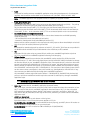
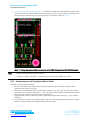
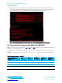
BL6xx Hardware Integration Guide Single Mode BLE Module Place regular spaced through-hole GND vias (GCPW transmission line). BL600 development board uses 0.5mm diameter through-hole GND via with 2 to 4 mm distance apart. Gap between RF_ANT trace and GND either side is 0.2 mm for below 50-Ohms impedance RF trace design. – Figure 13: BL600 development board PCB stack-up and L1 to L2 50-Ohms impedance RF trace design. 6.5 External Antenna Integration with BL600-SC and BL600-ST Please refer to the regulatory sections for FCC, IC, CE, and Japan for details of use of BL600-Sx with external antennas in each regulatory region. The BL600 family has been designed to operate with the below external antennas (with a maximum gain of 2.21 dBi). The required antenna impedance is 50 ohms. See Table 19. External antennas improve radiation efficiency. Table 19: External antennas for the BL600 External Antenna Part Number Mfg. Type Gain (dBi) Connector Type BL600 Part number EDA-8709-2G4C1-B27-CY MAG. Layers Dipole 2.0 IPEX-4 Note1 BL600-SC PCA-4606-2G4C1-A33-CY MAG. Layers PCB Dipole 2.21 IPEX-4 Note1 BL600-SC EDA-8709-2G4R2-A40-CY MAG. Layers Dipole 2.0 R-SMA Male BL600-ST Embedded Wireless Solutions Support Center: http://ews-support.lairdtech.com www.lairdtech.com/bluetooth Laird Technologies Americas: +1-800-492-2320 Europe: +44-1628-858-940 Hong Kong: +852 2923 0610