1
TN 535 WIND TURBINE
GENERAL DESCRIPTION
Date
Author
Checked
Approved
27/07/11
U. Spallinger
G. Cimatti
A. Musso
D. Spago
G. Soraperra
M. Rialti
CONFIDENTIAL.
All rights reserved.
Passing on and copying of this document, use and communication of its
content are not permitted without prior written authorization.
TN-11-47
Rel.
Pages
02
20
TN 535 GENERAL DESCRIPTION
REVISIONS
Release
Author
Date
Pages
02
M.Bonsignori
M. Rialti
29/02/2012
20
Comments
TABLE OF CONTENTS
1
INTRODUCTION ........................................................................................................... 5
1.1
PURPOSE OF THE DOCUMENT ......................................................................................................... 5
1.2
APPLICATION DOMAIN........................................................................................................................ 5
1.3
REFERENCE DOCUMENTS ................................................................................................................ 5
1.4
LIST OF ABBREVIATIONS AND DEFINITIONS................................................................................... 6
2
LIMITATIONS ................................................................................................................ 7
2.1
ENVIRONMENTAL CONDITIONS ........................................................................................................ 7
2.1.1 Cold climate ....................................................................................................................................... 8
2.1.2 Wind farm influence ........................................................................................................................... 8
2.1.3 Complex terrain ................................................................................................................................. 8
2.2
3
PROPER USE ....................................................................................................................................... 8
TECHNICAL DESCRIPTION ........................................................................................ 9
3.1
TN 535 Architecture ............................................................................................................................... 9
3.2
Electrical system overview..................................................................................................................... 9
3.3
ROTOR ................................................................................................................................................ 10
3.4
POWER TRANSMISSION ................................................................................................................... 10
3.5
GENERATOR ...................................................................................................................................... 10
3.6
YAW SYSTEM ..................................................................................................................................... 10
3.6.1 Cinematism ...................................................................................................................................... 10
3.6.2 Cable unwinding .............................................................................................................................. 10
3.7
TOWER................................................................................................................................................ 11
____________________________________________________________________________________________________________________
Company Confidential
TN 11-47
2
TN 535 GENERAL DESCRIPTION
3.8
PITCH SYSTEM .................................................................................................................................. 11
3.9
CONTROL SYSTEM ........................................................................................................................... 11
3.9.1 Yaw control ...................................................................................................................................... 11
3.9.2 Pitch control ..................................................................................................................................... 11
3.10 SAFETY SYSTEM ............................................................................................................................... 12
3.10.1
Safety relevant sensors and measurements ............................................................................... 12
3.10.2
Status signals............................................................................................................................... 12
3.10.3
Not safety relevant sensors ......................................................................................................... 13
3.11 The Brake system ................................................................................................................................ 13
3.11.1
Electrical Brake System ............................................................................................................... 13
3.11.2
Mechanical Brake System ........................................................................................................... 13
3.12
PROTECTION OF THE ELECTRICAL POWER LINE ........................................................................ 13
3.13
LIGHTENING PROTECTION .............................................................................................................. 13
4
OPERATING THE TN 535 WEC ................................................................................. 14
4.1
CONTROL LEVELS OF THE TN 535 ................................................................................................. 14
4.1.1 Level 1, access for the operator ...................................................................................................... 14
4.1.2 Level 2, access for the skilled people only ...................................................................................... 14
4.2
NORMAL OPERATING OF THE TN 535 ............................................................................................ 14
4.2.1 Idling at Low Wind Conditions ......................................................................................................... 15
4.2.2 Start up ............................................................................................................................................ 15
4.2.3 Power Production ............................................................................................................................ 15
4.2.4 Yawing ............................................................................................................................................. 15
4.2.5 Normal Shut Down because of Low Wind ....................................................................................... 15
4.2.6 High Wind Conditions ...................................................................................................................... 16
4.2.7 Shut down because of a fault condition ........................................................................................... 16
4.2.8 Manual Stop ..................................................................................................................................... 16
4.2.9 Emergency in operation ................................................................................................................... 16
4.2.10
Emergency in service .................................................................................................................. 16
APPENDIX-A: TN535 SPECIFICATIONS.......................................................................... 17
APPENDIX B: TN535 UNIFILAR SCHEMATIC ................................................................. 19
APPENDIX C: DESIGN LOAD CASE ACCORDING TO IEC 61400-2 COMING UP BY
THE DIFFERENT FAULTS ................................................................................................ 20
____________________________________________________________________________________________________________________
Company Confidential
TN 11-47
3
TN 535 GENERAL DESCRIPTION
INDEX OF PICTURES
Figure 1 - Tozzi Nord TN 535 wind turbines. ..................................................................................................... 9
Figure 2 - Operating range of the TN 535. ...................................................................................................... 14
INDEX OF TABLES
Table 1 - Reference documents. ....................................................................................................................... 5
Table 2 - List of abbreviations and definitions. .................................................................................................. 6
Table 3 Summary of environmental conditions for which TN535 is designed ................................................... 7
Table 4 Definition of important pitch angles. ................................................................................................... 11
____________________________________________________________________________________________________________________
Company Confidential
TN 11-47
4
TN 535 GENERAL DESCRIPTION
1
INTRODUCTION
1.1
PURPOSE OF THE DOCUMENT
This document provides a General Description of the TN 535 WEC.
The document is organized as follows:
•
•
•
•
1.2
Chapter 1 (the present chapter) describes the purpose of the document and its application domain;
Chapter 2 describes limitations of the TN 535 WEC;
Chapter 3 provides a short technical description of the TN 535 WEC;
Chapter 4 describes the operation of the TN 535 WEC.
APPLICATION DOMAIN
This document is applicable to TN 535 WEC designed, manufactured by Tozzi Nord.
1.3
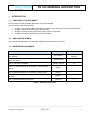
REFERENCE DOCUMENTS
TITLE
CODE
RELEASE
[Ref. 1] Wind turbines – Part 2: Design requirements for small
wind turbines
IEC 61400-2
Second edition,
2006-07
[Ref. 2] Electrical apparatus for explosive atmospheres /
Areas and zones
IEV426-03-02
-
TN535-1_MU_en
01
[Ref. 4] Electrical diagram of TN 535 WT : control & power
cabinet
60002-1
-
[Ref. 5] Electrical diagram of TN 535 WT: nacelle cabinet
60010-1
-
[Ref. 6] Electrical diagram of TN 535 WT : nacelle wiring
diagram
60021-1
-
[Ref. 7] TN 535 Lightening Protection
TN11-48
A
[Ref. 3] TN 535 User Manual
Table 1 - Reference documents.
____________________________________________________________________________________________________________________
Company Confidential
TN 11-47
5
TN 535 GENERAL DESCRIPTION
1.4
LIST OF ABBREVIATIONS AND DEFINITIONS
Abbreviation
WT
WEC
Definition
Wind Turbine
Wind Energy Converter
HW
HardWare
SW
SoftWare
PLC
Programmable Logic Controller
IEC
International Electrotechnical Commission
IEV
International Electrotechnical Vocabulary
DLC
Design Load Case
Table 2 - List of abbreviations and definitions.
____________________________________________________________________________________________________________________
Company Confidential
TN 11-47
6
TN 535 GENERAL DESCRIPTION
2
LIMITATIONS
This chapter describes the limitations to use the TN 535 WEC.
2.1
ENVIRONMENTAL CONDITIONS
TN535 is designed to withstand standard SWT-Class IV, as defined in section 6 of CEI/IEC 61400-2 [Ref. 1];
all environmental conditions for which TN535 is designed are summarized in the table below.
Wind conditions:
SWT Class
IV
Reference wind speed Vref
30.0
[m/s]
(10 min average, hub height, recurrence time 50 years)
Annual average wind speed Vave
6.0
[m/s]
turbulence intensity level at 15m/s I15
0.18
[-]
dimensionless slope parameter a
2.0
[-]
(to be used for the calculation of standard deviation turbulence as a function of Vhub and I15)
expected extreme wind speed Ve50
42.0
[m/s]
(3 sec average, hub height, recurrence time 50 years)
expected extreme wind speed Ve1
31.5
[m/s]
(averaged over 3 s, recurrence time 1 years)
design wind speed
8.4
[m/s]
Other Environmental conditions:
Normal temperature range -10<T<40 [°C]
Relative humidity of the air
<95% [-]
1.225 [kg/m3]
Air density ρ
Solar radiation
1000
[W/m2]
Lightening protection system electric scheme described in: [Ref. 4], [Ref. 5], [Ref.6]
Atmospheric content equivalent to that of a non-polluted inland atmosphere
(see IEC 60721-2-1);
Earthquake model:
TN535 standard towers and foundations are verified according to
“Decreto Ministeriale 14.01.2008,Testo Unitario - Norme Tecniche per le Costruzioni”
(NTC08), seismic class-II
Electrical network conditions:
Normal supply voltage and range 400±10% [V]
Normal supply frequency and range 50±3% [Hz]
Table 3 Summary of environmental conditions for which TN535 is designed
For sites with environmental conditions outside of the design conditions, TN cannot be held
responsible for any defects, including but not limited to damages and/or loss of energy yield.
____________________________________________________________________________________________________________________
Company Confidential
TN 11-47
7
TN 535 GENERAL DESCRIPTION
2.1.1
Cold climate
Standard machine is rated and tested for temperature range included between -10°C and +40°C. At
maximum temperature, is possible an automatic and temporary power derating, according with cycle of the
power and other environmental condition (like insulation or wind). Moving over or below these limit not
represent risk of injuries.
The product can be equipped for extended temperature range with several options: heater and or insulation,
additional ventilation, different greases. According to customer need and site characteristic right
configuration is implemented.
2.1.2
Wind farm influence
Loading of wind turbines is calculated for a single wind turbine.
In general Tozzi Nord recommend that wind turbines are placed in distances of at least 5 rotor diameters.
2.1.3
Complex terrain
Loading of wind turbines is calculated for a non-complex terrain.
Standard machine is rated for 1000m above sea level. For use over this altitude customer has to contact TN
for quantify losses in performance and eventually application limit.
2.2
PROPER USE
The machine can be used in all the conditions specifically described in the User Manual of the product
[Ref. 3], section A.5.
____________________________________________________________________________________________________________________
Company Confidential
TN 11-47
8
TN 535 GENERAL DESCRIPTION
3
TECHNICAL DESCRIPTION
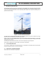
The Tozzi Nord TN 535 is a wind energy converter with a three-bladed rotor, active pitch control and variable
speed operation with a rated power of 9.9 kW. With its rotor diameter of 13.2 m and tower height of 15 or 18
or 24 m the TN 535 efficiently makes use of the prevailing wind conditions at its respective operating sites to
generate electrical energy.
Figure 1 - Tozzi Nord TN 535 wind turbines.
The main focus for development and design of all Tozzi Nord products is the idea to optimize the energy
production even at low wind speed and minimizing the loads.
Power control with variable speed allows the TN 535 to operate with optimum efficiency in the entire
operation field and avoid undesirable power spikes. Therefore guaranteeing good energy yield and high
quality power fed to the grid.
The active pitch control reduces the loads on the structure especially at high wind sppeds.
Please refers to Appendix A for further details concerning the TN 535 WEC.
3.1
TN 535 ARCHITECTURE
The TN 535 is a 3 bladed, pitch controlled wind turbine. It is designed for full variable speed, using full power
inverters for the grid connection. The rotor runs upwind.
3.2
ELECTRICAL SYSTEM OVERVIEW
Please refers to the schematics in Appendix B.
____________________________________________________________________________________________________________________
Company Confidential
TN 11-47
9
TN 535 GENERAL DESCRIPTION
3.3
ROTOR
The rotor has three blades, made out of glass reinforced epoxy resin. The blades are directly fixed to the
blade bearings which allow pitching of the blades. The TN 535 has a collective pitch, driven by an electrical
linear drive or in redundancy by a mechanical system.
3.4
POWER TRANSMISSION
The torque, produced by the rotor, is transmitted directly to the big wheel of the belt drive, without load the
main shaft with any torsion.
The belt gear has a transmission ratio of 1:11.4 and transmit the power to a PMSG (Permanent Magnet
Generator) with a nominal speed of 750 rpm .
The belt drive train adopted in the TN 535 is key point of the proposed WT. In fact, with respect to other
WT fitted with traditional gearbox train one have:
• Greater efficiency due to minor losses especially partial load.
• Minor maintenance costs (for example oil changes are no longer necessary).
• High temperature range without change in the efficiency.
• Noiseless.
• Acts as a safety friction coupling in case of the generator short circuit.
3.5
GENERATOR
The TN 535 WT adopts a PMSG with a nominal speed of 750 rpm driven by the turbine rotor by means of
the belt drive train. The generator provides its rated power already at a rotor speed of 66 rpm. The copper
windings are fitted with an isolation class F for 155 °C.
3.6
YAW SYSTEM
The Yaw system is built up by the three elements yaw bearing, yaw brake and yaw drive.
The yaw bearing is built up as a sliding bearing. This has different advantages:
• Maintenance free.
• Higher friction than a roller bearing which supports the yaw brakes.
The yaw brake is built up with two brakes loaded by compression springs. The brakes are constantly acting,
means, they brake also when the machine is yawing.
The yaw drive is an asynchronous three-phase motor 400 Vac with a flanged reduction gear. The gear is
greased for live time, means it is maintenance free. The torque of the motor is transmitted by a chain drive to
the yaw bearing. The max torque of the drive is higher than the friction torque of the brakes and the yaw
bearing
3.6.1
Cinematism
The yaw bearing is mounted directly to the top of the tower using a geared ring and a slewing ring bearing.
Two adjustment drives ("yaw drives") turn the nacelle out of the wind with the geared ring. The weight of the
nacelle is also transferred via this yaw bearing into the tower. The main carrier is attached directly to the yaw
bearing.
3.6.2
Cable unwinding
The sensors for the cable twist are switches connected to the yaw ring. Changes in the nacelle position are
converted to electric signals for the control system.
____________________________________________________________________________________________________________________
Company Confidential
TN 11-47
10
TN 535 GENERAL DESCRIPTION
3.7
TOWER
The TN 535 is sold with a 16-sides polygonal tubular steel tower, built in two sections. It is available in
heights of 14.6m, 17.6m e 23.6m.
3.8
PITCH SYSTEM
Optimum
Waiting
Parking
The TN 535 is equipped with a collective pitch system controlled by the PLC. The pitch drive consists of a
linear drive, run by a brushless DC motor. It is feed through the 28 VDC BUS of the machine. In case of grid
failure the DC BUS has a backup battery. The high speed of the pitch drive allows the blade angle to be
quickly and precisely adjusted according to the prevailing wind conditions.
Actual TN535 setup consider an optimum root-pitch of +13.3°, a waiting root-pitch of 36.3° and a parki ng
root-pitch of 87.4°.
Nominal-pitch →
2.0
25.0
76.1
[deg]
Tip-pitch →
0.5
23.5
74.6
[deg]
root-pitch at r=1500mm
→
(reference for this document)
13.3
36.3
87.4
[deg]
Table 4 Definition of important pitch angles.
3.9
CONTROL SYSTEM
The TN 535 control system is based on an industrial PLC which constantly monitors the sensors of the
various components as well as e.g. the data of wind direction and wind speed and in return adapts the
operation of the TN 535 accordingly.
This is done by optimizing the rotor speed, the blade angle, the yaw position of the nacelle and the power
output of the generator accordingly.
During operation, all relevant sensors are constantly monitored in order to initiate the appropriate measures
(e.g. parking or emergency stop) in case an irregularity occur.
3.9.1
Yaw control
The wind vane at hub height continuously detects the wind direction. If the average deviation of the
nacelle direction compared to the measured wind direction is greater than a certain quantity, the nacelle
is repositioned by means of the yaw motor. Yaw motion is monitored by counting the rotations of the yaw
motor and by checking the yaw time for plausibility.
3.9.2
Pitch control
When the maximum rotor speed limit is reached, the blade angles are changed accordingly to keep it
constant. To achieve this, the appropriate blade angle is selected by evaluating the speed and acceleration
measurements.
____________________________________________________________________________________________________________________
Company Confidential
TN 11-47
11
TN 535 GENERAL DESCRIPTION
3.10 SAFETY SYSTEM
The safety system of the TN 535 is designed to keep the wind turbine under safe condition in all cases
mentioned in the norm IEC 61400-2 [Ref. 1]. To control the machine and guaranty its safety, the values are
monitored continuously by the PLC.
Appendix C shows the load case according to IEC 61400-2 [Ref. 1] coming up by the different faults.
There are three types of sensors or status monitored:
• Safety relevant sensors.
• Status signals from switches and inverters.
• Not safety relevant sensors.
3.10.1 Safety relevant sensors and measurements
The safety relevant sensors are continuously checked for reliable values. These sensors stop the machine in
a normal braking procedure by pitching the blades into braking position whenever the value is out of the
threshold or not reliable.
• Rotor speed sensors 1, checked continuously by comparing with rotor sensor 2.
• Rotor speed sensors 2, checked continuously by comparing with rotor sensor 1.
• Vibration sensor, checked continuously for unreliable values cause by short circuit or broken
cable.
• Voltage level of 28 VDC checked continuously.
• Battery voltage level, checked monthly and after each start up out of the braking position.
• Battery capacity, checked monthly and after each start up out of the braking position.
• Belt slipping, checked continuously by comparing rotor speed and generator speed.
• Yaw sensor 1, checked when passing the maker, right sequence with yaw sensor 2.
• Yaw sensor 2, checked when passing the maker, right sequence with yaw sensor 1.
• Yaw time, checked by a timer.
• Sensor pitch drive braking position, checked when moving to braking position by a timer.
• Sensor pitch drive waiting position, checked when moving to waiting position by a timer.
• Sensor pitch drive working position, checked when moving to working position by a timer.
3.10.2 Status signals
If a status signal is missing or the value is wrong, the machine is stopped in a normal braking procedure by
pitching the blades into braking position.
• Inverter status, checked continuously.
• Status of 28 VDC grid supply switch, checked continuously.
• Status of 28 VDC sensors switch, checked continuously.
• Grid failure, checked continuously.
• Grid monitoring interface, checked continuously.
• Yaw motor protection, checked continuously.
____________________________________________________________________________________________________________________
Company Confidential
TN 11-47
12
TN 535 GENERAL DESCRIPTION
3.10.3 Not safety relevant sensors
Not safety relevant sensors cause a warnings.
Hereafter a list of not relevant sensors:
• Wind vane broken or iced, checked continuously
• Generator temperature, checked continuously for unreliable values cause by short circuit or
broken cable.
3.11 THE BRAKE SYSTEM
The TN 535 brakes always aerodynamically by collective pitching the three blades. There are two
independent actuator systems working on the pitch mechanism of the three blades. The main actuator is
electrically driven, the emergency actuator is a completely independent mechanical system.
3.11.1 Electrical Brake System
The electrical system uses an electrical linear actuator working on all three blades by a mechanical system.
The electric power is coming from the 28 VDC BUS, feed by a power supply, feed from the grid. A backup
battery is always kept charged and its capacity is tested monthly by the controller.
3.11.2 Mechanical Brake System
The mechanical emergency system is triggered by centrifugal force when the electrical system is not working
anymore and the machine goes into an rotor over speed. The energy to move the pitch system is coming
from the rotating rotor. The system is designed to have ten times the power of the electrical system. The high
power of the emergency system gives the assurance, that it is able pitch the blades into the braking position,
even then the electrical actuator was not able any more. The emergency system has to be rested by hand,
means a skilled person has to climb the nacelle.
3.12 PROTECTION OF THE ELECTRICAL POWER LINE
The electric power line is mainly protected by the control logic of the static converter against following faults:
• Generator short circuit to ground
• Generator short circuit phase to phase
• Short circuit in the cables between generator and inverter
• Inverter faults
• Grid failure
3.13 LIGHTENING PROTECTION
Please refers to TN 535 Lightening Protection document [Ref. 7] .
____________________________________________________________________________________________________________________
Company Confidential
TN 11-47
13
TN 535 GENERAL DESCRIPTION
4
OPERATING THE TN 535 WEC
This paragraph describes the main operating conditions of the TN 535 WEC. For a more detailed
information, please refers to the User Manual [Ref. 3].
4.1
CONTROL LEVELS OF THE TN 535
4.1.1
Level 1, access for the user
The user, usually the customer of the machine, is the person who has read and understood the instructions
of use expressed in the User Manual Wind turbine model TN535 [Ref 3].He has access to the first level. On
this level is an OPERATION MODE SELECTOR SWITCH and the MAIN SWITCH.
The OPERATION MODE SELECTOR SWITCH has three positions:
1. OFF
2. Standby
3. Auto
The WEC is completely off, it does not pitch nor yaw.
The WEC is off, it does not pitch but still align to the wind.
The WEC is in automatic operation, normal position of the switch. The behaviour of
the WEC is descript in next paragraphs.
Any time, the switch is moved out of the position Auto, the turbine goes into braking position by pitching the
blades.
Furthermore the MAIN SWITCH cuts off the electricity coming from the grid to the WEC and the opposite’s
way.
4.1.2
Level 2, access for the skilled people only
This level is used only for service and outstands from the purpose of the present document.
4.2
NORMAL OPERATING OF THE TN 535
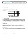
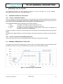
The figure below shows the operating range of the TN 535. The controller keeps the machine always inside
the allowed envelope. All start up and brake down procedures are performed automatically.
Figure 2 - Operating range of the TN 535.
____________________________________________________________________________________________________________________
Company Confidential
TN 11-47
14
TN 535 GENERAL DESCRIPTION
4.2.1
Idling at Low Wind Conditions
If the wind is not strong enough for energy production, the turbine switches into the status waiting, pitching
the blades to an angle of approximately 36.3° and s witch off the inverters. The rotor is then idling with about
rpm
2.5 /m/s over m/s of wind speed. The yaw system is aligning the nacelle to the wind whenever necessary.
4.2.2
Start up
If the average rotary speed in the waiting position exceeds during 100 seconds 11 rpm, or if the present
rotary speed in the waiting position exceeds 20 rpm, the turbine switches from status waiting to the status
start up. The status start up has the following sequences:
• Start up the inverters.
• Accelerated the rotor speed along a ramp up to 20 rpm by pitching the blades.
• Wait at 20 rpm for the acknowledgment of the inverters.
• If the ok of the inverters does not arrive within 10 s, the machine goes into and inverter fault
condition and tries after 2 minutes again. This is done 5 times before a fault condition is signalled to
the maintainer.
• If the ok of the inverters arrives within 10 s, the status is switched to power production , the inverters
are activated and the rotor speed is accelerated along a ramp by pitching the blades to the optimal
pitch position of 2°.
4.2.3
Power Production
There are two different situations in the power production of the turbine:
• Below rated wind speed.
• Above rated wind speed.
Below the rated wind speed, the machine is working in the optimal pitch angle. The rotor speed is controlled
by the generator torque to let the blades work in the point of maximum efficiency, means the rotor speed is
rd
almost linear to the wind speed. The power production grows more or less with the 3 power of the wind
speed.
Above the nominal wind speed, the turbine controls the rotor speed by pitching the blades, try to keep the
nominal rotor speed. Because the turbine is connected by an inverter to the grid, the system is “soft” and the
rotor speed can vary a little bit around the nominal rotor speed. In the last, the power is all the time at
nominal power.
4.2.4
Yawing
The TN 535 has an active yaw system. A wind vane measures the relative wind direction according to the
WEC and an special algorithm controls the yaw drive in a way, that it does not move to often but keeps the
WEC aligned to the prevalent wind direction.
In case of a broken wind vane or one of its cables, the PLC doesn’t yaw anymore and gives out the warning
“wind vane broken”.
In case of blowing wind and the signal of the wind vane is not changing for a certain period, the PLC doesn’t
yaw anymore and gives out the warning “wind vane not moving”.
4.2.5
Normal Shut Down because of Low Wind
When, in the status Power , the rotary speed drops below 25 rpm in the average over 30 seconds or when it
drops below 8 rpm, the system returns to the status waiting by pitching the blades to 36.3°.
____________________________________________________________________________________________________________________
Company Confidential
TN 11-47
15
TN 535 GENERAL DESCRIPTION
4.2.6
High Wind Conditions
In the event of wind speeds over 16 m/s (average over 480 sec), or maximum gusts over 22 m/s, the turbine
stops down by pitching the blades to the parking position (87.4° pitch angle). The PLC decides when th e
wind has fallen sufficiently for a return to the production state.
4.2.7
Shut down because of a fault condition
Most of the faults causes a normal shut down of the machine, means, the rotor is stopped by pitching the
rpm
blades into the parking position of about 87.4°. In this position, the machine is idling with about 0.6
/m/s.
The yaw is still aligning the nacelle to the wind whenever necessary.
4.2.8
Manual Stop
The TN 535 can be stopped manually by switching the OPERATION MODE SELECTOR SWITCH out of the
position Auto. The turbine goes into parking position by pitching the blades.
4.2.9
Emergency in operation
If any anomalous condition is detected the machine can be switched off through the OPERATION MODE
SELECTOR SWITCH.
In case of fire the machine should also be switched be switched off from the external main through the MAIN
SWITCH.
4.2.10 Emergency in service
During service operation all the actuator and the voltage in nacelle can be switched off pressing one of the
EMERGENCY BUTTON (one in nacelle and one inside the control cabinet).
____________________________________________________________________________________________________________________
Company Confidential
TN 11-47
16
TN 535 GENERAL DESCRIPTION
APPENDIX-A: TN535 SPECIFICATIONS
Turbine Architecture:
Type:
Direction of rotation:
Number of blades:
Rotor diameter:
Hub height:
Nominal electric power:
Power regulation:
Cut-in wind speed
Cut-out wind speed
Nominal output at
Rotor diameter
Swept area:
Upwind rotor with active pitch control and active yaw
control
Clockwise, seen from upwind
3
13.2 m
15 -18 -24m
9,9 kW
Active pitch (pitch to feather)
2.5 m/s
16 m/s
6.7 m/s
13.2 m
136.7 m2
Rotor
Type
Blade length
Material
Lightening protection
Hub:
LWTB535
6.344 m
GFRP
Optional
Rigid (no tilt)
Drive train
Transmission
Main bearing:
High speed shaft rotational speed
belt drive
Single-row ball bearing
225-750 rpm
Low speed shaft rotational speed
Grid feed:
20-66 rpm
ABB ACS M1
Generator
Nominal power
Type
Protection
Insulation class
11.0 kVA
Permanent Magnets Synchronous Generator 8 poles
IP54
F
____________________________________________________________________________________________________________________
Company Confidential
TN 11-47
17
TN 535 GENERAL DESCRIPTION
Yaw System
Yaw Type
Active yaw control,
1 driver, 2 beaks (always braking)
Yaw Rate
3.35 deg/s
Controller
Type
Remote monitoring
UPS
PLC
Tozzi Nord SCADA / Real Time Viewer
Backup by means fo lead acid batteries (2X12V)
Breaking System
Aerodynamic brake
Collective pitch
Redundant aerodynamic brake
Rotor lock
Passive centrifugal system that bring blades to barking
position
Metal pin inserted for maintenance
Tower
tower height
tower type
Design wind class
14.6m-17.6 m - 23.6 m
polygonal steel tower, 16 sides, 2 sections
IV
Weights
Nacelle, excluding rotor and hub
rotor, including hub
Tower
783 kg
332 kg
1300kg (14.6m)-1750kg (17.6m)-3350kg (23.6m)
Noise emissions
Max Lwa@10m/s
87.1dB
____________________________________________________________________________________________________________________
Company Confidential
TN 11-47
18
TN 535 GENERAL DESCRIPTION
APPENDIX B: TN535 UNIFILAR SCHEMATIC
____________________________________________________________________________________________________________________________________________________________________________
Company Confidential
TN 11-47
19
TN 535 GENERAL DESCRIPTION
APPENDIX C: DESIGN LOAD CASE ACCORDING TO IEC 61400-2 COMING UP BY THE DIFFERENT FAULTS
____________________________________________________________________________________________________________________________________________________________________________
Company Confidential
TN 11-47
20