1
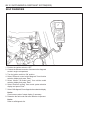
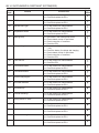
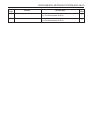
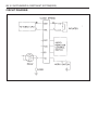
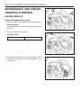
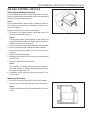
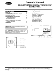
SECTION 8B
SUPPLEMENTAL RESTRAINT SYSTEM(SRS)
Caution: Disconnect the negative battery cable before removing or installing any electrical unit or when a
tool or equipment could easily come in contact with exposed electrical terminals. Disconnecting this cable
will help prevent personal injury and damage to the vehicle. The ignition must also be in LOCK unless otherwise
noted.
TABLE OF CONTENTS
Specifications. . . . . . . . . . . . . . . . . . . . . . . . 8B-1
General Specifications . . . . . . . . . . . . . . . . . . 8B-1
Schematic and Routing Diagrams . . . . . . . . 8B-2
Air Bag . . . . . . . . . . . . . . . . . . . . . . . . . . . . . . 8B-2
Cautions . . . . . . . . . . . . . . . . . . . . . . . . . . . . 8B-3
Function Description . . . . . . . . . . . . . . . . . . 8B-4
Air Bag Module . . . . . . . . . . . . . . . . . . . . . . . . 8B-6
Diagnosis . . . . . . . . . . . . . . . . . . . . . . . . . . . 8B-7
Description . . . . . . . . . . . . . . . . . . . . . . . . . . . 8B-7
Self Diagnosis . . . . . . . . . . . . . . . . . . . . . . . . 8B-10
Circuit Diagram . . . . . . . . . . . . . . . . . . . . . . . 8B-16
Air Bag Diagram . . . . . . . . . . . . . . . . . . . . . . 8B-17
Maintenance and Repair . . . . . . . . . . . . . . 8B-18
On-Vehicle Service . . . . . . . . . . . . . . . . . . . . .
Air Bag Module . . . . . . . . . . . . . . . . . . . . . . .
Clock Spring . . . . . . . . . . . . . . . . . . . . . . . . .
Air Bag Control Unit (AC4) . . . . . . . . . . . . . .
General Description and System
Operation . . . . . . . . . . . . . . . . . . . . . . . .
Introduction . . . . . . . . . . . . . . . . . . . . . . . . . .
Caution . . . . . . . . . . . . . . . . . . . . . . . . . . . . .
8B-18
8B-18
8B-19
8B-21
8B-22
8B-22
8B-22
SPECIFICATIONS
GENERAL SPECIFICATIONS
Application
Air bag System Deployment Time
Detection Time
Operating Temperature
Storage Temperature
Air Bag Replacement Interval
Voltage Range
Current Consumption
Acceleration Range
Max. Acceleration
Voltage Ramp
Energy Reservation
Inflator Ignition Energy
Squib Resistance
Air Bag Warning Lamp ON Time (When Ignition ON)
Description
< 20ms
< 5ms
-40°C ~ +85°C
-40°C ~ +90°C
Every 10-year after installation
9-16V
5ms after ignition switch ON < 1A,
5ms ~ 5sec. <300mA, after 5sec. < 100mA
+/-50g
+/-600g pulse
0.5 ~ 2.0 V/s
150ms after battery disconnection
4.3mJ
2.15 ± 0.35 Ω
6 sec.
8B-2 SUPPLEMENTAL RESTRAINT SYSTEM(SRS)
AIR BAG
SCHEMATIC AND ROUTING DIAGRAMS
SUPPLEMENTAL RESTRAINT SYSTEM(SRS) 8B-3
CAUTIONS
Failure to follow the correct service procedure can cause air bag damage or personal injury due to unexpected air
bag deployment. Before service (removal and installation of part, check for replacement), please be weal noticed of
following items for your correct service.
1. For service, turn the ignition switch to ‘LOCK’ position and wait for 30 seconds after disconnecting the negative
battery cable.
2. If the vehicle collapsed, remove the air bag ECU first to reserve the crash records.
3, Never use other vehicles’ air bag components and replace with specified new part.
4. Never disassemble or repair the air bag module, air bag unit and wiring harness to re-use.
5. Replace the air bag module and air bag unit with new if it dropped, cracked or damaged.
6. Only qualified technicians in service shop should check or repair the air bag,
7. Before service, should be well noticed of warning labels on the vehicle.
A. Sun Visor Side
D. Engine Compartment
[Warning]
Pull down the sun visor and see SRS air bag
warning lamp on the head lining.
[Warning]
This vehicle is equipped with air bag. Before
checking the engine compartment, read service
manual first. Faultuy check and service can cause
SRS air bag deployment and system defects that
can be led to severe damage.
B. Head Lining
[Warning]
1 . This vehicle is equipped with air bag. Air bag is
supplemental device for the seatbelt. Fasten
your seatbelt.
2. This air bag should be replaced by authorized
supplier within replacement intervals.
3. When the ignition key is turned to ON position,
SRS warning lamp will turn on for 6 sec. and go
off. In this case, the system is normal.
For the following cases, see service manual.
- SRS warning lamp does not turn on.
- SRS warning lamp does not go off.
- SRS warning lamp continues to blink.
C. Steering Wheel Body Inner
[Warning]
Before removing the steering wheel, read service
manual first. Set the front wheels straight forward
and align the center position marks of SRS clock
spring. Improper removal or installation of the
steering wheel can damage the SRS components.
E. Battery Cable
[Warning]
Before disconnecting the battery power, read
service manual first.
8B-4 SUPPLEMENTAL RESTRAINT SYSTEM(SRS)
FUNCTION DESCRIPTION
Air Bag Control Unit (AC4)
Air bag control unit (AC4) is installed on the center portion of
the front floor tunnel.
It is a central control unit that control all functions and determines
whether deploy the air bag or not with the collision signal from
the built-in accelerometer sensor and has function of diagnosing
system defects.
Internal air bag control unit is consisted as follows;
l Microprocessor
l ASICs (Upper side ASIC & lower side ASIC)
l Accelerometer sensor
l Arming sensor
l System energy backup condenser
l Squib energy backup condenser
SUPPLEMENTAL RESTRAINT SYSTEM(SRS) 8B-5
Input & Output Function
Electronic air bag control and diagnosis module is connected
by full 30-pin connectors.
Input : ground
Output : 1 squib line, warning lamp
Input/output : communication, diagnosis
5
+
IGN
2
GND
Air bag
control
unit
Ground connection or open
1
-
Air bag lamp
Warning lamp
20
Communication/
diagnosis
RxD/TxD
13
Inflator line 1
14
Connector Pins
15
1
30
16
1
2
3
4
5
6
7
8
9
10
11
12
13
14
15
Lamp
Ground
N/A
N/A
Ignition
N/A
N/A
CONF
N/A
N/A
N/A
N/A
Squib Line 1(upper)
Squib Line 1(lower)
N/A
16
17
18
19
20
21
22
23
24
25
26
27
28
29
30
Shorting Bar
Shorting Bar
Shorting Bar
Shorting Bar
Diagnosis
Shorting Bar
Shorting Bar
No Pin
No Pin
Shorting Bar
Shorting Bar
N/A
Shorting Bar
Shorting Bar
N/A
8B-6 SUPPLEMENTAL RESTRAINT SYSTEM(SRS)
AIR BAG MODULE
Air bag module is installed in the pad of steering wheel center and inflator is consisted of igniter, explosives, gas
generating material and bag. When crashed, the air bag control unit sends current to the air bag module through
squib line and this current ignites as ignition energy (6mJ) momentarily igniting explosives and bag will be inflated
by nitrogen gas protecting driver at the same and then deflates.
1
2
3
4
Air bag Module
Module Housing
Bag
Module Bracket
5
6
7
8
Retainer Ring
Inflator
Horn Switch
Backing Plate
SUPPLEMENTAL RESTRAINT SYSTEM(SRS) 8B-7
DIAGNOSIS
DESCRIPTION
Air bag control unit continuously controls system function as follows during ignition ON or driving.
- Recognition of collision
- Internal diagnosis
- External diagnosis
If recognize or detect defects, warning lamp will turn on. If there is danger of improper deployment, the system will
enter overall shutdown status and the air bag will not inflate.
Air bag control unit will store detected internal and external defects in the EEPROM.
System Control
Battery Voltage Check
Battery voltage will be monitored continuously. If voltage is out of normal operating range, all system diagnosis will
stop and warning lamp turn on.
Battery Voltage (V)
< 8.7
9 - 16
> 16.3
Function
System diagnosis stops and warning lamp turns on
Normal operation range
System diagnosis stops and warning lamp turns on
Squib Diagnosis
It checks not only high (4.50.5) or low (1.40.5) resistance but also short resistance (1- 10k) status between the
battery and ground to indicate defects in squib line by blinking warning lamp. Air bag control unit (AC4) can measure
squib resistance.
Warning Lamp Turning On
Air bag control unit detects system defects during ignition ON or driving and displays following 2 warning lamps.
- Warning lamp ON: internal defects of the air bag control unit
- Warning lamp blinking: higher resistance than standard in the squib line or short at the battery or ground,
Safety Function Check
It checks defects during operation of the arming sensor If the sensor is shorted for more than 2 seconds, the module
will enter overall shutdown mode.
Temperature Sensor
Function of the temperature sensor will be monitored continuously. If there is fault due to defective sensor or short,
the lamp will turn on and program will take calibration temperature (25) of collision conditions.
Power Supply
Airbag control unit operates in 9-16v and the characteristic of the system has backup condenser to supply the power
for max.150ms if there is power defect during collision.
8B-8 SUPPLEMENTAL RESTRAINT SYSTEM(SRS)
Energy Reserve System
Energy reserve system is consisted of condensor and energy switch and will check following items continuously
during system operation.
- High voltage
- Low voltage
- Low rating capacity
- Function of the energy reserve switch
If there is fault in the energy reserve system, warning lamp will turn on. And defects are found by continuous
checking of the condenser voltage, the system will enter overall shutdown status for safety reason.
Shutdown Switch
There is 1 energy shutdown switch in the system and it will be checked during start-up. And it also checks that
condenser is discharging properly. If shutdown switch is short, it will be detected during condensor voltage test.
If squib line fault is obvious, the warning lamp will turn on and the module will enter overall shutdown status.
Accelerometer Check
Accelerometer function will be checked during start-up. During operation, accelerometer off-set signal will be checked,
If there is fault, module will enter overall shutdown status.
ASIC Overheat
Module monitors upper side ASIC overheats continuously. If overheated, the module will enter overall shutdown
status.
Microprocessor Fault
Module checks EEPROM, ROM checksum and RAM during start-up. EEPROM tests checksum operation.
If RAM or ROM checksum is defective, module will not allow start-up continuously but will be re-set,
If EEPROM is defective, warning lamp will turn on and the module will enter overall shutdown status.
During operation, RAM will continuously verify the proper operation of temporary memory program data usage. If
there is fault, the module will enter overall shutdown status and the warning lamp will turn on.
Watchdog Test
Watchdog function will be tested in start-up. If there is fault during the test, warning lamp will turn on and the module
will enter overall shutdown status.
SUPPLEMENTAL RESTRAINT SYSTEM(SRS) 8B-9
Diagnosis
Air bag control unit diagnoses each function in the intervals of 250ms - 20 sec. during start-up or driving to prevent
unwanted air bag deployment. If there is defect, it turns on or blinks warning lamp to indicate defects in the air bag
system to the driver. And fatal defect is found, air bag control unit enters overall or partial shutdown status and fault
code will be stored.
Air bag control unit diagnoses following items.
Diagnosis Condition
Diagnosis Items
Start-up (ignition ON)
- Ignition TR
- Acceleration
- Microprocessor, RAM and ROM
- Watchdog
- Shutdown Switch
During Driving
- Squib resistance
- Squib line short to battery and ground
- Energy reserve system
- Lamp output
- Battery voltage
- ASIC communication
- Arming sensor
- ASIC overheating
- RAM and W/D
- EEPROM
Lamp Blinking Mode
There are 2 kinds of blinking mode
1. When system internal fault is found, the lamp will stay on.
2. The lamp will blink according to external fault and there are 2 blinking codes.
Blinking code 1 (Squib resistance fault in the driver’ s air bag squib line)
Blinking code 2 (Squib short on plus and minus in the air bag squib line)
Lamp blinking code is as follows. The last blinking will be within 0.5 sec. and 1 cycle of blinking will be repeated every
5 seconds.
Blinking Code 1
(Sec.) 0
0.5
1
1.5
2
2.5
3
3.5
4
4.5
1
1.5
2
2.5
3
3.5
4
4.5
Blinking Code 3
(Sec.) 0
0.5
8B-10 SUPPLEMENTAL RESTRAINT SYSTEM(SRS)
SELF DIAGNOSIS
1. Position the ignition switch to ‘OFF’.
2. Connect the harness connector of scanner to the diagnosis
socket in engine compartment.
3. Turn the ignition switch to ‘ON’ position.
4. Select “Electronic control vehicle diagnosis” from function
selection display and press ‘Enter’ .
5. Select “Musso (’98 model year)” from vehicle model
selection display and press ‘Enter’ .
6. Select “Electronic air bag” from control system selection
display and press ‘Enter’ .
7. Select “Self-diagnosis” from diagnosis item selection display.
Notice
Check sensor value of output display, if necessary.
8. Determine the fault code and trace defective component.
Notice
Refer to self-diagnosis list.
SUPPLEMENTAL RESTRAINT SYSTEM(SRS) 8B-11
Self-Diagnosis List
Fault
Code
Defects
Service Hint
Application
01
Driver’ s squib (+) side No. 1
l Short of (+) side No. 1 in the driver’ s squib circuit.
l Check connection of connector.
l Check the ECU.
02
Driver’ s squib (+) side No. 2
l Short of (+) side No. 2 in the driver’ s squib circuit.
l Check connection of connector.
l Check the ECU.
X
03
Driver’ s squib (+) side No. 3
l Short of (+) side No. 3 in the driver’ s squib circuit.
l Check connection of connector.
l Check the ECU.
X
04
Driver’ s squib (+) side No. 4
l Short of (+) side No. 4 in the driver’ s squib circuit.
l Check connection of connector.
l Check the ECU.
X
05
Driver’ s squib ground (-) side No. 1
l Short of ground side No. 1 in the driver’ s squib
circuit.
l Check and replace the ECU.
06
Driver’ s squib ground (-) side No. 2
l Short of ground side No. 2 in the driver’ s squib
X
circuit.
l Check and replace the ECU.
07
Driver’ s squib ground (-) side No. 3
l Short of ground side No. 3 in the driver’ s squib
X
circuit.
l Check and replace the ECU.
08
Driver’ s squib ground (-) side No. 4
l Short of ground side No. 4 in the driver’ s squib
X
circuit.
l Check and replace the ECU.
09
Energy shutdown switch No. 1
l Air bag control unit internal defects.
l Check and replace the ECU.
10
Energy shutdown switch No. 2
l Air bag control unit internal defects.
l Check and replace the ECU.
X
11
Energy shutdown switch No. 3
l Air bag control unit internal defects.
l Check and replace the ECU.
X
12
Energy shutdown switch No. 4
l Air bag control unit internal defects.
l Check and replace the ECU.
X
13
Ignition switch wire No. 1
l Air bag control unit internal defects.
l Check and replace the ECU.
14
Ignition switch wire No. 2
l Air bag control unit internal defects.
l Check and replace the ECU.
X
15
Ignition switch wire No. 3
l Air bag control unit internal defects.
l Check and replace the ECU.
X
16
Ignition switch wire No. 4
l Air bag control unit internal defects.
l Check and replace the ECU.
X
8B-12 SUPPLEMENTAL RESTRAINT SYSTEM(SRS)
Fault
Code
17
Defects
Squib No. 1 resistance
Service Hint
l Driver’ s squib resistance is higher than standard
l
l
l
l
l
18
Squib No. 2 resistance
Squib No. 3 resistance
Squib No. 4 resistance
21
Squib No. 1 resistance
Squib No. 2 resistance
Squib No. 3 resistance
(1.4±0.3W).
Check related circuits for open/short.
Check connection of connector.
Check the ECU.
Replace the squib wire.
Plus side short : 7k, ground side short : 6kW.
l Driver’ s squib resistance is lower than standard
l
l
l
l
l
23
X
(4.5±0.5W).
Check related circuits for open/short.
Check connection of connector.
Check the ECU.
Replace the squib wire.
Plus side short : 7k, ground side short : 6kW.
l Driver’ s squib resistance is lower than standard
l
l
l
l
l
22
X
(4.5±0.5W).
Check related circuits for open/short.
Check connection of connector.
Check the ECU.
Replace the squib wire.
Plus side short : 7k, ground side short : 6kW.
l Driver’ s squib resistance is higher than standard
l
l
l
l
l
X
(4.5±0.5W).
Check related circuits for open/short.
Check connection of connector.
Check the ECU.
Replace the squib wire.
Plus side short : 7k, ground side short : 6kW.
l Driver’ s squib resistance is higher than standard
l
l
l
l
l
20
(4.5±0.5W).
Check related circuits for open/short.
Check connection of connector.
Check the ECU.
Replace the squib wire.
Plus side short : 7k, ground side short : 6kW.
l Driver’ s squib resistance is higher than standard
l
l
l
l
l
19
Application
l Driver’ s squib resistance is lower than standard
l
l
l
l
l
X
(1.4±0.3W).
Check related circuits for open/short.
Check connection of connector.
Check the ECU.
Replace the squib wire.
Plus side short : 7k, ground side short : 6kW.
(1.4±0.3W).
Check related circuits for open/short.
Check connection of connector.
Check the ECU.
Replace the squib wire.
Plus side short : 7k, ground side short : 6kW.
X
SUPPLEMENTAL RESTRAINT SYSTEM(SRS) 8B-13
Fault
Code
24
Service Hint
Application
l Driver’ s squib resistance is lower than standard
X
Defects
Squib No. 4 resistance
l
l
l
l
l
(1.4±0.3W).
Check related circuits for open/short.
Check connection of connector.
Check the ECU.
Replace the squib wire.
Plus side short : 7k, ground side short : 6kW.
25
Energy reserve No. 1 voltage
l Air bag control unit internal defects.
l Check and replace the ECU.
26
Energy reserve No. 2 voltage
l Air bag control unit internal defects.
l Check and replace the ECU.
X
27
Energy reserve No. 3 voltage
l Air bag control unit internal defects.
l Check and replace the ECU.
X
28
Energy reserve No. 4 voltage
l Air bag control unit internal defects.
l Check and replace the ECU.
X
29
Energy reserve No. 5 voltage
l Air bag control unit internal defects.
l Check and replace the ECU.
30
Energy reserve No. 6 voltage
l Air bag control unit internal defects.
l Check and replace the ECU.
31
Energy reserve No. 1 current off
capacity
l Air bag control unit internal defects.
l Check and replace the ECU.
32
Energy reserve No. 2 current off
capacity
l Air bag control unit internal defects.
l Check and replace the ECU.
X
33
Energy reserve No. 3 current off
capacity
l Air bag control unit internal defects.
l Check and replace the ECU.
X
34
Energy reserve No. 4 current off
capacity
l Air bag control unit internal defects.
l Check and replace the ECU.
X
35
Energy reserve No. 5 current off
capacity
l Air bag control unit internal defects.
l Check and replace the ECU.
36
Condensor voltage
l Air bag control unit internal defects.
l Check and replace the ECU.
37
Collision times checksum
l Air bag control unit internal defects.
l Check and replace the ECU.
38
Driver’ s acceleration sensor
l Air bag control unit internal defects.
l Check and replace the ECU.
39
Driver’ s acceleration sensor off-set
l Air bag control unit internal defects.
l Check and replace the ECU.
40
Arming sensor
l Air bag control unit internal defects.
l Check and replace the ECU.
41
Major USA
l Air bag control unit internal defects.
l Check and replace the ECU.
8B-14 SUPPLEMENTAL RESTRAINT SYSTEM(SRS)
Fault
Code
Service Hint
Defects
42
Over heat
l Air bag control unit internal defects.
l Check and replace the ECU.
43
SENS
l Air bag control unit internal defects.
l Check and replace the ECU.
44
Standard band gap
l Air bag control unit internal defects.
l Check and replace the ECU.
45
Temperature sensor
l Air bag control unit internal defects.
l Check and replace the ECU.
46
Warning lamp
l
l
l
l
47
Battery voltage
l Power wire voltage is out of standard voltage (9
l
l
l
l
Open/short in the warning lamp circuit.
Check related circuits for open/short.
Check connection of connector.
Check the ECU.
- 16V).
Check the battery for voltage and charging.
Check related circuits for open/short.
Check connection of connector.
Check the ECU.
49
Fault code list
l Air bag control unit internal defects.
l Check the ECU.
50
USA communication
l Air bag control unit internal defects.
l Check and replace the ECU.
51
LSA communication
l Air bag control unit internal defects.
l Check and replace the ECU.
52
No EEPROM program
l Air bag control unit internal defects.
l Check and replace the ECU.
53
EEPROM checksum
l Air bag control unit internal defects.
l Check and replace the ECU.
54
EEPROM map
l Air bag control unit internal defects.
l Check and replace the ECU.
55
External watchdog 1
l Air bag control unit internal defects.
l Check and replace the ECU.
56
Arming sensor-no close
l Air bag control unit internal defects.
l Check and replace the ECU.
57
RAM check
l Air bag control unit internal defects.
l Check and replace the ECU.
58
System
l Air bag control unit internal defects.
l Check and replace the ECU.
59
External watchdog 2
l Air bag control unit internal defects.
l Check and replace the ECU.
60
Pulse
l Air bag control unit internal defects.
l Check and replace the ECU.
Application
SUPPLEMENTAL RESTRAINT SYSTEM(SRS) 8B-15
Fault
Code
Defects
Service Hint
127
Collision signal
l Air bag control unit internal defects.
l Check and replace the ECU.
128
Collision number
l Air bag control unit internal defects.
l Check and replace the ECU.
Application
8B-16 SUPPLEMENTAL RESTRAINT SYSTEM(SRS)
CIRCUIT DIAGRAM
SUPPLEMENTAL RESTRAINT SYSTEM(SRS) 8B-17
AIR BAG DIAGRAM
8B-18 SUPPLEMENTAL RESTRAINT SYSTEM(SRS)
MAINTENANCE AND REPAIR
ON-VEHICLE SERVICE
AIR BAG MODULE
Removal & Installation Procedure
1. Remove the steering wheel rid (LH,RH) with a screwdriver.
Installation Notice
Each position mark (LH,RH) is stamped on the inner surface
of the rids.
2. Unscrew the bolts from both sides.
Installation Notice
Tightening Torque
7 - 11 Nm
3. Disconnect the connectors and remove the air bag module.
4. Installation should follow the removal procedure in the
reverse order.
SUPPLEMENTAL RESTRAINT SYSTEM(SRS) 8B-19
CLOCK SPRING
General Specification
Voltage
Rating Operating Voltage
Current Rating
Air Bag
Horn (Relay)
Remote Control (Electronic Circuit)
Air Bag Circuit Resistance
Isolating Resistance
Rotating Range
Notice
l Clock spring can not be repaired.
l Do not disassemble or modify.
l To adjust to the center position, rotate clockwise until it
stops and then rotate it counterclockwise 2.3 ± 0.2
revolutions and align marks. If not, airbag system can
not work normally and driver can be injured seriously.
DC 12V
DC 6 - 18V
10 - 30mA(6A,0.1second)
200 - 220mA
15mA
0.16 - 0.38Ω(-40°C - 85°C)
5MΩ
2.7 - 3.1 Rotation from neutral
Position to Both Sides
8B-20 SUPPLEMENTAL RESTRAINT SYSTEM(SRS)
Removal & Installation Procedure
preceding work : removal of steering wheel
1. Turn the ignition switch to “OFF” position and disconnect
the battery negative cable. Start the procedure after waiting
over 3oseconds.
2. Unscrew 3 screws from lower cover on steering column shaft
and remove the lower cover.
3. Unscrew 4 screws from clock spring and remove the clock
spring
Installation Notice
l Don’t try to repair and modify the clock spring.
l When aligning the neutral position, turn to clockwise until it
stops, and turn to counter clockwise until the marks are
aligned
SUPPLEMENTAL RESTRAINT SYSTEM(SRS) 8B-21
AIR BAG CONTROL UNIT(AC4)
Removal & Installation Procedure
AC4 is installed on the center portion of the front floor tunnel.
Built-in accelerometer sensor detects collision and determines
action or non-action and ignition time.
Notice
Do not disassemble the AC4 to repair. If defective, replace it.
AC4 should not be shocked or vibrated by dropping on the
ground or bumping.
Replace the AC4 with new after air bag inflation.
1. Disconnect the negative battery cable and wait for 30
seconds before starting service.
2.
3.
4.
5.
6.
7.
Notice
Though battery cable is disconnected, air bag control unit
will maintain backup power for 150ms and air bag can be
inflated, so wait for min.30 seconds.
Remove the console box and center fascia panel assembly.
Remove the heater control switch and audio assembly.
Remove the lower side panel of the driver’ s portion and
glove box.
Remove the lower main panel.
Release the lock lever of the AC4 connector and disconnect
the connector.
Unscrew 3 nuts and remove the AC4.
Notice
For installation, horizontal position should be secured for
the better changes of collision pulse between the vehicle
body and air bag control unit.
8. Installation should follow the removal procedure in the
reverse order.
Inspection Procedure
1. Check AC4 case and welt bolts for crack or deformation.
2. Check connector, lock lever and terminal for deformation.
Notice
Replace the AC4 with new if dust, deformation or corrosion
found.
8B-22 SUPPLEMENTAL RESTRAINT SYSTEM(SRS)
GENERAL DESCRIPTION
AND SYSTEM OPERATION
INTRODUCTION
SRS (Supplemental Restraint System) air bag protects driver
and passenger by inflating air bag under collision and seat
belt pre - tensioner is a supplemental equipment for seat belt
reducing shocks from the collision by pulling passenger’ s body
against seat back at the same time of air bag inflation.
Air bag unit has diagnosis functions and indicates system
malfunctions to the driver by turning on the air bag warning
lamp.
CAUTION
Perform the service procedures for the air bag system as
ordered, if not, the air bag can be operated suddenly and it
could result in damage of air bag or injury. Before service
(removal, installation, checking and replacement of parts),
observe the following instructions and service correctly.
1. To service, turn the ignition switch to ‘LOCK’ position and
disconnect the negative battery cable and continue the
procedures after approx. 30 seconds.
2. If the vehicle is damaged due to accident, remove the air
bag ECU first to get the accident records.
3. Never use the other vehicle’s air bag parts and replace
with genuine part, if required.
4. Do not disassemble or repair the air bag module, air bag
unit and wiring harness to reuse.
5. Replace the air bag unit or air bag module if dropped,
cracked or damaged.