1
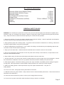
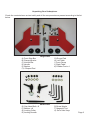
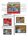
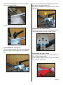
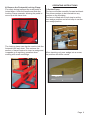
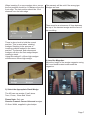
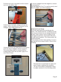
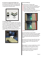
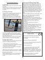
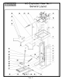
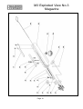
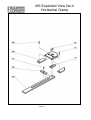
Operators Manual
M3 Manual Underpinner
Only Use Genuine Framers
Corner Universal Wedges
Oure Wedges are 10.3mm
Wide, Available In Softwood
And Hardwood Type.
Framers Corner, Walker Rd, Bardon Hill,
Coalville, Leicestershire LE67 1TU, England
Tel. +44 (0) 1530 516925, Fax. +44 (0) 1530 516929
Email: [email protected]
www.framerscorner.co.uk
M3 Technical Specification
Moulding Width (Using Rebate Clamp)
Moulding Width (Without Clamp)
Moulding Height
Pin Placement from Back Corner
Wedge Sizes
Underpinner Dimensions (WxDxH)
Weight
Warranty
0-60mm
0-100mm
0-100mm
0-110mm
7 to 15mm
730mm x 800mm x 1110mm
30kg
1 year
GENERAL SAFETY RULES
WARNING: Do not attempt to operate the machine until you have read thoroughly and understood completely all instructions, rules, etc. contained in this manual. Failure to comply may result in accidents involving serious personal
injury. Keep this owner's manual and review frequently for continuous safe operation.
1. Know your machine. For your own safety, read the owner's manual carefully. Learn its application and limitations,
as well as specific potential hazards pertinent to this machine.
2. Keep guards in place and in working order. If a guard must be removed for maintenance or cleaning, make sure it
is properly replaced before using the machine again.
3. Remove adjusting keys and spanners. Form a habit of checking to see that the keys and adjusting spanners are
removed from the machine before operating it.
4. Keep your work area clean. Cluttered areas and workbenches increase the chance of an accident.
5. Do not use in dangerous environments. Do not use power tools in damp or wet locations, or expose them to rain.
Keep work areas well illuminated.
6. Keep children away. All visitors should be kept a safe distance from the work area.
7. Use the right tools. Do not force the machine or attachments to do a job for which they are not designed. Contact
the manufacturer or distributor if there is any question about the machine's suitability for a particular job.
8. Wear proper apparel. Avoid loose clothing, gloves, ties, rings, bracelets, and jewellery which could get caught in
moving parts. Non-slip footwear is recommended. Wear protective hair covering to contain long hair.
9. Always use safety glasses. Normal spectacles only have impact resistant lenses. They are not
safety glasses.
10. Do not over-reach. Keep proper footing and balance at all times.
11. Maintain machine in good condition. Keep machine clean for best and safest performance. Follow instructions for
lubrication and maintenance.
12. Disconnect the machine from power or source (or air supply) before servicing.
13. Do not use any power tools while under the effects of drugs, alcohol or medication.
Page 2
Unpacking Your Underpinner
Check the contents have arrived safely and all the components are present according to the list
below.
F
D
A
B
C
H
E
G
J
I
K
Large Parts
A) Front Stop Bar
B) Clamp Adjuster
C) Vertical Bar
D) Handle
E) Washer
F) L Shaped Pad
G) Round Pad
H) Left Table
I) Front Clamp
J) Right Table
K) Rubber Feet x 4
O
P
Q
R
U
S
T
Small Parts
O) Cap Head Bolt x 8
P) Washer x 8
Q) Locking Collar
R) Locking Handle
S) Brass Nipple
T) Magentic Tool
U) Set of Hex Keys
Page 3
MAIN FEATURES OF THE M3 UNDERPINNER
Clamp Height
Adjuster
Top Clamp Lock
Fence Lock
Top Clamp Pad
Front Wedge
Position Lock
Front Clamp
Sliding Fence
Main Table
Side Table
Rear Wedge
Position Lock
Magazine Feeder
Anchor Bolt
ASSEMBLY INSTRUCTIONS
1) Fit the Rubber Feet
Screw 4 feet (K) into threaded holes in the base
of the stand. The feet are adjustable in height.
Use a 13mm spanner to tighten the locking nut,
once the machine has been levelled.
Fit the Handle and Locking Collar (Q) over the
right hand fence bar.
Insert the Front Stop Bar (A) into the hole in the
fence block.
2) Assemble the Fence
Unlock two cap head bolts using the Hex key
supplied. Slide the fence forward until the two
round guide bars are flush with the front of the
fence bracket.
Page 4
Place the Brass Nipple (S) into the threaded
hole in the fence block.
Push the adjusting handle upwards and insert,
from above, the Vertical Bar (C).
Screw the L Shaped Pad (F) onto the end of the
vertical bar.
Screw in the Locking Handle (R).
4) Assemble the Front Clamp
Position the Front Clamp (L) so that one of the
round holes aligns over the Clamp Pusher.
3) Assemble the Top Clamp
Fit the Clamp Adjuster (B) onto the bridge and
secure in place with Washer (E) and Handle
(D).
Clamp
Pusher
5) Assemble the Side Tables
Use 8 Cap Head Bolts (O) and Washers (P) to
fit the 2 Side Tables (H&J).
Use a straight edge to set the level of the tables
flush with the main table.
Page 5
OPERATING INSTRUCTIONS
6) Remove the Footpedal Locking Clamp
For safety during transport the main pedal is
locked down. Undo the handle and slide the
Locking Clamp upwards, allowing the pedal to
move up at the same time.
1) Set the Fence
The fence will slide smoothly forward and back.
This allows wedges to be inserted into any
position on the moulding.
The fence is fitted with a limit stop to set the
front wedge position and a limit stop to set the
rear wedge position.
Fence Lock
Front Stop
The Locking clamp can also be used to lock the
footpedal half way down, This reduces the
amount of travel required to insert a wedge and
is sppeds up th epinning operation when
working with small mouldings.
Rear Stop
When inserting only one wedge into a corner,
the position should be central.
1/2 L
L
Page 6
When inserting 2 or more wedges into a corner
the first position should be 1/4 distance from the
front edge. The last position should be 1/3rd
distance from the back edge.
The warranty will be void if the wrong type
Wedges are use.
There must be a mimumum of 2mm between
the top of the inserted wedge and the face of
the moulding.
1/4 L
1/3 L
L
There is also a lock to hold the current
position. This is used when ‘stacking’
wedges. Stacking is the process of
inserting multiple wedges in the same
position. The second, and subsequent
wedges, will drive the first wedge deeper
creating a stack.
Using this method 2 x10mm high wedges
will become a 20mm high wedge.
2mm
Minimum
4) Load the Magazine
Adjust the height of the wedge magazine using
the round knob located underneath the
magazine.
Single
Wedge
Stacked
Wedges
3) Select the Appropriate Sized Wedge
The M3 can use wedge (V-nail) sizes
7mm, 10mm, 12mm and 15mm.
Please Note: Only use
Genuine Framers Corner Universal wedges
10.3mm Width, supplied in glued strips.
Page 7
Pull back the nylon cord and hook the looped
end over the anchor bolt.
Insert a strip of wedges, sharpened side upwards. When using genuine Framers Corner
Wedges, insert with glued side up.
To remove wedges from the magazine, reverse
the proceedure.
Use the Magnetic Tool (T) to pull the partly used
strip of wedges, out of the magazine.
5) Set the Front Clamp
The front clamp grips the moulding by the
rebate. The clamp holds the moulding securely
even when moving from one wedge position to
another. Place a piece of the moulding to be
used against the fence. Press and hold down
the right hand footpedal. The clamp pusher will
travel backwards.
Fit the clamp over the clamp pusher, in such a
way that tip of the clamp is within 15mm of the
moulding.
Unhook the nylon cord and gently let the spring
push the strip of wedges into the magazine.
Use visual observation to confirm that the
wedges slide under the cap with a gap of no
more than 0.5mm.
m
15
m
0.5mm
Gap
Only
Release the foot pedal and the clamp will
move forward, gripping the moulding.
The tip of the clamp is desgined to allow
for slight variations in the moulding width.
Page 8
6) Choose the Appropriate Rubber Pad
The pinner is supplied with 2 rubber pads. For
flat moulding the round pad is generally better.
For profiled moulding with varying heights the
L shaped pad is generally better.
Round
Pad
8) Insert the Wedge
With all the above settings made:
l Push the fence into the back position
l Press down and hold the right hand pedal
l Place 2 mitred pieces against the fence
l Release the right hand pedal
l Visually check the joint is tight
l Press the left hand pedal firmly all the way
........down until the green light comes on.
L Shape
Pad
7) Set the Top Clamp
It is important to set the height of the top clamp
correctly. Place the moulding to be used against
the fence. Set the gap between the lowest point
of the moulding and the underside of the rubber
pad to 20mm. To adjust the height, press down
and hold the adjusting lever to release the
clamping bar. Slide the clamp up or down as required. Release the clamp adjusting lever.
l Release the left hand pedal
If a second wedge is to be inserted;
Slide the fence and moulding to the next wedge
position and use the left hand footpedal again.
Do not press the right hand pedal until all of the
wedges required have been inserted into the
corner.
20mm
Gap
During the cycle the top clamp will travel down
and contact the moulding, then the driver will
push one wedge into the underside of the
moulding.
Please note: It is recommended that a suitable
glue is always used when making a frame.
Apply a small amount of glue to one of the
mitred ends before loading into the pinner.
The glue will give the frame strength and
ensure it lasts for many years.
Page 9
ROUTINE MAINTENANCE
1) Cleaning
Clean any excess glue from around the wedge
exit point.
Clean the top of the table using a silicone spray
or similar product to allow the fence to slide
smoothly.
2) Clearing a blockage
Occasionally, a wedge may get jammed in the
magazine. It may be possible to pull the
wedges out by hand. If it is firmly stuck,
possibly half in and half out, It is highly likely
that the driver will also be stuck in the raised
position.
Cap
To clear a blockage; remove the cap, using the
hex key provided. Once removed, the driver
should drop back down and the jammed wedge
can easily be removed.
When refitting the cap, ensure the top is flush
with the surface of the surrounding table.
3) Replacing the Driver
The driver is the part which takes the most wear
and will, one day, need replacing.
ii) Use a hex key to remove the Cap.
iii) Undo the hex bolt which secures the bottom
of the driver to the driver holder.
iv) Push the driver up through the main table
and remove it from the top.
When fitting the new driver ensure the V shape
lip is uppermost, with the point of the V towards
the back of the machine.
Before tightening the hex nut, ensure the driver
is firmly pressed against the bottom of the
holder.
4) Changing the Rebate Clamp Cable
i) Remove the 2 Cap Head screws (Part 15)
which hold the Clamp Support Arm (Part 12)
ii) Remove the 2 Cap Head screws (Part 79)
holding the Clamp Cast (Part 62) to the fence.
Drop Clamp Cast down through the machine.
iii) Remove Guide Bar (Part 61) and carefully
remove Clamp Block Spring (Part 82). This will
release the Clamp Block (Part 81) allowing the
Inner Cable to be removed from the Clamp
Bock.
iv) Remove M6 nut (Part 2) on the bottom of the
cable, were the cable passes through the
Clamp Footpedal (Part 33)
v) Remove the M8 nut on the bottom of the
Cable Adjuster (Part 3) where the cable passes
through the bracket on the Floorstand (Part 1).
vi) Remove Inner and Outer Cable from
Floorstand.
vii) Fit the new cable by reversing the
instructions.
viii) Once the cable is replaced, the amount of
movement of the Clamp Block (Part 81) must
be checked. When the footpedal is fully
depressed, the Clamp Block (Part 61) should
move between around 20 mm.
ix) The amount of movement can be adjusted
by the M6 (upper) & M8 (lower) nuts on the
Cable Adjuster (Part 3)
CE Declaration
We declare that Manual Underpinner,
Model M3 conforms with the following
directives:
Machinery Directive 2006/42/EC
And further conforms with the following EU
harmonized standard;
EN ISO 12100:2010
The equipment named above has been
tested and found to comply with the
relevant sections of the above referenced
specification. The machinery complies with
all essential requirements of the directive.
A copy of the declaration is available
by contacting framers corner.
Page 10
UNDERPINNER TROUBLESHOOTING GUIDE
Fault
Possible Cause
Wedges are too wide to load into the magazine Wrong type of wedges
No wedge is inserted into the moulding
Fence does not slide
Top clamp is marking the moulding
Bad joint - Open joint
Moulding is moving during pinning
Faulty wedges
The wedge magazine is empty
Wedge feeder not engaged
Wedge is jammed in cap
Build up of dirt
Wrong pressure pad fitted
Pressure pad is worn or damaged
Bad mitre
Moulding moving during pinning
Cap not flush with table
Extension tables not flush with table
Top clamp not set correctly
Front clamp not set correctly
Remedy
Only Universal type 10.3mm wedges can be
used
Check with wedge supplier
Reload the magazine
Release the nylon cord
Clear the blockage (see page 10)
Lubricate the two sliding fence bars (part no.
45)
Change to alternate shape pad
Replace pad
Check mitring machine
Ensure the base of the moulding is flat
Move the wedge position away from the back
edge
Remove cap and refit it (see page 10)
Reset the tables
Set gap between moulding and pressure pad to
not more than 20mm
Set gap between moulding and clamp to not
more than 15mm
UNDERPINNER TROUBLESHOOTING GUIDE
Fault
Wedges jam in cap
Possible Cause
Wrong wedge size selected
Driver limiter not set correctly
Fence is moving during cycle
Stack is too high
Remedy
Adjust the wedge magazine so the gap
between top of wedge and underside of Cap is
not more than 0.5mm (See page 8)
Ensure wedges are loaded sharpened side up
(Glue side up)
Remove the cap and clean the mechanism
Replace the driver
Press pedal until gren light illuminated
Set gap between moulding and pressure pad to
not more than 20mm
Reset the adjusting screws
Lock the fence when stacking (see page 7)
Use less or smaller size wedges
Wedge position too close to edge
Move the wedge position away from the edge
Wavy grain wood (particularly hardwood)
Hardwood
Driver has come out of holder
Top clamp not set correctly
The wood species is not suitable for stacking
Use specific hardwood wedges
Refit the driver into the holder (see page 10)
Set gap between moulding and pressure pad to
not more than 20mm
Wedges loaded incorrectly
Wedges not fully inserted into moulding
Wedges being driven in too deep
Attempt at stacking fails
Stacking wedges break through side of
moulding
Wedge deforms when inserted
Driver does not return after cycle
Top clamp does not return to start position
Excess build up of glue
The driver is damaged
Pedal stroke incomplete
Top clamp not set correctly
Page 13
Page 14
Page 15
Page 1
M3 Exploded View No.2
Operating Head
Page 1
M3 Exploded View No.3
Magazine
Page 1
M3 Exploded View No.4
Horizontal Clamp
Page 1
Framers Corner, Walker Rd, Bardon Hill,
Coalville, Leicestershire LE67 1TU, England
Tel. +44 (0) 1530 516925, Fax. +44 (0) 1530 516929
Email: [email protected]
www.framerscorner.co.uk