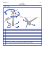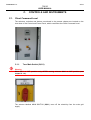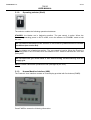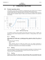
1
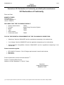
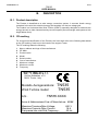
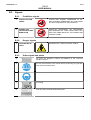
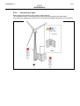
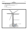
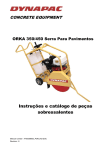
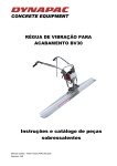
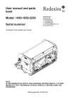
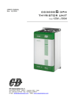
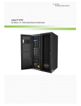
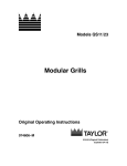
USER MANUAL
WIND TURBINE MODEL TN 535
TRANSLATION OF THE ORIGINAL INSTRUCTIONS
Tozzi Nord S.r.l.
via San Sebastian 21 - Location Interporto - Terminal intermodale - 38121 Trento - Italy
Tel. +39 0461 993383 - Fax +39 0461 956000
TN535_MU_en.02
Tozzi Nord S.r.l.
2/34
TN535
USER MANUAL
Empty page
Tozzi Nord S.r.l.
3/34
TN535
USER MANUAL
TABLE OF CONTENTS
A.
INFORMATION ....................................................................................... 7
A.1.
Symbols ..........................................................................................................................................................7
A.2.
Foreword.........................................................................................................................................................7
A.3.
Information concerning the publication ......................................................................................................7
A.3.1. Purpose of the manual ................................................................................................................................7
A.3.2. Subjects .......................................................................................................................................................8
A.3.3. Exclusions ...................................................................................................................................................8
A.3.4. Structure of the publication ..........................................................................................................................8
A.4.
User information ............................................................................................................................................8
A.4.1. Informed operative ......................................................................................................................................8
A.4.2. User tasks....................................................................................................................................................9
A.4.3. User safety requirements ............................................................................................................................9
A.4.4. Arbitrary modifications .................................................................................................................................9
A.4.5. User’s responsibilities ..................................................................................................................................9
A.4.6. Manufacturer’s responsibilities ....................................................................................................................9
A.5.
Intended Use ................................................................................................................................................10
A.5.1. Conditions of use .......................................................................................................................................10
A.5.2. Environmental Conditions .........................................................................................................................10
A.5.2.1. Cold climate ..........................................................................................................................................11
A.5.2.2. Wind farm influence ..............................................................................................................................11
A.5.2.3. Complex terrain and altitude limitation ..................................................................................................11
A.5.3. Proper use .................................................................................................................................................11
A.5.4. Improper use .............................................................................................................................................12
A.6.
Glossary........................................................................................................................................................13
B.
DESCRIPTION........................................................................................ 15
B.1.
Product description .....................................................................................................................................15
B.2.
CE marking ...................................................................................................................................................15
B.3.
Signals ..........................................................................................................................................................16
B.3.1. Prohibition signals .....................................................................................................................................16
B.3.2. Danger signals...........................................................................................................................................16
B.3.3. Other signals and plates ............................................................................................................................16
B.3.4. Positioning of signs ...................................................................................................................................17
B.4.
Main components ........................................................................................................................................18
B.5.
Yaw ................................................................................................................................................................19
C.
CONTROLS AND INSTRUMENTS ......................................................... 20
C.1.
Client Command Level ................................................................................................................................20
C.1.1. Turn Main Switch (QS11) ..........................................................................................................................20
C.1.2. Operating selector (SA41) .........................................................................................................................21
C.1.3. Human Machine Interface (HMI) ...............................................................................................................21
D.
SAFETY .................................................................................................. 23
Tozzi Nord S.r.l.
4/34
TN535
USER MANUAL
D.1.
Safety Instructions ......................................................................................................................................23
D.2.
Access to the Client Command Level .......................................................................................................24
D.3.
Fire ................................................................................................................................................................25
D.4.
Extreme weather conditions forecast ........................................................................................................25
D.5.
Behaviour in the case of alarm and/or breakdown ..................................................................................27
D.6.
Electrical feed, disconnection, and supply failure ...................................................................................27
E.
OPERATING FUNCTIONS ..................................................................... 28
E.1.
Product operating status ............................................................................................................................28
E.1.1. Parking ......................................................................................................................................................28
E.1.2. Waiting.......................................................................................................................................................28
E.1.3. Starting ......................................................................................................................................................28
E.1.4. Production .................................................................................................................................................29
E.1.5. Shut-down due to insufficient wind ............................................................................................................29
E.1.6. Shut-down due to excessive wind .............................................................................................................29
E.2.
Monitoring and maintenance ......................................................................................................................29
F.
WARRANTY CONDITIONS .................................................................... 30
F.1.
Warranty .......................................................................................................................................................30
G.
TECHNICAL DATA ................................................................................ 31
G.1.
Main data ......................................................................................................................................................31
H.
ALARMS AND WARNINGS ................................................................... 33
H.1.
Alarms ...........................................................................................................................................................33
H.2.
Warnings.......................................................................................................................................................34
Tozzi Nord S.r.l.
5/34
TN535
USER MANUAL
Facsimile of EC Declaration of Conformity provided by the manufacturer:
EC Declaration of Conformity
Place and Date:
MANUFACTURER
Tozzi Nord S.r.l.
Via San Sebastian 21
I-38121 TRENTO
DECLARES THAT THE FOLLOWING PRODUCT:
•
•
•
•
•
•
Generic denomination:
Function:
Model:
Type:
Serial number:
Commercial name:
TN535
Wind Energy Conversion System
TN535
TN535
TN535
FULFILS THE ESSENTIAL REQUIREMENTS OF THE FOLLOWING EC DIRECTIVES:
•
“Machinery” directive 2006/42/EC and the regulations transposing it into national law;
•
“Low Voltage” directive 2006/95/EC and the regulations transposing it into national law;
•
“Electromagnetic Compatibility” directive 2004/108/EC and the regulations transposing it into
national law.
Related standards applied:
•
•
•
IEC 61400-2: Products – Part 2: Design requirements for small wind turbines;
EN12100-1;
EN12100-2.
Person authorised to write the technical dossier (1):
Position: Technical Office Director
Address: Via San Sebastian 21, I-38121 Trento.
Signature
(Legal Representative)
ANDREA TOZZI
(1): The person given the authority within the Community to put together the technical dossier and to make it readily available.
Tozzi Nord S.r.l.
6/34
TN535
USER MANUAL
Tozzi Nord S.r.l.
7/34
TN535
USER MANUAL
A.
INFORMATION
A.1. Symbols
The following symbols are used in this manual to alert the reader to different Danger levels
when using the Product:
Danger
Indicating an imminent hazard, this symbol refers to specific information or procedures
which must be followed exactly in order to avoid risk of death, serious personal injury, or
damage to the Product. It often refers to “residual Risks” or, in any case, dangerous
conditions.
Warning
Indicating a potential hazard, this symbol refers to information or procedures advising the
User on the best way to use the machine in order to prolong its life, avoid damage or loss
of programming data and optimize work in compliance with standards.
Note
Indicating additional information that may be useful for the User.
A.2.
Foreword
Warning
The Products and procedures comply with current European safety of machinery and
safety in the workplace Standards and Directives.
However, it is a priority and compulsory to refer and respect the current Standards and
Directives in the country of use of the Product.
A.3. Information concerning the publication
A.3.1.
Purpose of the manual
The User manual’s purpose is to provide the instructions for:
reading the functional data provided by the Product’s human user interface;
correct interpretation of the functional data;
correct use of the controls and instruments available at the Product’s “Client Command
Level”;
safety.
Tozzi Nord S.r.l.
8/34
TN535
USER MANUAL
A.3.2.
Subjects
The subject of this manual is the User as defined in chapters A.4 and A.6.
A.3.3.
Exclusions
This publication DOES NOT address the following items:
‒ spare parts;
‒ maintenance;
‒ installation;
‒ dismantling of the Product, or of its parts;
‒ repair;
‒ adjustment;
‒ controls and instruments located at the “Service Command Level”.
Such operations must only be carried out by Tozzi Nord trained and authorized personnel.
A.3.4.
Structure of the publication
The manual is composed of separate sections with an initial index showing the sequence of
titles of the sections, the chapters, and the topics addressed with reference to the page
numbers.
Pages are numbered in ascending order, with an indication of the total number of pages in
the document.
In this publication the term “Product”
refers toTozzi Nord’s wind turbine model TN 535
Note
The original language is Italian.
A.4. User information
A.4.1.
Informed operative
The User is defined as an informed operative who is required to read and understand the
instructions contained in the User manual and who may perform certain limited safety
operations described in section D. Safety.
Tozzi Nord S.r.l.
9/34
TN535
USER MANUAL
A.4.2.
User tasks
The User:
- may access the Client Command Level in order to:
- check functional parameters on the display;
- turn off the electricity from the main electrical supply by putting SA41 into position
OFF (see chapter C.1.2.) and then also moving QS11 to OFF (see chapter C.1.1.);
- select the Product’s operating mode by turning SA41 to the required position (see
section C.1.2.);
- may take certain limited safety actions which are described in section "D. Safety";
- must collect information regarding any Dangers, Risks or anomalous situations which
could occur at the Product site;
- must report to Tozzi Nord Technical Assistance Centre any anomalies, alarms or
potentially dangerous and/or unresolved situations.
Tozzi Nord Technical Assistance Centre - Tel. +39 0461 993383.
A.4.3.
User safety requirements
The User must be in good physical and psychological conditions and not have any particular
impediments to correctly reading or controlling the instruments provided (including this User
manual).
A.4.4.
Arbitrary modifications
It is strictly forbidden to modify any part of the Product for any reason whatsoever without the
express authorization of the manufacturer.
Agents or representatives of the manufacturer are not authorized to make any modifications
affecting the User manual except by express written consent from the manufacturer.
The manufacturer declines all liability in relation to unauthorised modifications and reserves
the right to take any actions it deems necessary to protect its interests.
A.4.5.
User’s responsibilities
The User is responsible for any damage to himself, third parties, or objects resulting from:
improper use (defined in chapter A.5.4.) of the Product or any of its parts;
defects caused by failure to comply with the safety instructions (as defined in chapter "D
Safety") and accident prevention regulations.
operations reserved for Tozzi Nord’s trained and authorized personnel.
It is the User’s duty to notify Tozzi Nord Technical Assistance Centre of any dangerous or
anomalous situations which may occur..
A.4.6.
Manufacturer’s responsibilities
The manufacturer is not responsible for any consequences resulting from alterations to the
environmental conditions after installation (e.g. area at Risk of explosion, the presence of
corrosive particles, etc.) or for any incorrect or improper use of the Product such as:
- a method of use not in conformity to that outlined in this publication;
- removal or disabling of active or passive safety devices;
- instances of vandalism by third parties;
- irresponsible conduct not in compliance with good common practice;
- unauthorised modifications.
Tozzi Nord S.r.l.
10/34
TN535
USER MANUAL
A.5. Intended Use
A.5.1.
Conditions of use
The Product is designed to be installed and used only in Danger-free locations (not at risk of
explosions as defined by regulation IEV426-03-02) and those with a class IV wind regime as
defined by standard IEC 61400-2.
Note
The Product’s operating temperature range is between -10°C and 40°C.
Tozzi Nord denies liability for malfunction, injury to persons or damage to objects caused by
failure to use the Product in compliance with this manual.
A.5.2.
Environmental Conditions
The Product is designed to withstand standard Class IV wind as defined in section 6 of
CEI/IEC 61400-2; the Product is designed to be used under the following environmental
conditions:.
Wind conditions:
SWT Class
Reference wind speed Vref
(10 min average, Hub height, recurrence time 50 years)
Annual average wind speed Vave
Turbulence intensity level at 15m/s I15
Dimensionless slope parameter a
(to be used for the calculation of standard deviation turbulence as a
function of VHub and I15)
Expected extreme wind speed Ve50
(3 sec average, Hub height, recurrence time 50 years)
Expected extreme wind speed Ve1
(averaged over 3 s, recurrence time 1 years)
Design wind speed
Other Environmental conditions:
Normal temperature range
Relative humidity of the air
Air density
Solar radiation
Lightening protection system electric scheme described in:
Atmospheric content equivalent to that of a non-polluted inland
atmosphere (see IEC 60721-2-1);
Earthquake model:
TN535 standard Towers and foundations are verified according to
“Decreto Ministeriale 14.01.2008,Testo Unitario - Norme Tecniche per le
Costruzioni” (NTC08), seismic class-II
Electrical network conditions:
Normal supply voltage and range
Normal supply frequency and range
IV
30.0
[m/s]
6.0
0.18
2.0
[m/s]
[-]
[-]
42.0
[m/s]
31.5
[m/s]
8.4
[m/s]
-10<T<40 [°C]
<95% [-]
1.225 [kg/m3]
1000 [W/m2]
[Ref. 4], [Ref. 5], [Ref.6]
400±10% [V]
50±3% [Hz]
Table 1 - Summary of environmental conditions for which TN535 is designed
Tozzi Nord S.r.l.
11/34
TN535
USER MANUAL
Should the installation site’s environmental conditions not comply with the design
conditions, Tozzi Nord cannot be held responsible for any malfunctions, including
but not limited to property damage and/or persons and/or loss of energy yield.
A.5.2.1. Cold climate
Standard Product is rated and tested for a temperature range of between -10°C and +40°C.
When operating at maximum temperatures, power may automatically and temporarily fall,
according to the thermal cycles and environmental conditions. Using the Product outside the
specified temperature range will not result in a risk of injury.
There are several options for equipping the Product for use in a wider temperature range:
heating and/or insulation of the electrical cabinet, additional ventilation in the electrical
cabinet, different types of lubricants, to be implemented according to customer requirements
and the features of the site.
A.5.2.2. Wind farm influence
The loads acting on the Products are calculated for a single Product installation.
In the case of multiple installations, we recommend a minimum distance of 5 to 10 times the
rotor diameters between wind turbines, depending on the prevalent wind directions.
A.5.2.3. Complex terrain and altitude limitation
The loads acting on the Products are calculated for a non-complex terrain site as defined on
GL Guidelines section 4.4.7.
Standard Product can reach the rated power up to 1.000 m above the sea level. The
installation and use of the Product over the above mentioned altitude must be noticed by the
customer to Tozzi Nord in order to quantify the performance losses and define possible
limitation of use.
A.5.3.
Proper use
The Product can be used in all the conditions specifically described in the User Manual.
The operation of the Product is fully automatic and does not require the constant supervision
by operators.
It is not therefore expected that the User take actions for regulation and/or maintenance
purposes.
The User Manual must be available to the User before the Product is put into service.
No components or safety devices relating to the Product must ever be tampered with.
Tozzi Nord S.r.l.
12/34
TN535
USER MANUAL
A.5.4.
Improper use
The User is strictly forbidden to climb the Tower or to attempt any sort of installation,
maintenance or adjustment operation that must be exclusively carried out by Tozzi Nord’s
authorized and trained personnel.
Danger
It is forbidden to carry out any operations which are not described in, or are contrary to,
the contents of this manual.
Tozzi Nord S.r.l.
13/34
TN535
USER MANUAL
A.6. Glossary
Client Command
Level
The first control interface encountered when opening the outer door of the Control and
Power Panel.
Control and
Power Panel
Cabinet containing control and power electrical devices. It is located at the Tower’s base
and it is fixed on the foundations by means of concrete wedge anchors.
Danger
Potential cause of injury or health hazards.
Exposed Person
Anyone who is entirely or partly inside a Hazardous Zone.
Hazardous Zone
Any area inside and/or in the proximity of the Product in which the presence of an
Exposed Person constitutes a Risk for their health and safety.
Housing
Glass Fiber Reinforced Plastic cell or
body covering the chassis and the
generating components.
Hub
Rotary front part of the Product onto
which the blades are installed.
PPE
Personal Protective Equipment
Intended Use
Use of the Product in compliance with the information provided in the User Manual.
Locking Pin
Metal pin preventing pulley and Hub
rotation.
Tozzi Nord S.r.l.
14/34
TN535
USER MANUAL
Nacelle
Part of the Product made up of the
housing and all of the generating
components including the generator,
drive train, chassis, brake assembly
and hub.
Pitch Angle
The angle at which the blade rotates around its longitudinal axis.
Pitch System
System that enables the blade angle
to
be
adjusted,
using
three
connectors (as shown in the picture).
Protective Device
Device designed to reduce risk of injury, on its own or in conjunction with a guard.
Risk
Combination of the probability and degree of seriousness of possible injury or harm to
health in a dangerous situation.
Rotational Speed
Expressed in rpm, this represents the number of rotations per minute made by each of
the blades.
Service
Command Level
The control interface encountered when opening the inner door of the Control and Power
Panel. The inner door is locked by means of a code locking device.
Spinner
Fibreglass
covering
integrating the Hub.
Tower
The Nacelle and Rotor support structure part of the Product, fixed to the ground by a
concrete foundation.
User
An authorised informed operative who has carefully read the Product’s User manual.
Wind Turbine or
Product
Operating machine which converts kinetic energy contained in the wind into electrical
energy.
Yaw
Rotation of the Product on the horizontal plane, in order to follow the direction of the
wind.
Yaw System
System allowing the Nacelle to revolve around the Tower's axis.
component
Tozzi Nord S.r.l.
15/34
TN535
USER MANUAL
B.
DESCRIPTION
B.1. Product description
The Product is classified as a wind energy conversion system. It converts kinetic energy
contained in the wind into electrical energy and supplies it to the low voltage grid.
The Product is a Horizontal Axis Wind Turbine (HAWT) especially designed to maximize the
energy harvest on sites characterized by low wind speed (annual average wind speed at Hub
height below 6m/s).
B.2. CE marking
For unequivocal identification of the Product, the User shall refer to the following data stated
on the CE marking, fixed next to the hatch of the support Tower.
The CE marking states the following:
1
2
3
4
5
6
7
8
9
Name, address and logo of the manufacturer
CE Mark
Product name
Model
Serial number
Year of manufacture
Maximum voltage
Maximum current
Frequency
Tozzi Nord s.r.l.
Via San Sebastian, n°21
38121 Trento - Italy
Modello Aerogeneratore:
Wind Turbine model:
S/N :
TN535
TN535
TN535.XXXX
Anno di fabbricazione/Year of Manufacture:
Massima Tensione/Max Voltage:
Massima Corrente /Max Current:
Frequenza lato rete/Grid Frequency :
xxxx
480 V
18 A
50 Hz
Tozzi Nord S.r.l.
16/34
TN535
USER MANUAL
B.3. Signals
B.3.1.
Prohibition signals
1
PRODUCT ACTION
RADIUS
ACCESS AND TRANSIT FORBIDDEN TO ALL
UNAUTHORIZED PERSONNEL BY TOZZI NORD
WITHIN A 7M RADIUS OF THE PRODUCT
2
OPENING THE
ELECTRICAL PANEL
INNER DOOR
UNSKILLED PERSONNEL OR PERSONNEL
UNAUTHORIZED BY TOZZI NORD MUST NOT
OPEN THE INNER DOOR OF THE POWER AND
CONTROL PANEL
B.3.2.
3
Danger signals
LIVE ELECTRICAL
PARTS
B.3.3.
PRESENCE OF LIVE ELECTRICAL PARTS
Other signals and plates
4
This gives the telephone number and address of the Technical
Assistance Centre.
5
The User must read the User manual before performing any operation
at the Client Command Level.
6
Mandatory use of helmet within a 7m radius from the Product.
7
CE marking.
8
Power and Control Panel identification plate.
Tozzi Nord S.r.l.
17/34
TN535
USER MANUAL
B.3.4.
Positioning of signs
Safety signs are included in the Product’s safety devices.
The materials are able to withstand stress and will last as long as the Product itself.
If any signs are damaged or removed, they must be immediately replaced by the User/client.
Tozzi Nord S.r.l.
18/34
TN535
USER MANUAL
B.4. Main components
The Product is composed of the following main elements:
A Upwind three-bladed horizontal axis rotor.
B Nacelle.
C Tower.
D Control and Power Panel.
A
B
C
D
Tozzi Nord S.r.l.
19/34
TN535
USER MANUAL
B.5. Yaw
A
Front side
B
Rear side
C
Left-hand side
D
Right-hand side
E
Rotor anti-clockwise rotation
F
Rotor clockwise rotation
G
Nacelle frontal area (Hub side)
H
Nacelle rear area
X
Rotational axis of the Rotor. This axis must be positioned at a 90° angle with the position to the
ladder (C side) during installation/maintenance operations (ladder mounted).
Y
View point
Tozzi Nord S.r.l.
20/34
TN535
USER MANUAL
C.
CONTROLS AND INSTRUMENTS
C.1. Client Command Level
The selectors, switches and buttons mentioned in the present chapter are located on the
inner door of the Control and Power Panel, which constitutes the Client Command Level.
C.1.1.
Turn Main Switch (QS11)
Warning
Move QS11 to OFF position only AFTER turning selector SA41 to OFF position (see
chapter C.1.2.).
The selector labelled MAIN SWITCH (QS11) turns off the electricity from the main grid
supply.
Tozzi Nord S.r.l.
21/34
TN535
USER MANUAL
C.1.2.
Operating selector (SA41)
The selector enables the following operational statuses:
STANDBY: the blades are in feathering position. The yaw control is active. When the
Product is generating power in AUTO mode, move the selector to STANDBY mode to halt
the rotor.
We recommend activation of this function in the event of predicted adverse weather
conditions (see section D.4).
OFF: the blades are in feathering position. The yaw control is inactive. When the Product is
generating power in AUTO mode, move the selector to OFF mode to halt both the rotor and
yaw system.
We recommended you switch SA41 to OFF before turning off the electricity from the
supply grid.
AUTO: Product’s automatic operational mode (managed by the PLC).
C.1.3.
Human Machine Interface (HMI)
The Product’s User interface consists of a text display provided with five buttons (F1÷F5).
Press F1÷F5 to access the following information:
Tozzi Nord S.r.l.
22/34
TN535
USER MANUAL
F1: Current values
Rotor speed:
Power:
Wind speed:
Wind direction:
Number of Nacelle revolutions:
Temperature of the generator:
Vibration:
Auxiliary supply voltage:
Software version:
rpm
kW
m/s
°
°C
g
VDC
text
F2: Historical data
Total energy produced.
Total energy produced during the year.
Total energy produced during the current month.
Total energy produced from midnight onwards on the current day.
Total hours of inverter functioning.
F3: Monthly values
The monthly values for energy Production and average wind speed.
F4: Warnings
Reports any currently active warnings.
F5: Product status and alarm messages
Reports any currently active alarms.
Tozzi Nord S.r.l.
23/34
TN535
USER MANUAL
D.
SAFETY
D.1. Safety Instructions
The Product is fully automatic and does not require any operator supervision.
The User is not therefore expected to operate the Product for regulation and/or maintenance
purposes.
The User may access the Client Command Level in order to:
- check functional parameters on the display;
- turn off the electricity from the main electrical supply by putting SA41 into position
OFF (see chapter C.1.2.) and then also moving QS11 to OFF (see chapter C.1.1.);
- select the Product’s operating mode by turning SA41 to the required position (see
section C.1.2.);
Warning
Do not tamper with any safety device or any other component of the Product.
The User is strongly advised not to stand or position vehicles within the action radius of the
Product (the radius extends in a circle approximately 7m around the Tower). In any case, a
protective helmet must always be worn.
In case of obvious malfunctioning of the Product, unusual noise, ice accretion, significant
atmospheric events, seismic events, fire or floods, it is COMPULSORY to keep away from
the Product.
Tozzi Nord S.r.l.
24/34
TN535
USER MANUAL
Warning
Access to the Tower, installation, maintenance, or control operations must be carried out
exclusively by Tozzi Nord trained and authorized personnel.
Any Product malfunction must be reported by the User to the Tozzi Nord technical assistance
office.
D.2. Access to the Client Command Level
The User can access to the Client Command Level by opening the outer door of the Control
and Power Panel, positioned at the base of the Tower.
The Client Command Level allows the User to monitor the Product’s functional data.
Tozzi Nord S.r.l.
25/34
TN535
USER MANUAL
Warning
Opening the inner door of the Control and Power Panel is restricted to Tozzi Nord trained
and authorized personnel. At the Service Command Level there are live components with
voltage exceeding 600VdC and 400V AC.
The User is responsible for keeping the Control and Power Panel’s outer door
properly closed. The manufacturer declines any liability for any direct or indirect
damage due to vandalism or water entry resulting from the improper closure of the
outer door.
D.3. Fire
If the Product or of any of the associated system components should catch fire, the User is
advised to turn off the electricity from the main grid supply as long as this action does not put
the User at Risk. The relevant authorities must be noticed in all cases.
D.4. Extreme weather conditions forecast
In the event of extreme wind speed forecast (above force 9 on the Beaufort scale), the User
is advised to put the Product into standby mode using the SA41 switch (see chapter C.1.2.).
Refer to the following table to evaluate the effect of the wind:
Tozzi Nord S.r.l.
26/34
TN535
USER MANUAL
Wind force
Wind speed
Effect of the wind
Beaufort
degree
Name
m/s
km/h
0÷0.2
1
0
Calm
1
Light movement of
air
0.3÷1.5
1÷5
Direction of the wind indicated only by the movement
of smoke, but not by a flag
2
Light wind
1.6÷3.3
6÷11
You feel the wind on your face, the leaves are
rustling, the flag is moving
3
Light breeze
3.4÷5.4
12÷19
Leaves and branches are moving, the wind can
stretch light flags out
4
Moderate breeze
5.5÷7.9
20÷28
The wind raises dust and loose papers, moving
branches and small sticks
5
Fresh breeze
8.0÷10.7
29÷38
Small broad-leaved trees start to swing
Ripples rise on lakes
6
Strong wind
10.8÷13.8
39÷49
Strong branches are moving, telegraphic lines whistle,
it is hard to use umbrellas
7
Tight wind
13.9÷17.1
50÷61
All trees are moving, it is difficult to move against the
wind
8
Stormy wind
17.2÷20.7
62÷74
Branches break off trees, it is difficult to walk outside
9
Storm
20.8÷24.4
75÷88
Minor damage to houses (destroying the covers of
chimneys and tiles)
10
Violent storm
24.5÷28.4
89÷102
Uprooted trees, damage to houses
Calm, smoke rises in a straight line
Tozzi Nord S.r.l.
27/34
TN535
USER MANUAL
D.5. Behaviour in the case of alarm and/or breakdown
Warning
If the alarm flashes, the User is forbidden to restart the Product without the authorization
of the Tozzi Nord Technical Assistance Centre.
In the case of alarm or breakdown, please urgently report the following information to the
Tozzi Nord Technical Assistance Centre:
- Product serial number;
- Product model;
- Site name;
- Product status.
Tozzi Nord Technical Assistance Centre
Tozzi Nord S.r.l
Registered Office: Via San Sebastian 21
Location Interporto - Terminal Intermodale - 38121 Trento - Italy
Tel. +39 0461 993383 - Fax +39 0461 956000
email: [email protected]
D.6. Electrical feed, disconnection, and supply failure
In normal operating conditions, the feed for the control system of the Product is derived from
the mains electricity supply.
The selector labelled MAIN SWITCH (QS11), positioned on the storage door of the electrical
control cabinet, is used to disconnect the Product from the mains supply.
Warning
You are advised FIRST to move selector SA41 to OFF (see chapter C.1.2.) and then QS11
to OFF (see chapter C.1.1.).
After turning selector MAIN SWITCH (QS11), or following a power
cut, the Product will use its own internal back-up system to set
park/safety status (turning the blade Pitch Angle until it reaches
feathering position). If the electricity supply is not restored within
twenty (20) minutes, the controller will turn off the control system to
preserve battery life.
When the electricity supply is restored, or when selector MAIN
SWITCH (QS11) is returned to ON, the Product will restart
automatically.
Tozzi Nord S.r.l.
28/34
TN535
USER MANUAL
E.
E.1.
OPERATING FUNCTIONS
Product operating status
The Product’s control logic is entrusted to a programmable logic controller (PLC) and based
on about 50 parameters monitored by means of estimates and/or special sensors.
The figure below shows the operating range of the Product. The controller always keeps the
Product inside the consented range. All start-up and shutdown procedures are performed
automatically.
Figure 1 – TN535 operating range.
It is possible to identify 6 main statuses during which the Product is active. In addition, the
Product may enter certain temporary statuses of transition or testing (battery tests, sensor
tests, etc.).
E.1.1.
Parking
When parked, the blades are in feathering position (collective blade Pitch Angle of
approximately 90°). In this mode, the rotor speed i s equivalent to 0.6 rpm for every m/s of
wind.
This status may occur following:
‒ excessive wind;
‒ error;
‒ cable unwinding (when the cables are wound too far, the Product implements a
procedure to unwind them. It is not therefore an anomaly if the Product puts itself into
park position and executes a few revolutions of the Nacelle).
E.1.2.
Waiting
In the event that the wind speed is below that required for activation, the Product will place
itself with the blades in the waiting position (collective blade Pitch Angle at about 40°).
The rotor is free. The yaw control is active.
E.1.3.
Starting
Whether the average rotor speed (over 100s) exceeds 11 rpm or the instantaneous rotor
speed exceeds 20 rpm, the turbine will arrange the blades in working position (collective
Tozzi Nord S.r.l.
29/34
TN535
USER MANUAL
blade Pitch Angle about 2°). The inverters start up at the same time. The yaw control is
active.
E.1.4.
Production
Up to a rotor speed of 66 rpm the Product keep the blades fixed in starting position,
maintaining a point of maximum efficiency by means of the control system which regulates
the power converter as required.
Once a speed of 66 rpm is reached, the PLC control algorithm maintains the rotor at a
constant speed by controlling the blade’s pitch as required. Once a speed of 66 rpm is
reached, the power output from the converter will also remain constant.
In production status the yaw control is active.
E.1.5.
Shut-down due to insufficient wind
If the rotor speed drops below 22 rpm (average speed over 360 second) while the Product is
operating in production status or if the instantaneous rotor speed drops below 8 rpm, the
Product will go into the status of waiting.
The yaw control is active.
E.1.6.
Shut-down due to excessive wind
If the wind speed exceeds 16 m/s (average speed over 480 s) or reaches an instantaneous
wind speed exceeding 22 m/s while the Product is operating in production status, the Product
will activate the safe status of parking.
The PLC will automatically return to starting and production statuses.
The yaw control is active.
E.2.
Monitoring and maintenance
Performance and safety attributes of the Product are ensured by means of monitoring and
maintenance.
Only Tozzi Nord trained and authorized personnel are qualified to carry out monitoring
procedures and maintenance operations.
Tozzi Nord S.r.l.
30/34
TN535
USER MANUAL
F.
F.1.
WARRANTY CONDITIONS
Warranty
Tozzi Nord provides a 24 month guarantee on the Product starting from the date of signing
the Installation Report.
The guarantee conditions are set out in the Product Sales Contract Agreement.
Tozzi Nord S.r.l.
31/34
TN535
USER MANUAL
G.
TECHNICAL DATA
G.1. Main data
Turbine Architecture:
Type
Upwind rotor with active pitch control and active yaw
control
Direction of rotation
Number of blades
Rotor diameter
Hub height
Rated power
Power regulation
Cut-in wind speed
Cut-out wind speed
Rated wind speed
Rotor diameter
Rotor swept area
Clockwise (upwind view)
3
13.2 m
15-18-24 m
9.9 kW
Active pitch (pitch to feather)
2.5 m/s
16 m/s
6.7 m/s
13.2 m
136.7 m2
Rotor
Type
Blade length
Material
Lightning protection
Hub
LWTB535
6.344 m
GFRP
Optional
Fixed (no tilt)
Drive train
Transmission
Main bearing
High speed shaft Rotational Speed
Belt drive
Single-row ball bearing
225-750 rpm
Low speed shaft Rotational Speed
Grid feed Inverter
20-66 rpm
ABB ACS M1
Generator
Nominal power
Type
Protection
Insulation class
11.0 kVA
Permanent Magnets Synchronous Generator 8 poles
IP54
F
Yaw System
Yaw Type
Active yaw control
Yaw Rate
3.35 deg/s
Controller
Tozzi Nord S.r.l.
32/34
TN535
USER MANUAL
Type
Remote monitoring
UPS
Breaking System
Aerodynamic brake
PLC
Tozzi Nord SCADA / Real Time Viewer
2x12V BACK UP batteries
Rotor lock
Collective pitch, (3 pitch linear actuator rates: 14, 21,
48 mm/s)
Passive centrifugal system that brings blades to
braking position
Metal pin inserted for maintenance
Tower
Tower height
Tower type
Design wind class
14.6m-17.6m-23.6m
Polygonal steel Tower, 16 sides, 2 sections
IV
Weights
Nacelle (excluding Rotor and Hub)
Rotor (including Hub)
Tower
783 kg
332 kg
1300kg (14.6m) - 1750kg (17.6m) - 3350kg (23.6m)
Noise Emission
Max LWA @10m/s
87.1 dB
Redundant aerodynamic brake
Tozzi Nord S.r.l.
33/34
TN535
USER MANUAL
H.
ALARMS AND WARNINGS
H.1. Alarms
F5 display mode reports any anomalous situations regarding the operational status of the
Product. Alarm status implies that the Product is out of operation.
Please report any alarm found by reading F5 display mode to the Tozzi Nord Technical
Assistance Centre. The alarm list is reported below.
Code
Description
1 Alarm-Flag Standby
2 Alarm-Flag Off
3 Alarm-Flag Manual
6 Alarm-Flag Emergency stop activated
8 Alarm-Flag Cable wound up to the right
9 Alarm-Flag Cable wound up to the left
10 Alarm-Flag Software flag "Machine off"
11 Alarm-Flag Switch clock "Machine off"
12 Alarm-Flag Strong wind shut down, by average
13 Alarm-Flag Strong wind shut down, by peak
16 Alarm-Flag Supply 28VDC grid
17 Alarm-Flag Supply 28VDC linear drive
18 Alarm-Flag Supply 28VDC to low (Level 2)
19 Alarm-Flag Invalid wind direction measurement
20 Alarm-Flag Grid monitoring interface triggered
28 Alarm-Flag Runtime of yawing too long
29 Alarm-Flag Sensor 1 for rotor speed measurement defective
30 Alarm-Flag Sensor 2 for rotor speed measurement defective
31 Alarm-Flag Winding protection of yawing motor triggered
32 Alarm-Flag Test battery voltage
33 Alarm-Flag Function of vibration sensor
34 Alarm-Flag Failure of generator temperature measurement
35 Alarm-Flag System test failed
36 Alarm-Flag Supply 28VDC for sensors
37 Alarm-Flag Supply 28VDC to low (Level 1)
40 Alarm-Flag A yawing sensor is defective
41 Alarm-Flag Generator winding problem
42 Alarm-Flag Excessive rotor speed 3
51 Alarm-Flag Could not find parking position
52 Alarm-Flag Could not find waiting position
53 Alarm-Flag A linear drive position sensor defective
54 Alarm-Flag Runtime linear drive "OUT" too long
55 Alarm-Flag Runtime linear drive "BACK" too long
56 Alarm-Flag Inverter
57 Alarm-Flag Overtemperature generator
58 Alarm-Flag Speed rotor/generator not synchronous
60 Alarm-Flag Excessive rotor speed 1
61 Alarm-Flag Excessive rotor speed 2
62 Alarm-Flag Vibration sensor triggered
63 Alarm-Flag Generator Short Circuit
64 Alarm-Flag Fault Grid Inverter
65 Alarm-Flag Fault Gen Inverter
66 Alarm-Flag PLC WD Engaged
Tozzi Nord S.r.l.
34/34
TN535
USER MANUAL
H.2. Warnings
F4 display mode reports any anomalous situations regarding the operational status of the
Product (warnings). A warning does not imply that the Product should be put out of
operation.
Please report any warning found by reading F4 display mode to the Tozzi Nord Technical
Assistance Centre.
The warning list is reported below.
Code
Description
83 Warning-Flag Wind vane not mooving
84 Warning-Flag Change PLC battery
85 Warning-Flag TimeOut communication inverter
87 Warning-Flag Test battery capacity
89 Warning-Flag reduced rotor speed
90 Warning-Flag Icing condition
91 Warning-Flag Derating for over-temperature
92 Warning-Flag Derating for vibration