1
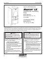
User’s Manual - Mascot LX Boilers and Water Heaters
the building’s heating loop. Only after the value shifts
position will the firing sequence begin.
3.4Modulation Control
The control uses a PID algorithm to adjust
the firing rate of the boiler as the control point is
approached. The goal of the control is to operate at a
minimum firing rate to match the load on the appliance.
3.5Pump Control
The boiler pump is active anytime there is a call for
heat applied to the control. When there is a central heat
call the system pump relay is active. If there is a DHW
call while the central heat call is active the system pump
turns off. This happens because of domestic hot water
priority, which forces the control to satisfy the domestic
water demand prior to the hydronic demand. When the
last heat demand is satisfied the boiler pump enters an
overrun time.
3.6High Limit
The control uses a dual thermistor sensor to
monitor the Mascot LX’s maximum temperature. The
high limit sensor is installed in the outlet water. A dual
thermistor sensor is used, so that the two temperatures
can be monitored and compared to confirm accuracy.
The control will automatically reduce the firing of the
Mascot LX to prevent the high limit from tripping. The
high limit setpoint is not adjustable.
3.7 Stack Temperature
The stack temperature is a dual thermistor sensor
and is limit rated. The control compares each of the
temperature readings to determine accuracy. The stack
sensor is used as a limiting feature to avoid excessive
temperatures in the venting.
3.8 Domestic Hot Water Temperature
The domestic hot water temperature sensor is used
to control the DHW temperature. The DHW setpoint can
be adjusted through the Base / Home state and the User
Mode. On LX ‘C’ or Combi models, the DHW sensor is
pre-installed in the DHW exchanger. On LX ‘H’ or Heat
models the DHW can be can be controlled by an aquastat
or optional DHW sensor installed in an indirect tank.
3.9 Cascade Auto Configuration
To operate up to 8 boilers in cascade, the boilers
must be “daisy chained” together using Modbus
terminals A, B and GND, located on the boilers terminal
block. The wiring should be completed with at least
three wire shielded cable with ground. The ground wire
should be connected to a suitable chassis ground on one
end of the daisy chain only. Wire each boilers terminal
A in series with the next boilers terminal A until all are
Page 5
connected. Repeat this process for Terminal B and
GND.
To configure the control system, identify which
boiler is going to be the “master” boiler for the cascade
system and navigate to installer parameter P06,
“Cascade Address”. Set the address to “0” and press
and hold “select”. When “auto cfg” appears on the
display press “select” to start the auto configuration
process. The auto configuration process will find all
boilers connected to the “master” boiler and assign
addresses. When auto configuration is complete the
display should show “boilr #” where # is the total
number of boilers found in the cascade system.
The final steps are to set the individual setpoints
in the cascade system, which include P07 “Cascade
Setpoint”, P08 “Cascade off Hysteresis” and P09
“Cascade on hysteresis”. These variables must be set to
the appropriate values for the installation. When setting
P09 “cascade on hysteresis” the value should NOT be
less than P08 “Cascade off Hysteresis” as P09 references
the off point (P07+ P08) as the starting point for the on
hysteresis. An example of this is shown below.
Correct settings:
P07 = 120°F
P08 = 10°F
P09 = 20°F
With these setting the modulation point is 120°F
The off point is 120°F + 10°F = 130°F
The on point is 130°F – 20°F = 110°F
Incorrect settings:
P07 = 120°F
P08 = 10°F
P09 = 5°F
With these setting the modulation point is 120°F
The off point is 120°F + 10°F = 130°F
The on point is 130°F – 5°F = 125°F
In this case the boiler is turning back on prior to
reaching the modulation point, which could lead to
short cycling.
3.9.1 Cascade Manual Configuration
In some applications it may be necessary to
configure the cascade system manually. To do this, the
boilers should be wired as shown in the Auto Cascade
section of the manual. Then each individual control in
the cascade must have a specific address assigned by
adjusting P06 “ Cascade address” on each boiler. To
start, identify the boiler that will be the “master” boiler.
Navigate to parameter P06 “cascade address” set to
“0” and press “Select” (do NOT press and hold select).
Then press and hold select.
Repeat this process for each boiler in the cascade
setting each address to a unique number.
The last step is to adjust all of the setpoints
for the installation application as shown in the Auto
cascade section of the manual.