1
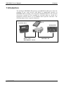
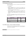
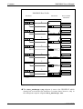
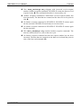
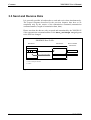
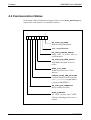
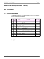
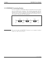
XPS/XPS-E User's Manual COMSOFT XPS/XPS-E User's Manual Version: Date: Order No.: 1.2 04. May 1999 4003-7-G00-H-E COMSOFT GmbH Wachhausstraße 5a D-76227 Karlsruhe Phone: Fax Hotline: Email: Internet address: +49/ 721/ 9497- 0 +49/ 721/ 9497- 299 [email protected] www.comsoft.de This documentation has been drawn up carefully, but, in spite of all efforts, errors may occur. Information from the part of our customers that will help to improve comprehensibility of the document and remove errors will be appreciated. The information contained therein can be amended without prior notice and does not represent any obligation on the part of COMSOFT. We do not assume any kind of responsibility for possible inconsistencies and their consequences. This work including all its parts is copyrighted. Every usage of it which lies beyond the tight limits of the copyright are prohibited and punishable. This applies especially to copies, translations, microfilms as well as to feeding into and processing in electronic systems. All other product or company names mentioned in this document may present trademarks of the respective owners. XPS/XPS-E User's Manual Contents Contents 1 Introduction.................................................................................................... 1 2 Setting into Operation ................................................................................... 2 2.1 Connection of the Gateway...................................................................... 3 2.1.1 XPS Desk Model .............................................................................. 3 2.1.2 XPS-E Top Hat Rail Model.............................................................. 4 2.1.3 Proceeding ........................................................................................ 5 2.2 Test of PROFIBUS Connection ............................................................... 5 2.3 Parameterisation....................................................................................... 6 2.4 set_prm Parameterisation ......................................................................... 7 2.4.1 GSD File........................................................................................... 8 2.4.2 Slave_diag Device Diagnostics ........................................................ 9 2.4.3 Parameter Description .................................................................... 10 2.4.3.1 Baud Rate................................................................................ 10 2.4.3.2 Character Transmission Mode................................................ 10 2.4.3.3 Handshake Flow Control ........................................................ 11 2.4.3.4 XOFF_timeout – Timeout of Software Handshake................ 11 2.4.3.5 DP-Data Transmission Mode ................................................. 12 2.4.3.6 Extended Gateway configuration data.................................... 12 2.4.3.7 Trigger character for Serial triggert mode .............................. 13 3 Data Exchange.............................................................................................. 14 3.1 Send Data ............................................................................................... 15 3.2 Receive Data .......................................................................................... 15 3.2.1 Poll Mode ....................................................................................... 16 3.2.2 Serial triggered Mode..................................................................... 18 3.2.3 Request Mode................................................................................. 19 3.3 Send and Receive Data........................................................................... 22 4 Status and Error Messages ......................................................................... 23 4.1 External Device Diagnostics .................................................................. 23 4.2 Communication Status ........................................................................... 24 5 Connector Assignment and Cabling........................................................... 25 5.1 PROFIBUS............................................................................................. 25 5.1.1 Connector Assignment ................................................................... 25 5.1.2 PROFIBUS Terminating Resistor .................................................. 26 5.1.3 Cabling ........................................................................................... 27 COMSOFT i Contents XPS/XPS-E User's Manual 5.2 Serial Interface ....................................................................................... 28 5.2.1 Connector Assignment RS232 (XPS and XPS-E).......................... 28 5.2.2 Cabling RS232................................................................................ 29 5.2.2.1 Cabling without Hardware Handshake................................... 29 5.2.2.2 Cabling with Hardware Handshake ........................................ 29 5.2.3 Connector Assignment RS422/485 (XPS-E only) ......................... 30 5.2.4 Cabling RS422 without Hardware Handshake............................... 30 5.2.5 Cabling RS422 with Hardware Handshake.................................... 31 6 Frequently Asked Questions: FAQ ............................................................ 32 7 Technical Data.............................................................................................. 33 7.1 XPS ........................................................................................................ 33 7.1.1 PROFIBUS-DP Interface ............................................................... 33 7.1.2 RS232 Interface .............................................................................. 34 7.1.3 Connection...................................................................................... 34 7.1.4 Operating Indicators and Controls ................................................. 34 7.1.5 Technical Data................................................................................ 35 7.2 XPS-E..................................................................................................... 36 7.2.1 PROFIBUS-DP Interface ............................................................... 36 7.2.2 Serial Interface ............................................................................... 37 7.2.3 Connection...................................................................................... 37 7.2.4 Operating Indicators and Controls ................................................. 37 7.2.5 Technical Data................................................................................ 38 8 PROFIBUS-DP Certificate ......................................................................... 39 9 CE- Conformity Declaration....................................................................... 40 ii COMSOFT XPS/XPS-E User's Manual Contents List of Tables Table 1: set_prm .............................................................................................7 Table 2: slave_diag ......................................................................................9 Table 3: Baud Rate of Serial Interface Octet 12 ............................................10 Table 4: Character Transmission Modes Octet 13 .........................................10 Table 5: Handshake Modes Octet 14 .............................................................11 Table 6: Data Transmission Modes Octet 16 .................................................12 Table 7: ext. configuration byte Octet 17.......................................................12 Table 8: Triggerzeichen Octett 18 ....................................................................13 Table 9: Data Transmission Format at data_exchange_req ....................14 Table 10: Data Transmission Format at data_exchange_res ..................14 Table 11: Pin Assignment PROFIBUS.............................................................25 Table 12: Connector Assignment RS232 Interface ..........................................28 Table 13: Connector Assignment RS422/485 Interface ...................................30 COMSOFT iii Contents XPS/XPS-E User's Manual List of Figures Figure 1: Typical Connection of an XPS/XPS-E Gateway ................................1 Figure 2: Connectors and Interfaces of XPS ......................................................3 Figure 3: Connectors and Interfaces of XPS-E...................................................4 Figure 4: Data Reception in Poll Mode ............................................................16 Figure 5: Receive data in serial triggered mode (trigger character : 0x0A) ....18 Figure 6: Data Reception in Request Mode......................................................20 Figure 7: Combined Send- and Receive Request .............................................22 Figure 8: Byte Definition of external Device Diagnostics ...............................23 Figure 9: Byte Definition of Communication Status ........................................24 Figure 10: Assignment of PROFIBUS Terminator Type A .............................26 Figure 11: Connection of a PROFIBUS-DP Slave within a Segment ..............27 Figure 12: RS232 Cabling without Hardware Handshake................................29 Figure 13: RS232 Cabling with Hardware Handshake.....................................29 Figure 14: RS422 Cabling with Hardware Handshake.....................................30 Figure 15: RS422 Cabling with Hardware Handshake.....................................31 Figure 16: PROFIBUS-DP Certificate No. Z00284 .........................................39 iv COMSOFT XPS/XPS-E User's Manual Contents 1 Introduction The intelligent PROFIBUS-DP gateways of COMSOFT's XPS series allow the coupling of any serial devices with RS232 or RS422/485 interface to PROFIBUS-DP according to the European Standard EN50170. The protocol conversions required for the coupling are executed either by means of a transparent universal driver or by loadable device-specific converters. The following figure shows a typical connection: Serial End Device XPS-E DP-MASTER XPS RS232 – XPS RS232/RS422 – XPS-E PROFIBUS-DP Figure 1: Typical Connection of an XPS/XPS-E Gateway COMSOFT 1 Contents XPS/XPS-E User's Manual 2 Setting into Operation When developing the XPS products, COMSOFT put great stress on an easy installation. Following this aim, no external devices, e.g. configuration tools on a PC are required to execute the configuration. All connections are realised by D-SUB connectors, power plug (EN 60320) or spring clip terminals which can all be accessed and loosened easily. The PROFIBUS station address is set via coding switches. All further settings are done via UserParameter of the SetParam telegram of PROFIBUS-DP. This parameterisation is executed, simplified by the deliverable GSD file either via the configuration tool of the connected PROFIBUS-DP Master or by the user program. 2 COMSOFT XPS/XPS-E User's Manual Contents 2.1 Connection of the Gateway 2.1.1 XPS Desk Model Front Side Status LED Address Switch RS232Interface PROFIBUS-DP Interface Terminator ON/OFF Power Supply Rear Side Figure 2: Connectors and Interfaces of XPS COMSOFT 3 Contents XPS/XPS-E User's Manual 2.1.2 XPS-E Top Hat Rail Model PROFIBUS Interface Serial Interface Address Switch RUN-LED BUS-FAIL-LED MODE-LED TX-LED RX-LED Power Supply Connector Figure 3: Connectors and Interfaces of XPS-E 4 COMSOFT XPS/XPS-E User's Manual Contents 2.1.3 Proceeding By executing the following steps, the XPS/XPS-E Gateway can be set into operation: 1. Connect XPS/XPS-E to PROFIBUS by using a standard PROFIBUS cable with corresponding D-SUB PROFIBUS connector. For the connector assignment please refer to chapter Connector Assignment and follow the Installation Guidelines for PROFIBUS (No. 2.112, PNO). 2. Connect the serial end device with XPS/XPS-E (Connector Assignment refer to 5.2). 3. Check your PROFIBUS network with regard to an unused Slave address and adjust this free address at the coding switch of XPS/XPS-E. 4. Plug in the power supply. In case of XPS this is done by means of a power plug (EN 60320) at the rear side of the device. The power supply of the XPS-E is connected by spring clips at the front side. As soon as the device is powered, the Status/Busfail LED is flashing red. Note The Status/Busfail LED is flashing red until the device is parameterised and configured. In this status, no data exchange can take place (neither send nor receive). Only after successful parameterisation and configuration the Status/Run LED is flashing green. Now, the device is ready for data exchange. 2.2 Test of PROFIBUS Connection If you have a PROFIBUS-DP configuration tool, you can test the PROFIBUS connection to the XPS/XPS-E Gateway. For this purpose, load the deliverable GSD file into your configuration tool. The DP Master shall now configure XPS/XPS-E. If this configuration is successful, the Status/Run LED is flashing green. If you do not have a PROFIBUS-DP configuration tool or if you wish to change the pre-defined parameters (User_Prm_Data) in the GSD file, please refer to the following chapters for the parameterisation. COMSOFT 5 Contents XPS/XPS-E User's Manual 2.3 Parameterisation The parameterisation data of XPS/XPS-E consists of 7 DP-Slave standard bytes and 16 device-specific parameters bytes (User_Prm_data, -> user_prm_len = 16). As user diagnostic data, 8 additional diagnostics bytes are available. (diag_len = 8). 1. For initialisation of XPS/XPS-E send a set_prm telegram. For this purpose, use the parameters for PROFIBUS-DP and the serial interface described in chapter 2.4. 2. Check the parameterisation with slave_diag. 3. Then use the command chk_cfg to configure the XPS/XPS-E. Prior to that, the configuration can be read with the command get_cfg from XPS/XPS-E. If chk_cfg is executed directly after the initialisation, the maximum data_exchange telegram length is loaded from XPS/XPE-E. For shorter data_exchange telegram length select one of the possible configurations which are defined in the GSD file or select those arbitrarily according to the PROFIBUS-DP standard. After successful parameterisation XPS/XPS-E is prepared for data exchange. The Status/Run LED is now flashing green. Note You can verify the parameterisation and configuration telegram by means of slave_diag. In the following, only those parameters are described that are required for operating the XPS/XPS-E. For the significance of the remaining PROFIBUSDP standard parameters please refer to the standard EN50170 and the GSD file. 6 COMSOFT XPS/XPS-E User's Manual Contents 2.4 set_prm Parameterisation The Bytes 1-7 are PROFIBUS-DP standard parameters, Byte 8-23 are devicespecific parameters (usr_prm). Octet Parameter Name Value 1 Station_status 0x80* 2 WD_fact_1 0x00 3 WD_fact_2 0x00 4 Min TSDR 55 5 Ident_Number [0] 0x95 6 Ident_Number [1] 0x10 7 Group_Ident 0x00 8..11 Reserved --- 12 Baud Rate setting of serial interface See Table 3 13 Character Transmission Mode of serial interface See Table 4 14 Handshake setting of serial interface See Table 5 15 XOFF-Timeout of serial interface See 2.4.3.4 16 Receive Mode of PROFIBUS interface See Table 6 18 Trigger character for serial triggered mode See Table 8 (usually LF (0x0A)) 19..23 Reserved --- Table 1: set_prm ( ) * COMSOFT Freeze_Req and Sync-Req are not supported. 7 Contents XPS/XPS-E User's Manual 2.4.1 GSD File Next to standard parameters the parameters for the serial interface are included in the GSD file. They are listed under the User_Prm_Data. The values correspond to those described under chapter 2.3. A modification of these parameters can be made by any kind of ASCII editor. Please note that the number of parameters must not be changed and that the first four and last six parameter bytes are to be set to 0. In the following, the default settings of the GSD for serial interfaces of XPS/XPS-E are listed. 9600 Baud / 8Bit / No Parity / 1 Stopbit / no Handshake / no Timeout / PollMode / RS232-Mode This corresponds to the following entry in the GSD file: User_Prm_Data = 0 0 0 0 96 56 78 0 80 0 0 0 0 0 0 0 8 COMSOFT XPS/XPS-E User's Manual Contents 2.4.2 Slave_diag Device Diagnostics Octet 1-7 are PROFIBUS-DP Standard, Octet 8-14 are the device-specific diagnostics parameters (external diagnostics). Octet Parameter Value 1 Station_status_1 Bit7 Bit6 Bit5 Bit4 Bit3 Bit2 Bit1 Bit0 Diag.Master_Lock Diag.Prm_Fault Diag.Invalid_Slave_Response Diag.Not_Supported Diag.Ext_Diag Diag.Cfg_Fault Diag.Station_Not_Ready Diag.Station_Non_Existent 2 Station_status_2 Bit7 Bit6 Bit5 Bit4 Bit3 Bit2 Bit1 Bit0 Diag.Deactivated reserved Diag.Sync_Mode Diag.Freeze_Mode Diag.WD_On must be set to 1 Diag.Stat_Diag Diag.Prm_Req 3 Station_status_3 Bit7 Diag.Ext_Diag_Overflow Bit6..0 reserved 4 Master_Address Master address or 0xFF, if Slave is not yet parameterised. 5 Ident_Number[0] 0x95 6 Ident_Number[1] 0x10 7 Number of ext. diagnostic bytes 8 8 XPS/XPS-E state See 4.1 9 Baud Rate of the serial interface See 2.4.3.1 10 Character Transmission Mode of serial interface See 2.4.3.2 11 Handshake setting serial interface See 2.4.3.3 12 XOFF-Timeout of serial interface See 2.4.3.4 13 Receive Mode of DP- interface See 2.4.3.5 14 Setting of driver physics of serial interface (RS232/485) See 2.4.3.6 15 Trigger character for Serial triggerd Mode 0x0A Table 2: slave_diag COMSOFT 9 Contents XPS/XPS-E User's Manual 2.4.3 Parameter Description The parameters marked with (*) are the default values. These are used if inadmissible parameters are entered during parameterisation. 2.4.3.1 Baud Rate Baud Rate (bit/s) Value (dec) Value (hex) 150 1 0x01 300 3 0x03 600 6 0x06 1.200 12 0x0C 2.400 24 0x18 4.800 48 0x30 9.600 * 96 0x60 19.200 192 0xC0 Table 3: Baud Rate of Serial Interface Octet 12 2.4.3.2 Character Transmission Mode Transmission Mode 10 Value (hex) 8 Data bits, No Parity, 1 Stopbit (8N1) * 56 0x38 7 Data bits, No Parity, 2 Stopbits (7N2) 78 0x4E 7 Data bits, Even Parity, 1 Stopbit (7E1) 69 0x45 7 Data bits, Odd Parity, 1 Stopbit (7O1) 79 0x4F Table 4: Character Transmission Modes Note Value (dec) Octet 13 The operating mode: 7 data bits, No Parity, 1 StopBit is not supported. COMSOFT XPS/XPS-E User's Manual Contents 2.4.3.3 Handshake Flow Control If data is exchanged via the serial interface, XPS/XPS-E supports the following modes for the handshake: • No Handshake • Hardware Handshake. The receive data flow can be controlled at the respective device by setting or re-setting the RTS-/CONTROL signal (CTS/INDICATION=0 -> no sending). A corresponding example for cabling can be found under chapter 5.2.2 and 5.2.3. • Software Handshake. The receive data flow can be stopped by the respective device by sending the control character XOFF (0x13). The sending procedure will only be re-started if a XON character (0x11) is received or a Timeout (XOFF-Timeout) for the receipt of the XON character. The interruption of the sending procedure or the XOFF timeout is shown in the status byte of XPS/XPS-E (see chapter 4.2) by means of the bit XOFF_CTS_FLAG. Handshake Mode Value (dec) Value (hex) Hardware Handshake (CTS, RTS for RS232 72 and CONTROL/INDICATION for RS422) 0x48 Software Handshake 83 0x53 No Handshake * 78 0x4E Table 5: Handshake Modes Octet 14 2.4.3.4 XOFF_timeout – Timeout of Software Handshake The XOFF timeout is calculated by means of VALUE * 100ms. This value is entered into Octet15 of the parameterisation data. If no software handshake is entered, this value is insignificant. Note COMSOFT If the value 0 is given, the timeout is set to 10 seconds. 11 Contents XPS/XPS-E User's Manual 2.4.3.5 DP-Data Transmission Mode To offer the user several possibilities to adapt his application optimally to the gateway functionality of XPS/XPS-E, 3 data transmission modes can be used. The corresponding description is found under chapter 3. Data Transmission Modes Value (dec) Value (hex) Poll Mode * 80 0x50 Request Mode 82 0x52 Serial triggered Mode 83 0x53 Table 6: Data Transmission Modes Octet 16 2.4.3.6 Extended Gateway configuration data ext. Configuration byte Bit Function Bit7 ..Bit2 Reserved Bit1 Double baud rate Bit0 RS232(0)<->RS422(1) Table 7: ext. configuration byte Octet 17 BIT0: RS232<->RS422 – Serial interface physics With this parameter the interface physics can be set to RS232(0) or RS485(1). This parameter is only applicable for XPS-E. The desktop model (XPS) does only have an RS232 physics. BIT1: double Baudrate Setting this bit doubles the baudrate for the serial interface Exp: A selected baudrate of 19200 Baud can be increased to 38400 Baud by setting this bit. BIT7 – Bit2: reserved 12 COMSOFT XPS/XPS-E User's Manual Contents 2.4.3.7 Trigger character for Serial triggert mode Here the trigger character for the serial triggerd mode is set. If the seriell receive data stream contains the same sign, all received data up to this character are sent to the DP-Master inclusive the trigger character. Triggerzeichen LF * Wert (dez) 10 Wert (hex) 0x0A Wert (ASCII) LF Table 8: Triggerzeichen Octett 18 COMSOFT 13 Contents XPS/XPS-E User's Manual 3 Data Exchange Data exchange of XPS/XPS-E is exclusively realised by means of the PROFIBUS-DP service data_exchange. The data to be sent by the master correspond to the output data of data_exchange.req, the data received correspond to the input data of data_exchange.res. For each send or receive job, at max. 240 Bytes are available while 3 Bytes are headers and the remaining 237 Bytes are user data. If more than 237 Bytes user data shall be sent or received, the application on part of the PROFIBUS-DP Master must split this job into several telegrams. The data transmission format used from/to XPS/XPS-E has the following structure: Byte Telegram Element Value Range (dec) 1 Receive request number (only request mode) 0 – 255 (see 3.2) 2 Send request number 0 – 255 (see 3.1) 3 Data length N of the following user data 0 – 237* 4..4+N Telegram data (user data) 0 – 255 Table 9: Data Transmission Format at data_exchange_req Byte Telegram Element Value Range (dec) 1 Status of XPS/XPS-E 0 – 255 (see 4.2) 2 Receive Confirmation number of XPS/XPS-E 0 – 255 (see 3.2) 3 Data length N of the following user data 0 – 237* 4..4+N Telegram data (user data) 0 – 255 Table 10: Data Transmission Format at data_exchange_res (*) maximum number of user data depends on how the DP-Master has configured XPS/XPS-E via the chk_cfg service. Data can be arbitrary characters in the value range 0..255. This however is only valid if XON/XOFF is not used as handshake. 14 COMSOFT XPS/XPS-E User's Manual Contents 3.1 Send Data To send data via XPS/XPS-E onto a serial end device, the send flag of XPS/XPS-E must be reset (ref. 4.2 Communication Status, Bit 0 = 0), as otherwise the send data to XPS/XPS-E will be discarded. For a send job, the following data must be included into the telegram. • Send job number. This job number must be different for each send procedure. Reasonably, the value should be incremented by 1 at every send procedure. • Send data length. If the data length is set to 0, no data is sent via the serial interface. Otherwise this byte includes the number of the following user data. • Send data (user data) 3.2 Receive Data XPE/XPS-E has a 2Kbyte receive data buffer to temporarily store data received from the connected serial end device. For data transfer to the PROFIBUS-DP Master the operating modes Poll mode and Request-Mode are available. The mode will be selected during parameterisation of XPS/XPS-E by the Master (ref. 2.4.3.5). In the Poll mode available receive data will be sent at every data_exchange.req with the corresponding data_exchange.res from XPS/XPS-E to the PROFIBUS-DP Master. In the Request mode the XPS/XPS-E sends this data only if in data_exchange.req a defined byte has been changed (the receive request number). Thus, the polling of existing receive data can be controlled by the Master. The request mode is recommended for Masters that are polling the slaves cyclically to generate a process image. (application may be too slow to process the current data of the process image). COMSOFT 15 Contents XPS/XPS-E User's Manual 3.2.1 Poll Mode In this mode XPS/XPS-E returns with every data_exchange the data received up to the present time. Apart from the receive data and their lengths a receive data number is entered into the telegram. This confirmation number is automatically incremented if new receive data is available in the telegram. If the receive telegram does not contain new data (data length = 0), the confirmation number remains unchanged. Note: If this mode is used when the Master is generating a Process Image according to a Poll List it must be paid attention that this Poll List can be read quickly enough as with every data_exchange the process image will be overwritten. This may cause loss of data on part of the application. Loss of data can be noticed when the confirmation number is not subsequent. PROFIBUS Data Traffic DP-Master X XPS/XPS-E TE DATA_EXCHANGE.REQ DATA_EXCHANGE.RES Receive Buffer XPS/XPS-E S 1 2 TE STDAT X S 2 5 STDAT X S 2 0 EN EN X S 3 2 EN X = Receive Request Number S = Status Figure 4: Data Reception in Poll Mode 16 COMSOFT XPS/XPS-E User's Manual Contents The telegrams mentioned above can either be started automatically by the Master (cyclically during automatic polling) or by the application. Note: The receive request number (X) in Poll Mode may not be set. ❶ The data_exchange.req telegram is sent to XPS/XPS-E. XPS/XPS-E has already received the first characters at the interface. It returns them in the response telegram data_exchange.res to the Master. The confirmation is incremented by 1 and the length of the reception data is entered. Moreover, the status (S) of XPS/XPS-E is returned. ❷ New data_exchange.req telegram. XPS/XPS-E returns the new data by incrementing the confirmation number by 1. ❸ As response telegram to the data_exchange.req telegram, XPS/XPS-E enters the old confirmation number as no new data has been received at the serial interface. The receive data length is set to 0. ❹ XPS/XPS-E has again received new data. The confirmation number is incremented by one and the data returned correspondingly by the data_exchange.res telegram to the Master. If no time guarantee can be given and if data loss has to be excluded under all circumstances, XPS/XPS-E must be run in the request mode. COMSOFT 17 Contents XPS/XPS-E User's Manual 3.2.2 Serial triggered Mode In serial triggered mode XPS/XPS-E waits for the termination of the receive data by the trigger character defined within the external user parameters of XPS/XPS-E (usually LF in ASCII-strings). The receive confirmation number is not increased as long as no trigger character is received. After the trigger character is received the Data Exchange Resp.-buffer is updated with the received data inclusive the trigger character. The data Exchange Resp.-buffer does not change as long as the next trigger character is received. PROFIBUS Data traffic DP-Master X XPS/XPS-E 1.: X "T01",0x0A DATA_EXCHANGE.REQ DATA_EXCHANGE.RES Receive buffer XPS/XPS-E S 1 4 "T01",0x0A 2.: "T2" S 1 4 "T01",0x0A 3.: X S 1 4 "T01",0x0A X 4.: 0x0A S 2 3 "T2",0x0A X = Receive request number S = Status Figure 5: Receive data in serial triggered mode (trigger character : 0x0A) Hinweis: 18 Please note, that it is not necessary to set the receive request number (X) in polling/serial Mode COMSOFT XPS/XPS-E User's Manual Contents 1. The data_exchange.req is transmitted to the XPS/XPS-E. XPS/XPS-E has already received data via the serial interface. This data are transmitted with data_exchange.res back to the DP-Master. The receive confirmation number is incremented and data length and status are updated. 2. Next data_exchange.req service. XPS/PS-E responds with the old data. New data are in fact received, but they do not contain the trigger character. 3. Next data_exchange.req service. XPS/PS-E responds with the old data, because no further serial data were received. 4. Next data_exchange.req service. XPS/PS-E has received in the meantime the serial trigger character. The receive confirmation number is incremented, data length, status and data_exchange.res buffer are updated with the actual data. 3.2.3 Request Mode In the request mode the XPS/XPS-E only sends receive data if a modified receive-request number is contained in the request telegram. The data are not returned in the first response telegram but in the response telegram of the subsequent data_exchange service. This means that the data are returned always only in the subsequent cycle of the request. If the response telegram contains received data, the XPS/XPS-E confirmation number is incremented by one and returned in the response telegram (as in the poll mode). Note: COMSOFT If this mode is used while the master is automatically polling the slaves according to the poll list, the data that have been received last remain in the process image. 19 Contents XPS/XPS-E User's Manual PROFIBUS Data Traffic DP-Master 1 XPS/XPS-E TE DATA_EXCHANGE.REQ DATA_EXCHANGE.RES Receive Buffer XPS/XPS-E S 0 0 STDAT 2 S 1 2 TE 3 S 2 5 STDAT EN EN 3 S 2 5 STDAT EN EN 3 S 2 5 STDAT EN EN 4 S 2 5 STDAT 4 S 3 2 EN S = Status Figure 6: Data Reception in Request Mode The data_exchange.req telegram is sent to the XPS/XPS-E which already has received the first characters. It returns them, however, only in the subsequent response telegram data_exchange.res. 20 COMSOFT XPS/XPS-E User's Manual Contents New data_exchange.req telegram with increased receive-request number (further reception command). XPS/XPS-E returns the data received at point in time . The confirmation number is increased by one. Another reception command to XPS/XPS-E (receive-request number has been increased). The data that are returned are the data received at point in time . No further reception command to XPS/XPS-E. XPS/XPS-E returns again the last sent data. XPS/XPS-E has already received new data. No further reception command to XPS/XPS-E. XPS/XPS-E returns again the last sent data. This data_exchange.req contains another reception command. The data are returned, however, only at the next cycle. No further reception command because the request number has not been increased. The data that are returned are the data received until the point in time of the last read command ( ). COMSOFT 21 Contents XPS/XPS-E User's Manual 3.3 Send and Receive Data It is generally possible in both modes to send and receive data simultaneously. The request telegrams described in the previous chapters then have to be completed only by the entries of the transmission command (transmission command number, length of transmission data, data). Please note that the data are only accepted and transmitted by the XPS/XPS-E if the transmission command number in the data_exchange.req telegram to the XPS has changed. PROFIBUS Data Traffic DP-Master 1 X 5 SEN XPS/XPS-E TE DATA_EXCHANGE.REQ DATA_EXCHANGE.RES Receive Buffer XPS/XPS-E S 1 2 TE X = Receive Request Number S = Status Figure 7: Combined Send- and Receive Request 22 COMSOFT XPS/XPS-E User's Manual Contents 4 Status and Error Messages 4.1 External Device Diagnostics External device diagnostics can be realised by means of the service slave_diag Octet 8 of the response telegram contains the device status and is encoded as follows: 7 Octet 8 x x x x x x 0 x RS_PORT_CFG_ERROR Invalid parameter at parameterisation of serial interface. not significant Figure 8: Byte Definition of external Device Diagnostics COMSOFT 23 Contents XPS/XPS-E User's Manual 4.2 Communication Status In the status of the confirmation telegram of the service data_exchange the status of the serial interface is encoded as follows: 7 0 RS_PORT_TX_DATA Data are being transmitted. not significant RS_PORT_PARITY_ERROR Parity error of receive data of serial interface. RS_PORT_RX_DATA_AVAIL XPS/XPS-E has data in receive buffer. XOFF_CTS_FLAG XOFF was received or CTS is inactive. OUTPUT_DATA_LEN_FAILURE user data length exceeds maximal data_exchange length minus 3 (on part of PROFIBUS) RS_PORT_RX_OVERFLOW Receive buffer overflow XOFF_TIMEOUT No XON received after XOFFTimeout. Sending process was restarted. Figure 9: Byte Definition of Communication Status 24 COMSOFT XPS/XPS-E User's Manual Contents 5 Connector Assignment and Cabling 5.1 PROFIBUS 5.1.1 Connector Assignment The PROFIBUS connection is executed according to EN50170 as 9-pin female D-SUB with the following assignment: Pin RS485 Ref. Signal Function Direction 1 - - Shielding - 2 - - NC - 3 B/B´ RxD/TxD-P Data (+) I/O 4 - CNTR-P Control character (+) O 5 C/C´ DGND Data Ground - 6 - VP Supply for Terminator (+5V) - 7 - - NC - 8 A/A´ RxD/TxD-N Data (-) I/O 9 - CNTR-N O Control character (-) Table 11: Pin Assignment PROFIBUS O = Output I = Input COMSOFT 25 Contents XPS/XPS-E User's Manual 5.1.2 PROFIBUS Terminating Resistor For correct operation of XPS/XPS-E both bus terminations of the line segment must be provided with a terminator. This terminator must match with the impedance level of the line. Typically, in case of new PROFIBUS installations, Type A will be used. The assignment of the individual terminating resistors of the terminator is depicted in the following figure. 6 +5V 390R 3 Data+ 220R 8 Data- 390R 5 0V Figure 10: Assignment of PROFIBUS Terminator Type A Note 26 You can also order the PROFIBUS Terminator in pre-configured condition (Order No.: 4000-7-002-H, Type A). COMSOFT XPS/XPS-E User's Manual Contents 5.1.3 Cabling M T T S1 S2 .... Sn T= Terminator M=Master S=Slave, n ≤ 31 Figure 11: Connection of a PROFIBUS-DP Slave within a Segment If no terminator with independent power supply shall be used (active terminator), the termination must be realised directly at the last stations of the bus. This station must then supply the terminator with power. For details regarding the PROFIBUS installation please refer to the PROFIBUS Installation Guidelines of the PROFIBUS User Organisation (PNO, Order No.: 2.112). NOTE COMSOFT In case of XPS a bus termination is integrated and can be activated via the switch at the front side of the device. 27 Contents XPS/XPS-E User's Manual 5.2 Serial Interface 5.2.1 Connector Assignment RS232 (XPS and XPS-E) The connection is realised via a 9-pin D-SUB plug. Pin Signal FNI CCITT Function Direction 1 DCD M5 109 Data Carrier Detect I 2 RxD D2 104 Receive Data I 3 TxD D1 103 Transmit Data O 4 DTR S1 108.2 Data Terminal Ready O 5 GND E2 102 Ground --- 6 DSR M1 107 Data Set Ready I 7 RTS S2 105 Request to Send O 8 CTS M2 106 Clear To Send I 9 --- --- --- Not connected --- Table 12: Connector Assignment RS232 Interface O = Output I = Input 28 COMSOFT XPS/XPS-E User's Manual Contents 5.2.2 Cabling RS232 5.2.2.1 Cabling without Hardware Handshake XPS/XPS-E Assignment 9pol Pin Signal End Device Assignment 9pol 25pol Signal Pin Pin 2 3 RxD TxD TxD RxD 2 3 3 2 5 GND GND 5 7 Figure 12: RS232 Cabling without Hardware Handshake 5.2.2.2 Cabling with Hardware Handshake XPS/XPS-E Assignment 9pol Pin Signal End Device Assignment 9pol 25pol Signal Pin Pin 2 3 7 8 RxD TxD RTS CTS TxD RxD RTS CTS 2 3 7 8 3 2 4 5 5 GND GND 5 7 Figure 13: RS232 Cabling with Hardware Handshake COMSOFT 29 Contents XPS/XPS-E User's Manual 5.2.3 Connector Assignment RS422/485 (XPS-E only) The connection is realised via a 9-pin D-SUB plug. Pin Signal Function Direction 1 I(B) Indicate (-) I 2 R(A) Receive Data (+) I 3 T(A) Transmit Data (+) O 4 T(B) Transmit Data (-) O 5 G Ground --- 6 R(B) Receive data (-) I 7 C(A) Control (+) O 8 I(A) Indicate (+) I 9 C(B) Control (-) O Table 13: Connector Assignment RS422/485 Interface O = Output I = Input 5.2.4 Cabling RS422 without Hardware Handshake XPS/XPS-E Assignment 9pol Pin Signal End Device Assignment 15pol Signal Pin 3 4 2 6 T(A) T(B) R(A) R(B) R(B) R(A) T(B) T(A) 11 4 9 2 5 GND GND 8 Figure 14: RS422 Cabling with Hardware Handshake 30 COMSOFT XPS/XPS-E User's Manual Contents 5.2.5 Cabling RS422 with Hardware Handshake XPS/XPS-E Assignment 9pol Pin Signal End Device Assignment 15pol Signal Pin 3 4 2 6 8 1 7 9 T(A) T(B) R(A) R(B) I(A) I(B) C(A) C(B) R(B) R(A) T(B) T(A) C(B) C(A) I(B) I(A) 11 4 9 2 10 3 12 5 5 GND GND 8 Figure 15: RS422 Cabling with Hardware Handshake COMSOFT 31 Contents XPS/XPS-E User's Manual 6 Frequently Asked Questions: FAQ This section is treating the most frequent application problems and their solutions. The most current questions and answers can be found under http://www.comsoft.de DP-Master Status Message: Status 0xC2 (SAP/Service not activated) Make sure that the parameterisation sequence of the parameterisation described in section 2.3 has correctly been executed. If necessary, repeat parameterisation. DP-Master Status message: Status 0xC3 (no acknowledge) Check the following points: • Does the station address of the XPS/XPS-E correspond to the setting of the PROFIBUS Master device? • Are the bus parameters set correctly? • Is the bus terminated correctly (switch position of the terminator integrated in XPS)? • Has XPS/XPS-E been connected correctly? DP-Master Status message: Status 0xC4 (bad telegram) Check the terminating resistors at the bus. Pay attention to the switch position of the terminating resistor at the XPS. 32 COMSOFT XPS/XPS-E User's Manual Contents 7 Technical Data 7.1 XPS 7.1.1 PROFIBUS-DP Interface COMSOFT Transmission protocol: PROFIBUS-DP according to EN50170-3 Slave coupler Transmission rates: 9.6Kbit/s , 19.2Kbit/s, 93.75Kbit/s, 187.5Kbit/s, 500Kbit/s, 1.5Mbit/s, 3Mbit/s automatic adjustment Potential segregation: Opto-coupler interface and DC/DC transducer Isolation voltage U>500V Terminating resistor: TYP A, to be activated via slide switch Operating modes: Sync_Req and Freeze_Req are not supported. Addresses: 1 - 99 by encoding switch Identification Number: 0x9510 Parameterisation Data: 23 Byte (16 Byte User Parameter) Diagnostics information: 6 Byte System diagnostics acc. to standard 8 Byte device-specific diagnostics Data_Exchange Buffer: 4 - 240 Byte I/O arbitrarily selectable (3 Byte with Header functionality). PNO certified: Z00284 33 Contents XPS/XPS-E User's Manual 7.1.2 RS232 Interface Interface: RS232 interface with handshake signals (RTS, CTS) Transmission rates: 150bit/s, 300bit/s, 600bit/s, 1.200bit/s, 2.400bit/s, 4.800bit/s, 9.600bit/s, 19.200bit/s Character Transmission: 8N1, 7N2, 7E1, 7O1 Handshake: HW (RTS/CTS), SW(XON/XOFF), none XOFF Timeout: Adjustable to max. 25,5 seconds Operating mode: Poll mode, Request mode, serial triggerd mode Receive buffer: 2 KByte Potential segregation: none 7.1.3 Connection Power Supply: international power plug (EN 60320) PROFIBUS-DP: 9-pin female D-SUB (DIN 41652) RS232: 9-pin male D-SUB with shield (DIN 41652) 7.1.4 Operating Indicators and Controls 34 PROFIBUS Status LED: “green“ means RUN “red“ means BUSFAIL PROFIBUS address: window in coding switch COMSOFT XPS/XPS-E User's Manual Contents 7.1.5 Technical Data COMSOFT Case: steel sheet, zinc-coated and lacquered Dimensions: 175mm x 145mm x 45mm (LxWxH) Weight: 1kg Power supply: 230VAC / 25mA Storage temperature: -25°C .. +70°C Temperature range: 0°C .. +55°C non-condensing Protection class: 1 Protection kind: IP52 Standards: CE, EN60950, EN50081-2, EN50082-2 35 Contents XPS/XPS-E User's Manual 7.2 XPS-E 7.2.1 PROFIBUS-DP Interface 36 Transmission protocol: PROFIBUS-DP acc. to EN50170-3 Slave coupler Transmission rates: 9.6kbit/s, 19.2kbit/s, 93.75kbit/s, 187.5kbit/s, 500kbit/s, 1.5Mbit/s, 3Mbit/s, 6Mbit/s, 12Mbit/s automatic adjustment Potential segregation: Opto-coupler interface and DC/DC transducer Isolation voltage U>500V Operating modes: Sync_Req and Freeze_Req are not supported. Addressing: 1 - 99 by coding switch Identification number: 0x9510 Parameterisation data: 23 Byte (16 Byte user parameters) Diagnostics information: 6 Byte system diagnostics acc. to standard 8 Byte device-specific diagnostics Data_Exchange Buffer: 4 - 240 Byte I/O selectable (3 Bytes with header functionality). COMSOFT XPS/XPS-E User's Manual Contents 7.2.2 Serial Interface Interface: RS232 interface with Handshake signals (RTS, CTS). RS422/485 interface with Handshake signals (CONTROL, INDICATION). Interface physics can be adjusted via PROFIBUS by means of User_Parameter. Transmission rates: 150bit/s, 300bit/s, 600bit/s, 1.200bit/s, 2.400bit/s, 4.800bit/s, 9.600bit/s, 19.200bit/s Character transmission: 8N1, 7N2, 7E1, 7O1 Handshake: HW (RTS/CTS, CONTROL/INDICATION), SW(XON/XOFF), none XOFF Timeout: adjustable to max. 25,5 seconds Data transmission modes: Poll mode, Request mode, serial triggered mode Receive buffer 2 KByte Potential segregation: optional 7.2.3 Connection Power supply: 2-pin spring clip 2,5mm2 without ferrule 1,5mm2 with ferrule PROFIBUS-DP: 9-pin female D-SUB (DIN 41652) RS-PORT: 9-pin male D-SUB (DIN 41652) 7.2.4 Operating Indicators and Controls COMSOFT PROFIBUS Status LEDs: “green” means RUN “red” means BUSFAIL RS-PORT Status LED: RxD “red” corresponds to: data will be received TxD “red“ corresponds to: data will be sent Hardware physics “red” corresponds to: RS232 mode PROFIBUS address: window at coding switch 37 Contents XPS/XPS-E User's Manual 7.2.5 Technical Data 38 Case: synthetic profile with aluminium front panel, lacquered Dimensions: 126mm x 90mm x 38mm (LxWxH) Weight: 190g Voltage range: 18 – 30VDC Power assumption: 100mA (24VDC) Storage temperature: -25°C .. +70°C Temperature: 0°C .. +55°C non condensing Protection class: 1 Protection kind: IP52 Standards: CE, EN60950, EN50081-2, EN50082-2 COMSOFT XPS/XPS-E User's Manual Contents 8 PROFIBUS-DP Certificate Figure 16: PROFIBUS-DP Certificate No. Z00284 COMSOFT 39 Contents XPS/XPS-E User's Manual 9 CE- Conformity Declaration We herewith declare that the PROFIBUS / RS232-RS422/485 Gateway XPS, XPS-E corresponds to the requirements stated in the EU standards 89/336/EWG and 92/31/EWG. The board corresponds to the following standards: EN 50082-2 and EN 55022 Manufacturer: COMSOFT GmbH Wachhausstr. 5a D-76227 Karlsruhe 40 COMSOFT


![13. Discovery [Zabbix]](http://vs1.manualzilla.com/store/data/005964234_1-ff5a66c4f34dfcd582e5cd37b27ba780-150x150.png)