1
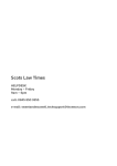
______________ USER’S MANUAL Solo Flight Panel______________ User’s Manual Rev 1.6 October 2015 VirtualFly, S.L. tel..+34 938333301 [email protected] 1 ______________ USER’S MANUAL Solo Flight Panel______________ TABLE OF CONTENTS 1. 2. 3. 4. 5. 6. 7. 8. 9. 10. IDENTIFICATION OF ELEMENTS INSTALLATION START‐UP SELECTION OF PANEL TYPE (according to plane) ANALOGIC PANEL INDICATORS RADIOSTACK PANEL MULTIPLE SOLOFLIGHTPANEL OR MULTIPLE MFS COMPUTER ON THE SAME NETWORK TROUBLESHOOTING WHAT IS NEW ON THIS VERSION REMOTE SESSION VirtualFly, S.L. tel..+34 938333301 [email protected] 2 ______________ USER’S MANUAL Solo Flight Panel______________ 1. IDENTIFICATION OF ELEMENTS Packaging contents: 1‐ SoloFlightPanel (SFP) (1 unit). 2‐ Electrical power cable (1 unit). 3‐ Network cable (1 unit). 4‐ “Pro Flight 3 Lever Throttle” adaptor panel (1 unit). 5‐ “Pro Flight 3 Lever Throttle” screws (4 units). 6‐ Memory Stick (1unit). Content: User's manual, pluggin SFPConnect, FSUIPC and TeamViewer. 7‐ Quick Start Guide (1 unit). 1 2 5 3 4 7 6 It is important to save all parts you are not going to use in case you need them in the future VirtualFly, S.L. tel..+34 938333301 [email protected] 3 ______________ USER’S MANUAL Solo Flight Panel______________ 2. INSTALLATION The SoloFlightPanel, hereinafter referred to as “SFP”, has been technologically developed to be fully plug&play. It connects easily to any computer running the Microsoft Flight Simulator 2004 (9) or FSX (10) hereinafter referred to as “MFS”. Still, we’ll give you a series of steps to follow to install your panel. Place the panel on the table where it is to be used or on the SFP support; in the latter case, follow its instruction manual. A C B F Connect the power cable (2), to the SFP connector (A). Connect the network cable (3 or 4) to the connector (B). Make sure the power switch (C) is OFF‐0. Connect the power cable (2) to a 110‐220 VAC outlet. Connect the network cable (3) to the computer's MFS LAN outlet. You have two options, direct or through the LAN network. OPTION 1: direct OPTION 2: Through LAN network MFS computer MFS computer VirtualFly, S.L. tel..+34 938333301 [email protected] 4 ______________ USER’S MANUAL Solo Flight Panel______________ Copy the "SFPConnect" file from the Memory Stick in the MFS desktop computer. If you don't have the FSUIPC software in the MFS computer, you must have al least the free version installed. From the Memory Stick execute the "Install FSUIPC4.exe" for FSX or "Install FSUIPC.exe" for FS2004. During the installation will appear a registration window, you must to ignore the registration pushing "Not Now". Restart MFS after the installation. ACTIVATING THE SFP: Switch the power switch (C) to ON‐I. Press the push‐button (F) to start the "Windows7" operating system of the computer from the SFP. At this time, the "Windows7" operating system and all programs found in the SFP computer will start automatically. (It is very important that SFP not be disconnected or "Windows7" stopped while the programs are loading. Doing so may cause problems with booting in the future). The SFP is ready to operate after 60 seconds, you must to see the analog gauges are shown on SFP. See Chapter 3 for connecting the SFP with your computer’s MFS. DEACTIVATING THE SFP: Press the push‐button (F) to stop the "Windows7" from the SFP computer, wait for Windows to stop totally. Once "Window7" has stopped, switch the power switch (C) to OFF‐0. VirtualFly, S.L. tel..+34 938333301 [email protected] 5 ______________ USER’S MANUAL Solo Flight Panel______________ EXCLUSIVELY FOR “PRO FLIGHT YOKE” AND/OR SAITEK “PRO FLIGHT 3 LEVER THROTTLE” USERS If you are using Pro Flight Yoke by SAITEK, you can fit it under the SFP as shown in the picture below. If using the Pro Flight 3 Lever Throttle by SAITEK, you can attach it to the SFP by following these simple steps: 1. Stop the SFP computer, wait for "Windows7" to stop totally. 2. Unplug the power cable (2) from the electrical outlet. 3. Unscrew the 4 screws of the panel (D) on the bottom right. 4. Use the 4 screws (6) to mount your Lever Throttle to the panel (5). Pass the cable through the hole marked with a red arrow. 5. Remove the plastic cap from the rear hole (E). 6. Pass the end of the cable into the SFP until it comes out the rear hole (E). 7. Screw the whole Pro Flight 3 Lever Throttle + panel (5) to the SFP. D E VirtualFly, S.L. tel..+34 938333301 [email protected] 6 ______________ USER’S MANUAL Solo Flight Panel______________ 3. START UP The SFP incorporates a mini‐computer that is to be connected to the MFS computer using the previously mentioned LAN cable 3. It is important to note that in no case should you access or manage the SFP mini‐computer. Activate the SFP like is indicated in chapter 2. Deactivate the switch MASTER AVIONICS on left of the panel. Startup the MFS software. To establish the connection between the MFS computer and the SFP you must to execute the file "SFPConnect.exe" from the MFS desktop computer (see chapter 2). If you have the Windows FireWall activated, a warning permission to communicate with networks appears, you must to click "Allow Access". Once the connection is established, you should see an image like the right: In this case the pluggin is connected to MFS and the SFP In this case the pluggin is searching the MFS and the SFP At the top “This PC” indicates if the software Flight Simulator 2004/X is detected. Only "Connected" will appear when you have initiated Microsoft Flight Simulator. At the bellow “Solo Flight Panel” indicates the connection with the Solo Flight Panel. VirtualFly, S.L. tel..+34 938333301 [email protected] 7 ______________ USER’S MANUAL Solo Flight Panel______________ From this moment we can already appreciate if the SFP and the MFS computer are communicating. In the SFP annunciator you will see one of the following (make sure you have the MASTER AVIONICS OFF): Connected In this case the MFS and SFP are connected In this case the MFS and SFP are not connected Connected: Everything is ready, you can already begin to fly. earching There is a communication failure between the MFS and the SFP, look at chapter 8 "troubleshooting". If not get the connection after review chapter 8, please contact the VirtualFly Technical support: "info@virtual‐fly.com". VirtualFly, S.L. tel..+34 938333301 [email protected] 8 ______________ USER’S MANUAL Solo Flight Panel______________ 4. SELECTION OF PANEL TYPE (ACCORDING TO PLANE) The SFP can represent different panel types of general aviation aircraft, normally single‐engine airplanes. Most of the instruments are the same for all these aircraft, whereas other instruments change according to the plane that will be flown. The various panels you can choose from include: 0‐C172 1‐C182 2‐Mooney 3‐Generic. For any single‐engine plane; the following preferences can be chosen for this panel: o Use of directional‐gyro and VOR1 or use of HSI and RMI o Full scale of the Airspeed The following instruments adapt automatically according to the type of plane you select: Airspeed Tachometer – RPM Gyro or HSI Vor1 or RMI Flap indicator Instructions for selecting the type of panel: Turn off the AVIONICS MASTER switch on the bottom left. Press the autopilot HDG key until you find the desired panel. A message on the autopilot panel screen will inform you of the panel type you have just chosen in PANEL TYPE. Connected If you have chosen the GENERIC panel, you can choose between the following preferences: Press NAV to choose between using directional‐gyro and VOR1 or using HSI and RMI. Press APR to select the full scale of Airspeed (200 Knots, 400 Knots or 600 Knots). VirtualFly, S.L. tel..+34 938333301 [email protected] 9 ______________ USER’S MANUAL Solo Flight Panel______________ 5. ANALOGIC PANEL INDICATORS All the instruments incorporated in the SFP can be seen below. Depending on the type of aircraft you want to fly, some of the instruments may have different full scales and some are optional. (See Chapter 4: “Selection of panel type”). All indicators work as in MFS. We should just point out that the RMI is not adjustable. It always indicates the VOR1 direction with the green needle and the VOR2 direction with yellow needle. VirtualFly, S.L. tel..+34 938333301 [email protected] 10 ______________ USER’S MANUAL Solo Flight Panel______________ 6. RADIOSTACK PANEL It is an application with general and commercial aviation radio equipment, for learning in flight schools or for the use of simulators and which is updated with values sent by MFS® (hereafter referred to as MFS). It incorporates six virtually simulated Bendix® / King brand instruments. The idea is that these instruments are the same as the real ones, with full functions or as close as possible, but due to limitations of FS, they are not completely operable. The majority of the instruments work directly with MFS. However, we must point out that some equipment includes more features or display information or that some instruments operate independently in the SFP. VirtualFly, S.L. tel..+34 938333301 [email protected] 11 ______________ USER’S MANUAL Solo Flight Panel______________ AUDIO PANEL: Use the COM1, COM2 or BOTH buttons on the audio panel to choose the radio frequencies you want to transmit and receive. To choose a single radio to tune, transmit and receive, just activate the COM1 or COM2 buttons. If you select BOTH buttons, it will transmit in the previously selected radio, but you will hear both radio frequencies. This is especially useful during an approach, since you probably do not want to stop hearing the controller to hear the ATIS (if you did so, you would lose traffic calls). The NAV1, NAV2, MRK, DME, and ADF buttons are used to listen and identify the Morse code associated with the station. AUTO‐PILOT: This autopilot does not do anything by itself; it only sends and receives orders from the simulator. MFS controls the entire operation. Definition of buttons: AP: activates or deactivates the autopilot. The acronym AP appears on the notification screen when active. HDG: Heading mode (direction). Follow the heading indicator selected in the directional‐gyro or HSI. NAV: Navigation Mode (VOR1). NAV arm mode to intercept and track the radial selected on the VOR 1. APR: Approach Mode (LOC or ILS). Arms the APR mode to intercept and capture the localizer and the glideslope (if there is one). If HDG is active, it will be replaced by APR when the localizer is captured and if ALT is active, it will be replaced by GS. REV: Back course LOC. Arms the back localizer to execute an outbound heading and proceed to ordinary ILS procedure. ALT: Altitude Hold. Arms ALT mode. If the AP is connected, the aircraft will ascend or descend to the desired altitude, which is always displayed on‐screen at the vertical speed (VS) selected. The VS can be modified at any time with the UP and DN buttons. UP and DN: Used to change the vertical speed. Increase or decrease by 100 ft., respectively, each time they are pressed. ALT SEL: Use to change the desired altitude. By pressing this dial like a push‐button, you can choose 1000 ft. or 100 ft. increments. VirtualFly, S.L. tel..+34 938333301 [email protected] 12 ______________ USER’S MANUAL Solo Flight Panel______________ Display indications: Armed modes for roll: Can be NAV, APR, REV or GS. (Although the latter belongs to pitch). Armed mode show a vertical ARM tag to their right. Active roll modes: Can be ROL, HDG, NAV, APR or REV: ROL: Active level wings. HDG: Active heading mode. NAV: Radial NAV1 intercepted and following it. APR: ILS localizer capture. REV: ILS localizer back course capture. Indicators: AP: The master AP switch is connected. Armed mode for pitch: Can be ALT. When the ALT mode is connected, it initially remains armed until it is reached. Active pitch modes: Can be PIT, VS, ALT or GS. PIT: Pitch is maintained (occurs when the AP is connected with no other mode active). VS: The altitude mode is armed, but is going up and down to VS selected. ALT: Altitude has been reached and maintained. GS: the glideslope has been captured. Alert: This label is illuminated when the aircraft's altitude is between 1000 ft. and 200 ft. of reaching the desired altitude. It always happens, even when the AP is disconnected or ALT is not selected, as a visual help. VirtualFly, S.L. tel..+34 938333301 [email protected] 13 ______________ USER’S MANUAL Solo Flight Panel______________ COMMUNICATION AND NAVIGATION: Definition of buttons: Dial: Use to change the integer of the desired frequency in increments of "1.00" or to change the decimal to the desired frequency, in increments of "0.05". Press the dial as a push‐button to switch between integer and decimals. <> Push‐button: Use to exchange USE and STBY frequencies. VirtualFly, S.L. tel..+34 938333301 [email protected] 14 ______________ USER’S MANUAL Solo Flight Panel______________ ADF, DME AND TRANSPONDER: DME: Due to MFS limitations, it always work in remote mode (RMT), which means it is always associated with NAV 1 or NAV 2; you can't select an independent frequency. If no signal is received from the DME, the display shows dashes. Definition of buttons: Move the selector 1‐2 to find out the distance (nautical miles), Speed (Knots), Time (Minutes) up to the station selected in NAV1 or NAV2. ADF: Definition of buttons: Dial: Use to change the first digit or to change the last two digits of the desired frequency. Press the dial like a push‐button to switch between the first digit and the last two digits. <> Button: Use to change between USE and STBY frequencies. TRANSPONDER XPDR: Definition of buttons: Select the digit to be modified: Press the dial as a push‐button to change the digit you want to modify (the selected digit displays with a small number). Modify the value of the digits: Turn the dial, the value varies between 0 and 7. Function selector: Rotate and press the dial at the same time, the functions varies between OFF, STBY, ON, ALT. VirtualFly, S.L. tel..+34 938333301 [email protected] 15 ______________ USER’S MANUAL Solo Flight Panel______________ 7. MULTIPLE SOLOFLIGHTPANEL OR MULTIPLE MFS COMPUTER IN THE SAME NETWORK If you connect more than one SFP to the same network, you should be aware that to use them simultaneously you should have more than one computers using MFS connected to the same network and indicate the right MFS computer to each SFP, as detailed below. Connecting a PC to one of the SFP, just can be turned on the SFP which you want to connect. When you will execute SFPconnect, it will detect the active SFP and will connect. Once a PC and SFP are connected, they will remain connected during the session. At this point, if a second SFP is turned on and a second PC runs SFPConnect, this just will detect the SFP which is free and will connect. You should take into account that never a connection between a specific SFP and PC is saved, Connections are made automatically when SFPConnect starts and it find a SFP which is available (free of connection to a PC ) If you want to prevent a panel to connect to another PC, or make sure that a SFP will connect to the same PC, connect them directly without going by the LAN. 8. TROUBLESHOOTING ANOMALY: THE INDICATOR PANEL DISPLAYS “MFS Status: Searching…”. POSSIBLE CAUSE 1: Network cable nº 3 is not connected. SOLUTION: Check connection of network cable nº 3 between SFP and MSF PC POSSIBLE CAUSE 2: MFS is not running. SOLUTION: Execute MFS. POSSIBLE CAUSE 3: FSUIPC is not installed. SOLUTION: Install file "FSUIPC4.DLL" from the Memory Stick to the folder "C:\Program Files (x86)\Microsoft Games\Microsoft Flight Simulator X\Modules". POSSIBLE CAUSE 4: “SFPConnect.exe” is not executed. SOLUTION: Execute “SFPConnect.exe” on the MSF PC. Is better to execute “SFPConnect.exe” once MFS is loaded. VirtualFly, S.L. tel..+34 938333301 [email protected] 16 ______________ USER’S MANUAL Solo Flight Panel______________ POSSIBLE CAUSE 5: Windows firewall does not allow communication to SFP. SOLUTION: You will have to add an exception manually to allow communication. For that, follow the steps below: 1. Press combo key Windows + R 2. Write “firewall.cpl” on the window that has appeared. 3. A Windows firewall window should appear. 4. Depending on your windows version: a. Windows XP: On the exceptions tab, there is a list where you should find SFPConnect, check the check box to allow that it connects. If SFPConnect is not on the list, press “Add a program” button and explore to the desktop and select “SFPConnect.exe” file. b. Windows Vista: On the window that has appeared, on the left side press “Allow a program through the Windows Firewall”. Search SFPConnect on the list and make sure that the check box on the “Public” column is checked. If SFPConnect is not on the list, press “Add a program” button and explore to the desktop and select “SFPConnect.exe” file from the desktop. c. Windows 7/8: On the window that has appeared, on the left side press “Allow a program or a feature through the Windows Firewall”. Search SFPConnect on the list and make sure that the check box on the “Public” column is checked. If SFPConnect is not on the list, press “Add a program” button and explore to the desktop and select “SFPConnect.exe” file from the desktop. POSSIBLE CAUSE 6: PC has more than one network card. SOLUTION: If you are using a PC which has more than one network card, try one of these options: 1. If you are trying to use one network card to connect to your router and another one to connect directly to SFP and it does not work, try connecting SFP directly to your router instead of connect to the pc. This way, connection will be established through the network LAN. 2. If you have connected SFP directly to your PC and your PC has the other network sockets free, try connecting SFP to the PC using another network card. VirtualFly, S.L. tel..+34 938333301 [email protected] 17 ______________ USER’S MANUAL Solo Flight Panel______________ POSSIBLE CAUSE 6: Network problems. SOLUTION: If you have connected your PC and SFP directly (without router), at the beginning you will have to wait some time, even more than a minute, because Windows set IP addresses automatically. If after a few minutes connection is not established, try the next: Make sure that IP configuration is in DHCP, for that: 1. Press Windows + R key and on the window that will appear, write “ncpa.cpl” and press enter. 2. A window will appear with the various network connections. If you have more than one, press over which is active ( icon has color), by the right button of the mouse “properties”. A window like this will appear: VirtualFly, S.L. tel..+34 938333301 [email protected] 18 ______________ USER’S MANUAL Solo Flight Panel______________ 3. Search on the list “Internet protocol version 4 (TCP/IPv4)”, select it and press on “properties”. A window like this will appear. 4. Make sure that the options “Obtain an IP address automatically” and “Obtain DNS server address automatically” are chosen. 5. If still there is no connection between SFP and your PC after the process, try rebooting SFP and your PC. VirtualFly, S.L. tel..+34 938333301 [email protected] 19 ______________ USER’S MANUAL Solo Flight Panel______________ ANOMALY: CONNECTION GOES DOWN, IS INTERMITTENT OR INDICATORS MOVES SHARPLY. POSSIBLE CAUSE 1: Connection trough Wifi. SOLUTION: If you are using a PC which is connected to your network by Wifi, even SFP is connected by cable, It is possible that due to interference, noise or other electromagnetic signal, connection will not be constant. It is so recommendable using always a network cable to connect SFP to the router and your PC to the router also, or alternatively a direct cable between your PC and SFP to enjoy completely of your SFP. POSSIBLE CAUSE 2: Your MFS PC is executing another program on the background that uses all the bandwidth of the network card. SOLUTION: To guarantee the best perform of the connection, it is recommendable during the session, to close programs which make an intensive use of the network connection or computer processor. ANOMALY: SOME OF THE ANALOGIC PANEL INDICATORS MOVE QUICKLY WITHOUT SENSE AND NOT AS IN THE AIRCRAFT. POSSIBLE CAUSE 1: Regional configuration of MFS PC is not set to English. SOLUTION: On the MFS PC go to Control panel ‐> Clock, Language and region ‐> Regional and Language ‐> Formats, select: English (United Kingdom) VirtualFly, S.L. tel..+34 938333301 [email protected] 20 ______________ USER’S MANUAL Solo Flight Panel______________ POSSIBLE CAUSE 2: Regional configuration of MFS PC is set to English but decimal symbol is a “,” instead of “.”. SOLUTION: On the MFS PC go to Control panel ‐> Control panel ‐> Clock, Language and region ‐> Regional and Language ‐> Formats ‐> additional settings, On Decimal symbol write: “.” and on Digit grouping symbol write: “,” . VirtualFly, S.L. tel..+34 938333301 [email protected] 21 ______________ USER’S MANUAL Solo Flight Panel______________ 9. WHAT IS NEW ON THIS VERSION Version V1.3 The transponder has the function selector: OFF, ON, STBY, ALT Version V1.4 Connection messages of SFP appear on advertiser panel instead of autopilot. Connection pluggin to MFS PC is from Virtual Fly and it performs connection and make a easy installation. Also is completely free. Version V1.5 Solution to the "Region and language" problem, when the MFS computer is not in English language. Version V1.6 Changed the Operating System from Windows7 to Windows8.1 The TeamViewer session takes about 20 seconds to start. VirtualFly, S.L. tel..+34 938333301 [email protected] 22 ______________ USER’S MANUAL Solo Flight Panel______________ 10. REMOTE ASSISTANCE In case you need help from VirtualFly technical service, there is the possibility to make a remote connection to your SFP. For that, you should do the next: 1. Connect a network cable to the (B) connector. 2. Turn off MASTER AVIONICS switch. 3. Turn on your SFP and wait until an screen like this appear on the advertisement panel. 4. Press the AP key from radio stack and simultaneously ALT key ( for a second), wait until “TEAMVIEWER ON” message appear. o NOTICE: The teamViewer session takes about 20 seconds to start. o Take note of the ID code that appear on the VOR2 indicator, as the next example: 5. Contact with Virtual Fly technical support service (info@virtual‐fly.com) to: o Give Id code. o Have a meeting to make a session. ………………………………………………. Once Virtual Fly technical support has finished the session, you should reboot your Solo Flight Panel. VirtualFly, S.L. tel..+34 938333301 [email protected] 23