1
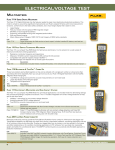
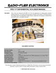
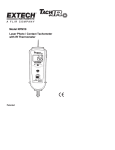
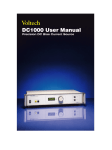
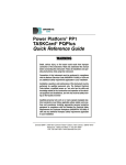
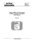
VOLTECHNOTES
Standby and
Low Power
Measurements
VPN 104-054/1
VOLTECHNOTES
LOW POWER MEASUREMENTS
Introduction
Voltech power analyzers provide a comprehensive range of accurate measuring instruments for voltage, current, and all power parameters. Each instrument features fully
isolated, floating inputs for the easy and safe connection of the ac power to be
measured. Accuracy of the measurements is guaranteed over the following broad
ranges:
Model
PM100CE
Current Range
Voltage Range
rms
peak
rms
peak
20mA to 20A
200A
2V to 700V
1000V
50mA to 30A
200A
0.5V to 1000V
1500V
PM300CE
PM3000ACE
The measuring ranges of the analyzers may be extended both higher and lower
using readily available transformers and other transducers. For high-power
measurements, current transformers such as the Voltech CL100, CT1000, and
CL3000 (100, 1000 and 3000A) are ideal for many applications.
2
Voltech high current transducers
© 2004 Voltech Instruments. All rights reserved.
LOW P OWER M EASUREMENTS
VOLTECHNOTES
This technical note discusses how Voltech power analyzers may be used to
measure the relatively small current and power quantities found when ac line
powered equipment is operating in a standby mode.
Technical Challenges
There is increasing legislative and consumer pressure to minimize the standby
power consumption of common domestic and office electrical equipment. For
example, USA Presidential Executive Order 13221 requests that government
agencies shall “purchase products that use no more than one watt in their standby
power consuming mode”.
It is, thus, important to product design and test engineers to have the ability to
accurately measure ac power below one watt. This can be more difficult than it
would first appear for two main reasons.
1.
Dynamic Range
If the range and accuracy of the measuring instrument and its current transducers are not carefully considered, the measurement may be inaccurate or
obscured by noise.
For example, a clamp-on power meter rated to 100A is used to measure 10mA. In
this case, the reading is 1/10000 full scale of the meter. The current clamp,
designed for 100A, will introduce very significant measurement errors and may
not register a current at all.
To make accurate low-power measurements, the current transducer should be
appropriate to the level of current being measured and matched to the abilities of
the power meter.
2.
Burst Mode Standby
The switching power supplies found inside most domestic, office and industrial
equipment will often draw greater than 1 Watt, just to supply their own control
circuits. To minimize consumption at no load, various techniques are applied that
shut down the power supply controller for intermittent periods. Terms used are
© 2004 Voltech Instruments. All rights reserved.
3
VOLTECHNOTES
LOW P OWER M EASUREMENTS
'burst mode' and 'skip cycle' amongst others.
The effect on the input is that intermittent bursts of current and power are drawn
from the line. Significant current may still be drawn in the 'dead' period. The bursts
are regular and repetitive but may vary with line voltage, load, etc. and are not
crystal-controlled.
Current (mA)
800
400
0
2
Time
4 (seconds)
-400
-800
When current and power is drawn in bursts like this from the ac supply, power
meters will attempt to track the variations and will often only provide a varying and
inconsistent power measurement that is not definitive.
Voltech Solution
1.
Dynamic Range
Voltech power analyzers are equipped with an external shunt input that may be
connected to any suitable external shunt or current transducer. By entering a scale
factor into the analyzer, the correct current and power quantities can then be
displayed and transferred over the communication interfaces.
Notice that it is not necessary to purchase an expensive, special model power
analyzer; the standard models are capable of measurements from micro-amps to
mega-amps as long as an appropriate transducer is used.
4
© 2004 Voltech Instruments. All rights reserved.
VOLTECHNOTES
LOW P OWER M EASUREMENTS
Example:
An office laser printer is designed to have a standby mode where less than 1W of
power is consumed. What value of external shunt should be used to make accurate measurements with a standard Voltech power analyzer?
Choosing an external shunt:
a) At 110V ac, the current will be:
1W / 110V = 9.09mA
(at a power factor of 1)
Let us say that the minimum current to be measured is 5mA, which allows some
margin for other products and voltages.
b) The minimum recommended external shunt voltage input of the PM3000ACE is
6.25mV. Minimum resistive shunt value is:
6.25mV / 5mA = 1.25Ω.
Ω.
Choose a readily available 0.1% tolerance resistor: 10Ω
c) Connect the analyzer to the equipment under test (EUT) as shown below.
A.C.
Supply
E.U.T.
10 Ω
!
Consult the product
user manual for safety
information.
Scaling =
10 Volts/Amp
A EXT
A LO
AHI
V LO
V HI
Voltech Power Analyzer
5
© 2004 Voltech Instruments. All rights reserved.
VOLTECHNOTES
LOW P OWER M EASUREMENTS
A Voltech breakout box may be used to simplify the power connections, if required.
d) Next, and on the front panel of the PM100 or PM3000ACE, select 'External
Shunt' as the current input and enter the scale factor. A 10 ohm resistor scales at
10 Volts / Amp for the PM100 and 800 for the PM3000ACE. Consult the product
user manual for details.
e) The power analyzer is now ready to make accurate low-current measurements.
A convenient way of connecting an external shunt resistor is to purchase a readymade assembly such as that shown below. For improved accuracy and frequency
response, non-inductive and four-terminal (Kelvin connection) shunts may be
used.
Precision Resistor Co., Inc.
www.precisionresistor.com
6
PRC shunt shown fitted to a PM100. Special channels are not required.
© 2004 Voltech Instruments. All rights reserved.
VOLTECHNOTES
LOW P OWER M EASUREMENTS
Clamp-on probes designed specifically for low-current measurements are also
available.
Chauvin-Arnoux E6N
• 5mA to 1.5A
• DC to 2kHz
• Scale factor: 1V / A
www.chauvin-arnoux.com
Note:
Consider also the maximum current that will be passed through the shunt or
transducer. When a resistive shunt is used, consider its current and power rating
(I2R) and fitting a fuse in series with the shunt. This will protect the shunt from
damage should an accidental over-current occur.
Voltech power analyzers are fitted with over-current devices which will protect
them from damage in the majority of circumstances.
2.
Burst-mode standby
To overcome the problems encountered in measuring the time-varying current
and power in a stable fashion, the power analyzer must make continuous
measurements at a high sample rate over an extended period of time and display
the averaged results. Watt-hour integration features may be used to do this, but
they are often processed at a lower sample rate and data (especially that related
to the dead period in between bursts) may be lost. (This is not the case with the
© 2004 Voltech Instruments. All rights reserved.
7
VOLTECHNOTES
LOW P OWER M EASUREMENTS
Voltech PM3000ACE).
On the Voltech PM100, a special long averaging mode is available which:
•
Samples at 200kHz to ensure no loss of data.
•
Continuously averages all results together to constantly update and display the
averaged measurements.
•
Allows the user to select an appropriate averaging time.
•
Displays all results, including volts, amps, watts and harmonics.
PM100 Example
An ac power supply is equipped with a low-power standby mode. In this mode,
current is drawn from the supply in 'bursts' that occur every 300ms or so. The waveform is shown below.
A measurement of the average input power is required to check the rating of the
Current (mA)
800
400
0
2
Time
4 (seconds)
-400
-800
power supply. With default settings, the PM100 makes measurements at high speed
and updates the display approximately every ½ second. With the waveform above,
8
the measurements are not stable, and the analyzer pauses while it auto-ranges inbe© 2004 Voltech Instruments. All rights reserved.
LOW P OWER M EASUREMENTS
VOLTECHNOTES
tween readings.
To make stable average measurements, follow this procedure:
1.
Measure the peak current.
In normal power-on mode, press the [A] key and then the [PEAK] key. Amps
peak will be displayed. In this example, the maximum reading was approximately
-750mA.
2.
Set up a fixed current range.
↵] until you see:
Press [MENU], [1] and then [↵
MANUAL A RANGE
X
>√<
and then enter the nominal peak current, ignoring the (-) sign:
PEAK CURRENT
>0.750<
3.
Now set up long averaging in [MENU], [2].
LONG AVERAGING
X
>√<
The averaging time should include several cycles of operation of the equipment.
Equipment Cycle Time
Example
Long Averaging Time
< 1 sec
Power supply in low power
10 sec
standby mode.
1 - 10 sec
Signs, message boards,
100 sec
oscillating fan.
10 - 60 sec
Soldering iron.
300 sec
> 60 sec
Washing machine.
300 sec + Integrator
9
© 2004 Voltech Instruments. All rights reserved.
VOLTECHNOTES
LOW P OWER M EASUREMENTS
In this case, the power supply current seems to vary over a two-second period.
Choose 20 seconds for the averaging time. This can be increased later, if the
measurements are not stable.
AVERAGING TIME
>20.0<
Press [MENU] again, and the analyzer will now begin to make measurements. The
red PROG LED will flash to indicate that the PM100 is in long averaging mode.
All measurements are stable, reliable, accurate and continuously updated.
Conclusion
1)
Accurate, stable and reliable measurements of electrical equipment that is
operating in a standby mode differs from normal power measurements in two
ways:
a) The low current of typically less than 10mA may be below the specified
operating range of the analyzer. As a result, measurements will be
inaccurate or even totally obscured by noise.
b) The current may be drawn in bursts, and that requires specific measurement
techniques to provide reliable measurements.
2)
The low current range of Voltech power analyzers may be extended by using
an appropriate current transducer. It is not necessary to purchase special
power analyzer models to measure low current and power.
3)
The long averaging and integration techniques of Voltech power analyzers may
be used to provide burst power measurements that are accurate, stable and
repeatable.
10
© 2004 Voltech Instruments. All rights reserved.
LOW P OWER M EASUREMENTS
VOLTECHNOTES
References
1. Voltech Technical Note “Single Shunt Technology“ (item number 104-114)
2. Voltech Technical Note “Kelvin Connections“ (item number 104-104)
3. Voltech Technical Note “Back to Basics: AC Theory“ (item number 104-109)
4. PM100/300 User Manual (item number 98-052)
5. EU Energy Efficiency Initiative (http://energyefficiency.jrc.cec.eu.int/)
All Voltech items are available free of charge from your Voltech supplier or from
our website at www.voltech.com
11
© 2004 Voltech Instruments. All rights reserved.
VOLTECHNOTES
Voltech Instruments Ltd.
148 Sixth Street
Harwell International Business Centre
Didcot, Oxon OX11 0RA, UK
Telephone: +44 (0) 1235 834555
Facsimile: +44 (0) 1235 835016
E-mail: [email protected]
Voltech Instruments Inc.
11637 Kelly Road, Suite 306
Fort Myers, FL 33908, USA
Telephone: +1 239 437 0494
Facsimile: +1 239 437 3841
E-mail: [email protected]
www.voltech.com
Note: While every care has been taken in compiling the information for this publication, Voltech Instruments cannot accept legal liability for any inaccuracies. Voltech Instruments reserves the right to alter product specifications without notice and whenever necessary
to ensure optimum performance from its product range.
VPN 104-054/1