1
Published by Dranetz-BMI
1000 New Durham Road
Edison, NJ 08818-4019 USA
Telephone: 1-800-372-6832 or 732-287-3680
Fax: 732-248-1834
Web site: www.dranetz-bmi.com
Copyright © 2002 Dranetz-BMI
All rights reserved.
No part of this book may be reproduced, stored in a retrieval
system, or transcribed in any form or by any means—electronic,
mechanical, photocopying, recording, or otherwise—without
prior written permission from the publisher, Dranetz-BMI,
Edison, NJ 08818-4019.
Printed in the United States of America.
P/N 899103
March 2002
Safety Summary
Definitions
WARNING statements inform the user that certain conditions or
practices could result in loss of life or physical harm.
CAUTION statements identify conditions or practices that could
harm the Power Platform, its data, other equipment, or property.
NOTE statements call attention to specific information.
Symbols
The following International Electrotechnical Commission (IEC)
symbols are marked on the top and rear panel in the immediate
vicinity of the referenced terminal or device:
Caution, refer to accompanying documents
(this guide).
Alternating current (ac) operation of the
terminal or device.
Direct current (DC) operation of the
terminal or device.
Protective conductor terminal.
Power Platform-PQ Plus Quick Reference Guide
iii
Warranty
Dranetz-BMI warrants that the Power Platform will be free from defects in workmanship and
materials for a period of one year from the date of purchase. Dranetz-BMI will, without charge,
replace or repair, at its option, any warranted product returned to the Dranetz-BMI factory service
department.
Dranetz-BMI shall not be held liable for any consequential damages, including without limitation,
damages resulting from loss of use, or damages resulting from the use or misuse of this product.
Some states do not allow limitations of incidental or consequential damages, so the above limitation or exclusion may not apply to you.
This warranty gives you specific rights and you may also have rights which vary from state to
state.
Exclusions: This warranty does not apply in the event of misuse or abuse of the product or as a
result of unauthorized repairs or alterations.
Need Help?
How to Contact Dranetz-BMI
Regardless of your location, Dranetz-BMI sales and product support are within easy reach through
an established network of representatives and distributors worldwide.
For Sales, Technical Support, or the name of a Dranetz-BMI Sales Representative in your area,
call:
1-800-372-6832 or 732-287-3680
Fax: 732-248-1834
Web site: www.dranetz-bmi.com
iv
Power Platform-PQ Plus Quick Reference Guide
Table of Contents
Preface
Safety Summary . . . . . . . . . . . . . . . . . . . . . . . . . . . . . . . . . . . . . . . . . .iii
Warranty . . . . . . . . . . . . . . . . . . . . . . . . . . . . . . . . . . . . . . . . . . . . . . . .iv
Need Help? . . . . . . . . . . . . . . . . . . . . . . . . . . . . . . . . . . . . . . . . . . . . . .iv
The Impatient’s Guide to
Power Monitoring Procedures . . . . . . . . . . . . . . . . . . . . . . . . . . . . . . . . . .1
Chapter 1 Introduction & General Description . . . . . . . . . . . . . . . . . . . . .3
Power Platform PP1 and TASKCard PQPlus . . . . . . . . . . . . . . . . . . . . .3
Unpacking the Unit . . . . . . . . . . . . . . . . . . . . . . . . . . . . . . . . . . . . . . . .3
Front Panel . . . . . . . . . . . . . . . . . . . . . . . . . . . . . . . . . . . . . . . . . . . . . . .4
Rear Panel . . . . . . . . . . . . . . . . . . . . . . . . . . . . . . . . . . . . . . . . . . . . . . .6
Positioning the Unit . . . . . . . . . . . . . . . . . . . . . . . . . . . . . . . . . . . . . . . .8
Chapter 2 Cable Connections . . . . . . . . . . . . . . . . . . . . . . . . . . . . . . . . . . .9
Warning and Safety Precautions . . . . . . . . . . . . . . . . . . . . . . . . . . . . . . .9
Connecting a Voltage Probe . . . . . . . . . . . . . . . . . . . . . . . . . . . . . . . . .10
Connecting to a Potential Transformer . . . . . . . . . . . . . . . . . . . . . . . . .14
Connecting a Current Probe . . . . . . . . . . . . . . . . . . . . . . . . . . . . . . . . .15
Connecting to a Current Transformer . . . . . . . . . . . . . . . . . . . . . . . . . .19
Connecting to an Isolated Current Transformer . . . . . . . . . . . . . . . . . . .20
Chapter 3 Easy Start Setup . . . . . . . . . . . . . . . . . . . . . . . . . . . . . . . . . . . .25
Turning the Unit On . . . . . . . . . . . . . . . . . . . . . . . . . . . . . . . . . . . . . . .25
Viewing Scope Mode . . . . . . . . . . . . . . . . . . . . . . . . . . . . . . . . . . . . . .27
Viewing Meter Mode . . . . . . . . . . . . . . . . . . . . . . . . . . . . . . . . . . . . . .28
Using Easy Start . . . . . . . . . . . . . . . . . . . . . . . . . . . . . . . . . . . . . . . . . .30
Power Platform-PQ Plus Quick Reference Guide
v
Table of Contents
Chapter 4 Circuit Types & Predefined Setups . . . . . . . . . . . . . . . . . . . . .35
Circuit Connection Diagrams, Phasor Diagrams, and the
Predefined Setups Corresponding to each Circuit Type . . . . . . . . . . . . .35
Warning and Safety Precautions . . . . . . . . . . . . . . . . . . . . . . . . . .36
Single Phase . . . . . . . . . . . . . . . . . . . . . . . . . . . . . . . . . . . . . . . .37
Split Phase . . . . . . . . . . . . . . . . . . . . . . . . . . . . . . . . . . . . . . . . . .40
Four Wire Wye . . . . . . . . . . . . . . . . . . . . . . . . . . . . . . . . . . . . . . .42
Floating Delta . . . . . . . . . . . . . . . . . . . . . . . . . . . . . . . . . . . . . . .45
Delta, One Leg Grounded . . . . . . . . . . . . . . . . . . . . . . . . . . . . . .48
Open Leg Delta . . . . . . . . . . . . . . . . . . . . . . . . . . . . . . . . . . . . . .49
High Leg Delta . . . . . . . . . . . . . . . . . . . . . . . . . . . . . . . . . . . . . .50
Selecting a Circuit Type . . . . . . . . . . . . . . . . . . . . . . . . . . . . . . . . . . . .51
Verifying Voltage and Current Connections . . . . . . . . . . . . . . . . . . . . .52
Selecting and Activating a Setup . . . . . . . . . . . . . . . . . . . . . . . . . . . . . .54
Editing Parameter Thresholds . . . . . . . . . . . . . . . . . . . . . . . . . . . . . . . .56
Triggerable Parameters for Power Platform Series . . . . . . . . . . . . . . . .57
Chapter 5 Memory Card Operations . . . . . . . . . . . . . . . . . . . . . . . . . . . .61
Entering a Site/File Name . . . . . . . . . . . . . . . . . . . . . . . . . . . . . . . . . . .61
Setting Memory Storage Mode . . . . . . . . . . . . . . . . . . . . . . . . . . . . . . .62
Setting Auto-transfer to Memory Card . . . . . . . . . . . . . . . . . . . . . . . . .65
List of Accessories . . . . . . . . . . . . . . . . . . . . . . . . . . . . . . . . . . . . . . . . . . .65
Standard Accessories . . . . . . . . . . . . . . . . . . . . . . . . . . . . . . . . . . . . . .65
Optional Accessories . . . . . . . . . . . . . . . . . . . . . . . . . . . . . . . . . . . . . .65
vi
Power Platform-PQ Plus Quick Reference Guide
Impatient’s Guide to Power Monitoring
Power Platform Monitoring Procedure
This outline is not meant to be all-inclusive and does not cover all aspects of
monitoring setup. It is meant to make sure that the basic procedural issues on
power monitoring are explained and understood to minimize the learning curve.
The procedures below are discussed in detail in the next chapters.
Starting A New Session:
1. Reset To Factory Configuration [Memory Functions]
NOTE: Skip this step if you wish to maintain Input Configurations and
Thresholds.
2. Make sure unit is set to Auto-transfer Disabled [Memory Functions]
3. Make sure Monitoring is Off [Setup Menu]
4. Clear Event Memory [Memory Functions]
5. Insert Memory Card (If you are using one)
6. Format Memory Card [Memory Card Functions]
NOTE: All data on card will be lost. Save important data on computer hard
disk.
7. Set desired Site Name [Set Programmable Features]
8. Set Memory Mode: [Memory Functions]
Fill and Stop: Monitoring will stop when Internal Memory fills up. Does not
take advantage of Memory Card.
Overwrite: Internal memory will overwrite old data as it fills. If auto-transfer
is enabled, card will fill until full and then stop. Card will not overwrite.
Internal memory will continue to overwrite when card is full.
NOTE: Overwrite is recommended with Memory Card use.
9. Run Easy Start [Setup Menu]
You will need to know a) circuit type, b) the nominal measurement voltage,
c) which current probe you are using, and d) nominal current.
NOTE: PT and CT setup are beyond the scope here, refer to User’s Manual.
Power Platform-PQ Plus Quick Reference Guide
1
Impatient’s Guide to Power Monitoring
10. Set Waveform Capture [Advanced Setup Options][Set Thresholds]
Make sure Waveform Capture is ON-ON for all the parameters important to
you. At least V Hi, V Lo, I Hi, I Lo, V Trans, I Trans.
11. Set Waveform Capture for Timed Events [Advanced Setup Options] [Set
Input Configurations]
This is recommended for problem analysis but will consume memory.
12. Enable Auto-transfer to Memory Card [Memory Functions]
This may take several minutes with a 4 meg card. The unit is setting up the
auto transfer file on the memory card called {sitename}.mdb. Available
space will read minimal even though the card is empty.
NOTE: NEVER change the site name after enabling auto-transfer. You will
not collect data.
13. Check Meter Mode and make sure the measurements make sense.
14. Check the Phasor Diagram and make sure it matches the diagrams shown in
this Quick Reference Guide for your specific circuit type.
15. Clear Event Memory
16. Turn Monitoring on
17. Check View Data after 15 to 30 minutes
Check Time Plots
View Events by Number. If you see a number of events of the same type
you have either solved the power problem or you may need to adjust the
Threshold.
2
Power Platform-PQ Plus Quick Reference Guide
Introduction & General Description 1
Power Platform PP1 and TASKCard PQPlus
The Dranetz-BMI Power Platform introduces a new concept in power monitoring equipment by allowing you to change the type of monitoring the unit does
by changing a TASKCard.
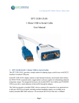
A TASKCard is a removable memory card that is installed in the rear panel of
the Power Platform and contains an operating system that is designed for a
specific application (task). The PQPlus TASKCard, shown below, changes the
Power Platform to a power quality monitor so that it can record sags, swells,
transients, outages, plus demand, energy and harmonics.
Unpacking the Unit
Unpack the Power Platform from the carton as follows:
1. Remove any remaining literature inside the top of the carton.
2. Carefully remove the Power Platform from its shipping carton.
3. Remove all accessories inside the carton. Check that the Standard
Accessories are included. Pages 65-66 list the Part Number and Description of
the Standard and Optional Accessories.
4. Place all of the shipping materials back into the carton, close its flaps, and
store it away. DO NOT throw away the carton and packing materials. Save the
carton and packing materials in case you have to return the Power Platform to
Dranetz-BMI for maintenance, repair, or calibration.
Power Platform-PQ Plus Quick Reference Guide
3
1 Introduction & General Description
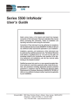
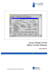
Front Panel
The front panel, including screen, keypad, printer, and memory card is
protected by a locking, flip-top type display housing. The padded bail handle
can be used as a carrying handle or as a means to position the unit.
1
4
Liquid Crystal Display (LCD) Provides 2 3/4 x 4 1/2 inch (5 x 10 cm)
display consisting of 240 by 128 pixels (dots) of text and graphic information. Has electroluminescent (EL) back lighting for low light level viewing.
Power Platform-PQ Plus Quick Reference Guide
Introduction & General Description 1
2
Numeric Keypad Consists of keyboard keys 0 thru 9 and decimal point (.).
Permits menu selection and numerical data entry.
3
Question Mark Key Provides selection of User Guide to display help
screens with reference to screen displayed at any time.
4
Contrast Control Provides contrast range control for LCD viewing.
5
Paper Feed Controls paper feed and take up to advance the paper
uniformly across window from right to left.
6
Paper Take-up Controls paper slack.
7
Data Card Release Ejects data (memory) card.
8
Data Card Holder Holds and connects data (memory) card to internal
circuitry.
*9 Thermal Paper Printout High-resolution thermal print of real-time data
and report information.
10 Data Card Busy LED Yellow LED indicates data (memory) card is being
accessed.
*11 Run/Load Printhead Control Lever in left position for normal run
operation. Lever in right position lifts printhead from paper for loading or
paper pulling.
12 Keylock Secures front panel in locked shut position.
*13 Finger Groove Access to grasp and pull paper out for viewing.
NOTE: Printhead control must be in LOAD position before paper is pulled.
*14 Printer Door Latch Moves to right to unlock printer door.
15 Function Keys Used to select options that appear on bottom of screen.
Function selected varies with screen displayed.
*Part of PP1 with printer.
Power Platform-PQ Plus Quick Reference Guide
5
1 Introduction & General Description
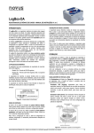
Rear Panel
The rear panel contains the input and output connectors including the slot for
the TASKCard. See Chapter 2 for rear panel cable connections.
Dranetz Model PP1
8600-17
6
1
CHANNEL A, + Differential Voltage Input Connector; color red.
2
CHANNEL A, - Differential Voltage Input Connector; color white.
3
CHANNEL A CURRENT PROBE Input Connector.
4
CHANNEL B, + Differential Voltage Input Connector; color yellow.
5
CHANNEL B, - Differential Voltage Input Connector; color white.
6
CHANNEL B CURRENT PROBE Input Connector.
7
CHANNEL C, + Differential Voltage Input Connector; color blue.
Power Platform-PQ Plus Quick Reference Guide
Introduction & General Description 1
8
CHANNEL C, - Differential Voltage Input Connector; color white.
9
CHANNEL C CURRENT PROBE Input Connector.
10 CHANNEL D, + Differential Voltage Input Connector; color grey.
11 CHANNEL D, - Differential Voltage Input Connector; color white.
12 CHANNEL D, CURRENT PROBE Input Connector.
13 SAFETY GROUND Connector; color green.
14 DIGITAL INPUTS, 12-48 VDC. Four channels of digital signal inputs.
15 PARALLEL PORT, Parallel data port.
16 On/Off Switch. 1 = ON, 0 = OFF.
17 Fuseholder (Main Power). SLOW BLOW 250 VAC T1.25A 5x20 mm.
18 POWER REQUIRED, 90-130 VAC 180-250 VAC, 47-450 Hz, 100 W
MAX. Input power plug.
19 RS232D DCE, Serial data port.
20 Internal/ External battery fuse. SLOW BLOW, 250 VAC T6.3A
5x20 mm.
21 10-16VDC, External DC voltage source input.
22 TASK CARD, connector slot.
TASKCard Protective Cover, mounted with screws after TASKCard is
installed. (Not shown)
23 RELAY CONTACTS, 120 VAC AT 1A MAX, 30 VDC AT 1A MAX.
Four sets of relay contacts.
Power Platform-PQ Plus Quick Reference Guide
7
1 Introduction & General Description
Positioning the Unit
Handle releases, in the pivots of the handles, must be pressed inwards together
to unlock the handles. Once released, the handles can be positioned in three
positions: one for carrying the unit, and two for viewing the display at 15 or 45
degrees. At each position the handles will lock and must be released again to be
repositioned.
Handle release
location and
carrying position
8600-53
45o Viewing Position
8600-54
15o Viewing Position
8600-55
8
Power Platform-PQ Plus Quick Reference Guide
Cable Connections 2
This chapter displays the connection of the various voltage and current devices
that can be used when making measurements. Before working on the cable
connections, follow the Warning advisory and all Safety Precautions below.
WARNING
Death, serious injury, or fire hazard could result from improper
connection of this instrument. Read and understand this manual
before connecting this instrument. Follow all installation and
operating instructions while using this instrument.
Connection of this instrument must be performed in compliance
with the National Electrical Code (ANSI/NFPA 70-2002) of USA
and any additional safety requirements applicable to your installation.
Installation, operation, and maintenance of this instrument must
be performed by qualified personnel only. The National Electrical
Code defines a qualified person as “one familiar with the construction and operation of the equipment and the hazards
involved.”
Safety Precautions
· Connect the green safety (earth) ground first, before making any other
connections.
· When connecting to electric circuits or pulse initiating equipment, open their
related breakers. DO NOT install any connection of the instrument on live
power lines.
· Connections must be made to the instrument first, then connect to the circuit
to be monitored.
· Wear proper Personal Protective Equipment, including safety glasses and
insulated gloves when making connections to power circuits.
· Hands, shoes and floor must be dry when making any connection to a power
line.
· Make sure the unit is turned OFF before connecting probes to the rear panel.
· Before each use, inspect all cables for breaks or cracks in the insulation.
Replace immediately if defective.
Power Platform-PQ Plus Quick Reference Guide
9
2 Cable Connections
Connecting a Voltage Probe
The voltage measurement probe is made up of eight, 8-foot channel measurement cable assemblies.
Measurement Cable Set
Part Number: All items below are packed and labeled as Measurement Cable
Set with Part Number 115815-G1 (Domestic), 115815-G2 (Euro), or 115815G3 (UK). The voltage probes, jumpers, and power cord are provided as
standard accessories and are stored in a cable pallet as part of the measurement
cable set.
Voltage Safety Clips. Each clip comes with a detachable, crocodile jaw, safety
clip assembly. The safety clip assemblies are red (+) and black (-) for each of
the four channels.
Probe Cables. One probe assembly each of red (channel A), yellow (channel
B), and blue (channel C) and five each of black are provided.
Jumpers. Four 1-foot blue or black jumpers for input connector jumpering.
Shielded power cord.
See figure next page. A pallet for storage of the cables and the input power
cord are included in the contents of the measurement cable set but are not
shown in the figure.
Voltage Rating
Direct connection of all voltage probes for measurement are rated at 600 Vrms
max. For measuring voltages greater than 600 Vrms Potential Transformers
(PTs) must be used.
10
Power Platform-PQ Plus Quick Reference Guide
Cable Connections 2
Voltage Measurement Cable Set
8600-28
Part Number: 115815-G1 (Domestic)
115815-G2 (Euro)
115815-G3 (UK)
NOTE: Pallet and Input power cable not shown.
Power Platform-PQ Plus Quick Reference Guide
11
2 Cable Connections
Connection Guidelines
Follow these guidelines when making voltage connections.
· Refer to the measurement test set figure for color coding of probes that
connect to input channel connectors A, B, C, and D.
· Each channel input has plus (+) and minus (-) differential inputs of 60 to
600Vrms max. Unused voltage channel differential inputs must be jumpered
together using the blue or black jumpers provided.
· Channel D has an additional low voltage range of 0 to 60 Vrms max. for low
voltage measurements.
Sample Single Phase Connection
The following figure shows a voltage connection to a single phase circuit for
channel A. Jumpers are used to connect the differential inputs of channels B, C,
and D together as shown to prevent erroneous data. The green cable is always
connected to a secure ground (earth) connection as a safety ground.
LINE
LOAD
RED
LOAD
RED
A
NEUTRAL
RETURN
BLK
SOURCE
BLK
GRN
JUMPER
JUMPER
JUMPER
SAFETY
GROUND
8600-18
12
Power Platform-PQ Plus Quick Reference Guide
Cable Connections 2
Sample Neutral to Ground Connection
The following figure shows a voltage connection using channel D as a differential input for a single phase connection. Connections are identical for split
phase, delta, and wye configurations. One probe connects the source neutral
line to the D+ input. Another probe connects the safety ground to the D- input.
Any channel input may be used to perform this measurement but Channel D is
usually used because it provides a low voltage range of 0 to 60 Vrms.
LINE
LOAD
RETURN
NEUTRAL
BLK
SOURCE
BLK
GROUND
BLK
BLK
GRN
SAFETY
GROUND
8600-19
Power Platform-PQ Plus Quick Reference Guide
13
2 Cable Connections
Connecting to a Potential Transformer
A potential transformer (PT), also referred to as a voltage instrument
transformer, provides the necessary step-down ratio to reduce the high voltage
of circuits above 600 Vrms to a level for safe measurement. A PT also provides
isolation and proper connections for instrument attachment.
WARNING: Refer to the manufacturer’s instructions for exact information on
probe connection of the PT for voltage monitoring. Do not exceed 600 Vrms
input to the PP1 Voltage inputs. Potential transformers are not manufactured
by Dranetz-BMI.
Connection Guidelines
PTs are usually fixed in position and require that the voltage probe(s) be
connected to their terminal connections. Follow these steps to connect voltage
probes to a potential transformer.
1. Turn off power to the PT.
2. Connect the green ground connector to the Safety Ground connector on the
rear panel of the Power Platform.
3. Connect the green ground connector to a solid ground point at or near the PT
in accordance with the PT manufacturer’s instructions.
4. Connect the colored voltage probes to the PT’s connections in accordance
with the manufacturer’s instructions.
5. Connect the colored voltage probes to the channel inputs designated for
monitoring.
6. Turn on power to the PT.
14
Power Platform-PQ Plus Quick Reference Guide
Cable Connections 2
Connecting a Current Probe
Several types of current probes (clamp-on current transformers) are available as
optional accessories. Dranetz current probes are available in various sizes.
Dranetz Current probes
CT10
CT150
CT300
CT1000
CT3000
8600-21
WARNING: When using either the CT-10 or CT-150 current probe, DO NOT
connect the probe jaws around a non-insulated wire. These probes are to be
used to monitor current of insulated wire only.
Power Platform-PQ Plus Quick Reference Guide
15
2 Cable Connections
Specifications
The following table lists the operating specifications for all optional Dranetz
current probes.
CT150
CT300
CT1000
CT3000
Current Range 1 to 10
for Amplitude
Accuracy
(Arms) of 0.5%
CT10
3 to 125
10 to 300
50 to 1000
200 to 3000
Current Range
for Phase
Accuracy of
0.2° (Arms) at
Calibration
Point ( )
2 to 10
(5)
5 to 125
(30)
15 to 300
(200)
100 to 1000 300 to 3000
(200)
(300)
Frequency
Range (Hz)
45 to
10,000
45 to
10,000
15 to
10,000
30 to
50,000
Impulse Width
Typically -3dB at 1 µsecµsec at one-half sine wave.
Output Signal
of 3 Vrms at
10 Arms 150 Arms 300 Arms
Maximum
0.47"
Conductor Size (12mm)
16
0.47"
(12mm)
2.13"
(54mm)
30 to
5000
1000 Arms
3000 Arms
2.17"
(55mm)
2.56"
(65mm)
or
1.97" x 5.3"
(50 x 135 mm)
or
2.56" x 3.94"
(65 x 100 mm)
Power Platform-PQ Plus Quick Reference Guide
Cable Connections 2
Wire Marker Kit
The wire marker kit, supplied as a standard accessory, helps you identify which
current probe is connected to each current channel input. This kit, Part Number
155520, contains adhesive backed color-coded marker labels to attach to the
probe handle and the plug end of the probe. Use red label for channel A, yellow
for B, and blue for C. Channel D is left unmarked. See figure below for proper
wire marker placement.
Wire marker
placement
8600-62.pcx
Connection Guidelines
Each probe has a polarized plug to fit any one of the four current input connectors (A, B, C, or D) on the rear panel of the Power Platform.
An arrow marking on the handle is a guide to ensure that you position the
probe with the arrow pointing towards the load. Correct position of the probe is
necessary for correct power measurements.
Follow these guidelines when making current connections.
· Position the probe with the arrow on the handle facing the load.
· For greatest accuracy, use a probe that is rated at no more than twice the
nominal value you expect to measure.
See figure next page showing how to connect a current probe to channel A for
current monitoring of a single phase line.
Power Platform-PQ Plus Quick Reference Guide
17
2 Cable Connections
Sample Single Phase Connection
The current probe may be connected to the return line if desired to measure the
return current when checking for load current leakage, loop current relationships, etc.
LINE
LOAD
LOAD
RETURN
NEUTRAL
SOURCE
RED
GRN
SAFETY
GROUND
8600-20
NOTE: The connection shown above is not recommended without a voltage
connection to ensure frequency synchronization.
18
Power Platform-PQ Plus Quick Reference Guide
Cable Connections 2
Connecting to a Current Transformer
Current transformers, also known as instrument transformers, reduce high level
currents to low level currents so they can be safely monitored. These devices
are similar to PTs used for voltage measurements in that both reduce values for
safe measurement. The reduction, or step-down ratio, is stated as a scale factor
that is used by the PP1-PQPlus to step-up the measured value to its original
value.
Safety Precautions
The following safety precautions apply to current transformer (CT) connections
in addition to the Safety Precautions stated on page 9.
· Never energize a CT with the secondary open.
· Never disconnect the secondary of a CT with primary energized.
WARNING: Refer to the manufacturer’s instructions related to the CT for
exact information on connections for current monitoring. Do not exceed
manufacturer’s ratings. Potential transformers are not manufactured by
Dranetz-BMI.
Types of CTs
There are single-phase CTs and polyphase CTs dependent on the source
transformer used. Current reduction ratios vary widely and are also dependent
on the source transformer used. Rating plates attached to the CT provide
information as to the ratio and current limitations.
Power Platform-PQ Plus Quick Reference Guide
19
2 Cable Connections
Connecting to an Isolated Current Transformer (ISO)
Low current monitoring devices made by Dranetz are called isolated current
transformers or ISO boxes for short. They are typically used to monitor the
output of existing CTs. Dranetz makes two types of ISO boxes; one model
(ISO-1A) monitors up to 1 amp rms of current maximum, the other model
(ISO-5) up to 5 amps rms maximum. Both are available as optional accessories.
Safety Precautions
The following safety precautions apply to current transformer (CT) connections
in addition to the Safety Precautions stated on page 9.
· Never energize a CT with the secondary open.
· Never disconnect the secondary of a CT with primary energized.
WARNING: Physical injury or equipment damage could result if ISO boxes
are improperly connected. Do not connect an ISO box between two
conductors which are at different voltage potentials.
Connection Guidelines
ISO boxes can be used in a number of ways. These methods include:
· connecting them to the secondary of CTs for metering by the PP1-PQPlus
· inserting them in series with the load current to measure low current values
· connecting them to a non-Dranetz clamp-on current transformer and using
that CT to monitor current with the PP1-PQPlus.
See figures displayed in the next pages showing the different ways to connect
ISO boxes.
20
Power Platform-PQ Plus Quick Reference Guide
Cable Connections 2
Sample ISO box connection to a current transformer
The figure below shows an ISO box connected from Channel B current input to
a permanently installed CT. Polarities of the ISO box and CT are kept in-phase
by matching markings. Scale factors of both devices must be multiplied
together to get the resultant scale factor.
8600-24
Power Platform-PQ Plus Quick Reference Guide
21
2 Cable Connections
Sample ISO box in-line connection
The figure below shows the ISO box connected in series with the load of a
single-phase line. The connection is made with the X1 terminal connected to
the source input line and X2 connected to the load line. The scale factor is that
of the ISO box only.
8600-25
22
Power Platform-PQ Plus Quick Reference Guide
Cable Connections 2
Sample ISO box connecting to a non-Dranetz current probe
The figure below shows the ISO box connected to a non-Dranetz clamp-on
current transformer. In this case the scale factor is the product of the ISO box
and the CT. Refer to manufacturer’s literature to determine the CT scale factor.
WARNING: Refer to the manufacturer’s instructions related to the CT for
exact information for connections for current monitoring. Do not exceed
manufacturer’s ratings.
8600-26
Power Platform-PQ Plus Quick Reference Guide
23
2 Cable Connections
This page intentionally left blank.
24
Power Platform-PQ Plus Quick Reference Guide
Easy Start Setup 3
This chapter provides information on using the Easy Start function of the
Power Platform-PQPlus. Easy Start is a series of screens that prompts you for
information about the circuit you will be monitoring. The PP1-PQPlus then
automatically turns on the correct channels, sets the monitoring thresholds, and
chooses the types of reports that it will print out.
Turning the Unit On
Follow these steps to turn on the Power Platform.
1. Plug unit into an ac power source.
2. Verify that the PQPlus TASKCard is inserted into the slot on the rear panel.
3. Turn on the unit.
Result: If the TASKCard is inserted correctly, the unit will perform
internal diagnostics, momentarily display the message “TASKCard
Found, Loading PQPlus Vxx”, then display the scope mode screen
shown below.
NOTE: If the TASKCard is not inserted correctly, or if the TASKCard
is corrupted, an error message will be displayed indicating TASKCard
or downloading failure. See next page for a list of the error message
types and what to do next.
4. Pressing PRINT will print a copy of the empty display as shown.
Power Platform-PQ Plus Quick Reference Guide
25
3 Easy Start Setup
Possible TASKCard Error Messages
The following describes the possible error messages when loading the
TASKCard and the corrective action to take for each.
26
Error Message
TASKCard Not Found.
Booting From ROM.
What to Do Next
TASKCard may not be installed or
is installed incorrectly. Turn off
power and recheck TASKCard
installation.
Corrupt TASKCard.
Booting from ROM.
A TASKCard was found but it was
not recognized as a valid
TASKCard. Turn off power and
recheck TASKCard. If the
TASKCard is properly inserted,
there may be a problem, notify
Dranetz.
WARNING:
The TASKCard found:
(now installed) Is the unit
different than last used:
(previous TASKCard)
CHANGING TASKCARDS
MAY ERASE MEMORY!
Press any key to continue or turn
off and reinstall the last
TASKCard used.
Any of the following:
I/O Processor - Download Failed
ACP Processor - Download Failed
I/O Processor - Will Not Respond
ACP Processor - Will Not Respond
TASKCard download problem.
Notify Dranetz for further
assistance.
Power Platform-PQ Plus Quick Reference Guide
Easy Start Setup 3
Viewing Scope Mode
Scope Mode allows you to view real-time voltage and current waveforms for
up to four channels. To display the screen below, from Main Menu, select item
2, Scope Mode.
How to Select Channels for display
1. In Scope Mode display, press SELECT CHAN.
Result: The following screen will appear.
2. Press VOLTS ON/OFF to toggle selected channel On or Off for voltage
waveform display.
3. Press AMPS ON/OFF to toggle selected channel On or Off for current
waveform display.
4. Press NEXT CHAN to select channels A, B, C, and/or D.
5. Repeat steps 2 through 4 for each channel to be selected.
6. Press EXIT to display the channels selected.
Power Platform-PQ Plus Quick Reference Guide
27
3 Easy Start Setup
Viewing Meter Mode
In addition to monitoring for power disturbances, the PP1-PQPlus is a true
RMS voltmeter and true RMS clamp-on ammeter. Voltage and current measurements, along with all other calculated parameters, are displayed on the Meter
Mode screens. The PP1-PQPlus also functions as a phase angle meter,
wattmeter, VAR meter, PF meter, and frequency meter.
In meter mode, you can select any one channel for viewing with all parameters
displayed, or you can select an individual parameter for viewing with all channels displayed.
Channels that can be viewed
Channels A, B, C, or D can be viewed individually or collectively for single
phase monitoring. For Delta mode the sequence is: A-B, B-C, C-A, D, and
ABC.
Available Parameters
The following table lists the parameters that can be viewed in meter mode.
Parameter
Symbol
Volts RMS
V
Amps RMS
I
Watts
W
Volt-amps
VA
Volt-amps Reactive
VAR
Power Factor (True)
PF
Voltage Frequency
Hz
Voltage Unbalance
Vunb%
Volts, Total Harmonic Distortion
Vthd
Amps, Total Harmonic Distortion
Ithd
Current Crest Factor
Icf
k-Factor
KF
Demand
Dmd
Energy
WHR
Volts, Harmonic Number
V harm n
Amps, Harmonic Number
I harm n
28
Power Platform-PQ Plus Quick Reference Guide
Easy Start Setup 3
How to View Meter Mode displays
1. In Scope Mode display, press METER MODE to view the Meter Mode
Menu below.
2. Press 1 if one channel and all parameters are to be viewed.
Press NEXT CHAN to display next channel parameters.
Press NEXT GROUP to display the next group of data for the
channel selected.
3. Press 2 if all channels and one parameter are to be viewed.
(Continue next page)
Power Platform-PQ Plus Quick Reference Guide
29
3 Easy Start Setup
(Cont. - How to view Meter Mode displays)
4. Press 3 for the all channels, all parameters display.
Using Easy Start
The Easy Start function prompts you for information about the circuit you want
to monitor and then automatically sets up the Power Platform for monitoring
and reporting.
CAUTION: The Easy Start process will change previously programmed
instrument settings and configurations. Monitoring is also shut down during
Easy Start programming.
Follow these steps if you are using the Easy Start function of the PP1-PQPlus.
1. From the scope mode screen, press EASY START.
Result: The following screen will appear.
2. Is the unit connected to a circuit and collecting data?
If yes, press CANCEL and save data to a memory card before
proceeding.
If no, press CONTINUE and enter the required information as you
proceed through the Easy Start screens.
30
Power Platform-PQ Plus Quick Reference Guide
Easy Start Setup 3
Monitoring Combinations
The following table lists the input channels that will be turned on based on the
circuit type that you choose, monitor current setting, and neutral to ground
setting.
Monitor
Current
ON
Neutral to
Ground
ON
Single
Phase
Va, Vd,
Ia, Id
Split
Phase
Va, Vb, Vd,
Ia, Ib, Id
3 Phase
(Wye or Delta)
Va, Vb, Vc, Vd,
Ia, Ib, Ic, Id
ON
OFF
Va, Ia
Va, Vb,
Ia, Ib
Va, Vb, Vc, Ia,
Ib, Ic
OFF
ON
Va, Vd
Va, Vb, Vd
Va, Vb, Vc, Vd
OFF
OFF
Va
Va, Vb
Va, Vb, Vc
Parameter Thresholds
The following table lists the settings for the parameters in the Easy Start setup.
All other parameters are turned off.
Parameter
V HIGH RMS
V LOW RMS
V TRANSIENT
V THD %
V FREQ
I HIGH RMS
PF LOW LIM
V SENS OUT LIM
V TRANS % RAISED
I TRANS % RAISED
Setting
+ 10%* from nominal
- 10%* from nominal
150% of nominal
10%
2.0 Hz
+ 10%* from nominal
0.85
5
50%
50%
* This number is the default percent tolerance of Easy Start.
Power Platform-PQ Plus Quick Reference Guide
31
3 Easy Start Setup
Waveform Capture Settings
The following table lists the parameters that will have waveforms saved to
memory when the corresponding threshold is exceeded. All other parameters
are turned off.
Parameter
V LOW RMS
V TRANSIENT
V THD %
#nTH V HARM %
#nTH I HARM %
Waveform Capture
ON
ON
ON
ON
ON
Record All Channels
ON
ON
OFF
OFF
OFF
NOTE: Waveform Capture set to ON means that the waveform for the channel
that the event occurred on will be saved. Record All Channels set to ON means
that waveforms for all channels will be saved when an event occurs.
Example: From the table above, if the V LOW RMS limit is crossed on
Channel C, then waveform data will be saved for that channel and all other
active channels. However, if the V THD % limit is crossed on Channel C, then
waveform data will be saved for that channel only.
See page 47 for the default parameter settings of the Easy Start setup.
32
Power Platform-PQ Plus Quick Reference Guide
Easy Start Setup 3
Automatic Report Settings
The following table list the reports that will be printed out based on the values
that you entered into easy start. All reports will be printed out daily at midnight.
Monitoring Circuit Type
Single
Phase
Split
Phase
3 Phase
Delta
3 Phase
Wye
Report
V / V+I
V / V+I
V / V+I
V / V+I
Time Plot Ch A Vrms
Time Plot Ch B Vrms
Time Plot Ch C Vrms
Time Plot Ch D Vrms*
Time Plot Ch A Vtrans
Time Plot Ch B Vtrans
Time Plot Ch D Vtrans*
Time Plot Ch A Vthd
Time Plot Ch B Vthd
Time Plot Ch A Irms
Time Plot Ch B Irms
Time Plot Ch C Irms
Time Plot V Unbalance
Worst Case Events
X/X
X/X
X/X
X/X
X/X
X/X
X/X
X/X
X/X
X
X
X
X
X/X
X/X
X/X
X/X
X/X
X/X
X/X
X/X
X/X
X
X
X
X
X
X
X/X
X/X
X
X
X
X
X
X
X/X
X/X
X/X
X
X/X
X/X
Key
V: Only voltage monitoring is turned on.
V+I: Voltage and current monitoring is turned on.
*If neutral to ground monitoring is turned on.
Power Platform-PQ Plus Quick Reference Guide
33
3 Easy Start Setup
This page intentionally left blank.
34
Power Platform-PQ Plus Quick Reference Guide
Circuit Types & Predefined Setups 4
This chapter shows the various circuit type connections of voltage and current
probes that are required when power measurements are to be made. It features
the threshold and waveform capture settings for the ten setups on the PQPlus
TASKCard that correspond to each circuit configuration.
Circuit Connection Diagrams, Phasor Diagrams, and the
Predefined Setups Corresponding to Each Circuit Type
Circuit Types
The Dranetz-BMI PP1-PQPlus can monitor any of the following power
configurations:
Single phase, 2 wire
Split phase, 3 wire
3 phase, 3 wire (delta)
3 phase, 4 wire (wye)
While monitoring any of the above configurations, the Power Platform can also
be wired to monitor neutral to ground voltage and neutral current.
Phasor Diagrams
Each circuit type is followed by a diagram describing the voltage and current
phasors (for resistive loads) for standard type of power connections. Phasor
diagrams are graphic representations that show the magnitude and angular
relationship of each phase of a monitored connection.
Predefined Setups
A setup is a list of parameter thresholds that controls the events that the PP1PQPlus records. The PP1-PQPlus has 10 setups. Setups 1 through 9 are predefined but can be modified. Setup 10 is used for Easy Start and can not be
modified, but can be copied and then modified.
In the next pages, circuit connection diagrams are displayed, followed by the
voltage and current phasors, then the default settings of the predefined setups
using a particular power connection type.
If you are making power measurements, follow these diagrams so that your
ABC totals are calculated correctly. Follow all Warning advisory and Safety
Precautions listed next page.
Power Platform-PQ Plus Quick Reference Guide
35
4 Circuit Types & Predefined Setups
WARNING!
To reduce the risk of fire, electrical shock, or physical injury it is strongly
recommended to fuse the voltage measurement inputs. DO NOT fuse any ground
connection. Fuses must be located as close to the load as possible to maximize
protection.
WARNING!
For continued protection against risk of fire or shock hazard replace only with the
same type and rating of recommended fuse. Use only fast blow type fuse which is
rated 600 V. Recommended fuse type is Littelfuse, part number KLKDO.25 rated
600 V AC/DC, 0.25 A fast blow.
WARNING!
Do not replace fuse again if failure is repeated. Repeated failure indicates a
defective condition that will not clear with replacement of the fuse. Refer condition
to a qualified technician.
Safety Precautions
· Connect the green safety (earth) ground first, before making any other
connections.
· When connecting to electric circuits or pulse initiating equipment, open their
related breakers. DO NOT install any connection of the instrument on live power
lines.
· Connections must be made to the instrument first, then connect to the circuit to
be monitored.
· Wear proper Personal Protective Equipment, including safety glasses and
insulated gloves when making connections to power circuits.
· Hands, shoes and floor must be dry when making any connection to a power line.
· Make sure the unit is turned OFF before connecting probes to the rear panel.
· Before each use, inspect all cables for breaks or cracks in the insulation. Replace
immediately if defective.
Legend for each Predefined Setup
Parameter
Ch A
Ch B Ch C
Ch D
Wave
All Ch
Parameter Name
xxx
xxx
xxx
xxx
On/Off
On/Off
Ch A, B, C, D: The numeric value or Off
Wave: On means that waveform data will be captured for the triggered channel
only.
All Ch: On means that waveform data will be recorded for all channels.
36
Power Platform-PQ Plus Quick Reference Guide
Circuit Types & Predefined Setups 4
Single Phase
When making voltage connections to a single phase circuit use channel A differential inputs as shown below. Connect both terminals of channels B, C, and
D together to prevent erroneous data. Channel D should be turned off if not
used.
NOTE: Be sure to connect the current probe with the arrow on the handle
pointing towards the load or an erroneous power reading will result.
LOAD
LINE
RED
LOAD
RED
A
RETURN
NEUTRAL
BLK
SOURCE
GRN
BLK
JUMPER
JUMPER
JUMPER
SAFETY
GROUND
8600-6B
Single Phase
Voltage Phasor
0º
VA
Power Platform-PQ Plus Quick Reference Guide
Current Phasor
IA
0º
37
4 Circuit Types & Predefined Setups
Predefined Settings that correspond to the Single Phase configuration:
38
Setup #1: Single-Phase 120 Volt w/Neutral to Ground
Parameter
Ch A Ch B Ch C Ch D
V HIGH LIM
V LOW LIM
V TRANSIENT
V THD%
V FRQ HZ
I HIGH RMS
I LOW RMS
I PEAK
I THD %
I TRANSIENT
WATTS HIGH LIM
VA HIGH LIM
VAR HIGH LIM
PF LOW LIM
V SENS OUT LIM
V SENS IN LIM
I SENS OUT LIM
I SENS IN LIM
V TRANS % SENS
I TRANS % SENS
#3 V HARM %
#3 I HARM %
127.0
105.0
100.0
5.0
5.0
Off
Off
Off
Off
Off
Off
Off
Off
Off
3.0
5.0
Off
Off
150.0
Off
5.0
10.0
Off
Off
Off
Off
Off
Off
Off
Off
Off
Off
Off
Off
Off
Off
Off
Off
Off
Off
Off
Off
Off
Off
Wave
All Ch
Off
Off
Off
Off
Off
Off
Off
Off
Off
Off
Off
Off
Off
Off
Off
Off
Off
Off
Off
Off
Off
Off
5.0
Off
25.0
Off
Off
Off
Off
Off
Off
Off
Off
Off
Off
Off
2.0
Off
Off
Off
150.0
Off
Off
Off
Off
Off
On
On
Off
Off
Off
Off
Off
Off
Off
Off
Off
Off
On
Off
Off
Off
Off
Off
On
On
Off
Off
On
On
Off
Off
Off
Off
Off
Off
Off
Off
Off
Off
On
Off
Off
Off
Off
Off
Off
Off
Ch D
Wave
All Ch
Setup #2: Single-Phase 208 Volt
Parameter
Ch A
Ch B
Ch C
V HIGH LIM
V LOW LIM
V TRANSIENT
V THD%
V FRQ HZ
I HIGH RMS
I LOW RMS
I PEAK
I THD %
I TRANSIENT
WATTS HIGH LIM
Off
Off
Off
Off
Off
Off
Off
Off
Off
Off
Off
Off
Off
Off
Off
Off
Off
Off
Off
Off
Off
Off
221.0
181.0
150.0
5.0
0.5
Off
Off
Off
Off
Off
Off
Off
Off
Off
Off
Off
Off
Off
On
On
Off
On
On
Off
Off
Off
Off
Off
Off
Off
Off
Off
Off
Off
Off
Off
Off
Off
Off
Off
Off
Off
Off
Off
(Continue next page)
Power Platform-PQ Plus Quick Reference Guide
Circuit Types & Predefined Setups 4
(Cont. - Setup #2: Single Phase 208 Volt)
Parameter
Ch A
Ch B
Ch C
Ch D
Wave
All Ch
VA HIGH LIM
VAR HIGH LIM
PF LOW LIM
V SENS OUT LIM
V SENS IN LIM
I SENS OUT LIM
I SENS IN LIM
V TRANS % SENS
I TRANS % SENS
#3 V HARM %
#3 I HARM %
Off
Off
Off
5.0
5.0
Off
Off
150.0
150.0
5.0
10.0
Off
Off
Off
Off
Off
Off
Off
Off
Off
Off
Off
Off
Off
Off
Off
Off
Off
Off
Off
Off
Off
Off
Off
Off
Off
Off
Off
Off
Off
Off
Off
Off
Off
Off
Off
Off
Off
Off
Off
Off
Off
Off
On
On
Off
Off
Off
Off
Off
Off
Off
Off
Off
Off
Off
Setup #3: Single-Phase 220 Volt
Parameter
Ch A
Ch B
Ch C
Ch D
Wave
All Ch
V HIGH LIM
V LOW LIM
V TRANSIENT
V THD%
V FRQ HZ
I HIGH RMS
I LOW RMS
I PEAK
I THD %
I TRANSIENT
WATTS HIGH LIM
VA HIGH LIM
VAR HIGH LIM
PF LOW LIM
V SENS OUT LIM
V SENS IN LIM
I SENS OUT LIM
I SENS IN LIM
V TRANS % SENS
I TRANS % SENS
#3 V HARM %
#3 I HARM %
Off
Off
Off
Off
Off
Off
Off
Off
Off
Off
Off
Off
Off
Off
Off
Off
Off
Off
Off
Off
Off
Off
Off
Off
Off
Off
Off
Off
Off
Off
Off
Off
Off
Off
Off
Off
Off
Off
Off
Off
Off
Off
Off
Off
Off
Off
Off
Off
Off
Off
Off
Off
Off
Off
Off
Off
Off
Off
Off
Off
Off
Off
Off
Off
Off
Off
Off
Off
On
On
Off
Off
Off
Off
Off
Off
Off
Off
Off
Off
Off
Off
Off
Off
Off
Off
On
On
Off
Off
Off
Off
Off
Off
Off
Off
Off
Off
Off
Off
Off
Off
Off
Off
Off
Off
Off
Off
Off
Off
233.0
192.0
200.0
5.0
0.5
Off
Off
Off
Off
Off
Off
Off
Off
Off
5.0
5.0
Off
Off
150.0
150.0
5.0
10.0
Power Platform-PQ Plus Quick Reference Guide
39
4 Circuit Types & Predefined Setups
Split Phase
When making split phase measurements use both channels A and B for voltage
and current connections. Connect both terminals of Channels C and D together
to prevent erroneous data. The neutral is chosen as the reference for measurement purposes.
RED
RED
RETURN
BLK
LOAD
B
A
SOURCE
RED
GRN
YEL
JUMPER
JUMPER
JUMPER
SAFETY
GROUND
8600-7
Split Phase
Voltage Phasor
Current Phasor
180º
VB
40
VA
0º
180º
IB
IA
0º
Power Platform-PQ Plus Quick Reference Guide
Circuit Types & Predefined Setups 4
Predefined setting that correspond to the Split Phase configuration:
Setup #4: Split-Phase 120/240 Volt
Parameter
Ch A Ch B
Ch C
Ch D
Wave
All Ch
V HIGH LIM
V LOW LIM
V TRANSIENT
V THD%
V FRQ HZ
I HIGH RMS
I LOW RMS
I PEAK
I THD %
I TRANSIENT
WATTS HIGH LIM
VA HIGH LIM
VAR HIGH LIM
PF LOW LIM
V SENS OUT LIM
V SENS IN LIM
I SENS OUT LIM
I SENS IN LIM
V TRANS % SENS
I TRANS % SENS
#3 V HARM %
#3 I HARM %
Off
Off
Off
Off
Off
Off
Off
Off
Off
Off
Off
Off
Off
Off
Off
Off
Off
Off
Off
Off
Off
Off
Off
Off
Off
Off
Off
Off
Off
Off
Off
Off
Off
Off
Off
Off
Off
Off
Off
Off
Off
Off
Off
Off
Off
Off
On
On
Off
Off
Off
Off
Off
Off
Off
Off
Off
Off
Off
Off
Off
Off
Off
Off
On
On
Off
Off
Off
Off
Off
Off
Off
Off
Off
Off
Off
Off
Off
Off
Off
Off
Off
Off
Off
Off
Off
Off
127.0
105.0
100.0
5.0
0.5
Off
Off
Off
Off
Off
Off
Off
Off
Off
3.0
5.0
Off
Off
150.0
150.0
5.0
10.0
127
105
100
005
00.5
Off
Off
Off
Off
Off
Off
Off
Off
Off
3.0
5.0
Off
Off
150.0
150.0
5.0
10.0
Power Platform-PQ Plus Quick Reference Guide
41
4 Circuit Types & Predefined Setups
Four Wire Wye
Channels A, B, and C are connected to voltage and current probes. The neutral
is connected to common and is the reference for the three channels. Connect
both terminals of Channel D together to prevent erroneous data.
RED
RED
B
RED
C
LOAD
YEL
RED
A
SOURCE
BLU
NEUTRAL
RETURN
BLK
GRN
JUMPER
BLK
JUMPER
JUMPER
SAFETY
GROUND
8600-12
Four Wire Wye
Voltage Phasor
Current Phasor
120º
VC
120º
IC
VA
42
0º
IA
VB
IB
240º
240º
0º
Power Platform-PQ Plus Quick Reference Guide
Circuit Types & Predefined Setups 4
Predefined settings that correspond to the Four Wire Wye configuration:
Setup #5: 3-Phase Wye 120 Volt
Parameter
Ch A
Ch B
Ch C
Ch D
Wave
All Ch
V HIGH LIM
V LOW LIM
V TRANSIENT
V THD%
V FRQ HZ
I HIGH RMS
I LOW RMS
I PEAK
I THD %
I TRANSIENT
WATTS HIGH LIM
VA HIGH LIM
VAR HIGH LIM
PF LOW LIM
V SENS OUT LIM
V SENS IN LIM
I SENS OUT LIM
I SENS IN LIM
V TRANS % SENS
I TRANS % SENS
#3 V HARM %
#3 I HARM %
127.0
105.0
100.0
5.0
0.5
Off
Off
Off
010
Off
Off
Off
Off
0.8
5.0
5.0
Off
Off
150.0
150.0
5.0
10.0
127.0
105.0
100.0
5.0
0.5
Off
Off
Off
010
Off
Off
Off
Off
0.80
5.0
5.0
Off
Off
150.0
150.0
5.0
10.0
5.0
0.0
25.0
Off
Off
Off
Off
Off
Off
Off
Off
Off
Off
Off
2.0
Off
Off
Off
150.0
150.0
Off
Off
Off
Off
On
On
Off
Off
Off
Off
On
Off
Off
Off
Off
Off
Off
Off
Off
Off
Off
Off
On
On
Off
Off
On
On
Off
Off
Off
Off
Off
Off
Off
Off
Off
Off
Off
Off
Off
Off
Off
Off
On
Off
Wave
All Ch
127.0
105.0
100.0
5.0
0.5
Off
Off
Off
010
Off
Off
Off
Off
0.8
5.0
5.0
Off
Off
150.0
150.0
5.0
10.0
Setup #6: 3-Phase Wye 120 Volt w/CT-10
Parameter
Ch A Ch B
Ch C
Ch D
V HIGH LIM
V LOW LIM
V TRANSIENT
V THD%
V FRQ HZ
I HIGH RMS
I LOW RMS
I PEAK
I THD %
I TRANSIENT
WATTS HIGH LIM
127
105.0
100.0
5.0
0.5
5.0
0.0
7.0
10.0
10.0
Off
5.0
Off
Off
0.0
Off
Off
25.0
On
On
Off
On
On
Off
Off
Off
5.0
Off
Off
0.0
Off
Off
7.0
On
Off
Off
On
Off
10.0
On
Off
Off
Off
Off
(Continue next page)
127.0
105.0
100.0.0
5.0
0.5
5.0
0.0
7.0
10.0
10.0
Off
127.0.0
105.0
100
5.0
0.5
5.0
0.0
7.0
10.0
10.0
Off
Power Platform-PQ Plus Quick Reference Guide
43
4 Circuit Types & Predefined Setups
(Cont. - Setup #6: 3-Phase Wye 120 Volt w/CT-10)
44
Parameter
Ch A
Ch B
Ch C
Ch D
Wave
All Ch
VA HIGH LIM
VAR HIGH LIM
PF LOW LIM
V SENS OUT LIM
V SENS IN LIM
I SENS OUT LIM
I SENS IN LIM
V TRANS % SENS
I TRANS % SENS
#3 V HARM %
#3 I HARM %
Off
Off
0.8
5.0
5.0
0.5
1.0
150.0
150.0
5.0
10.0
Off
Off
0.8
5.0
5.0
0.5
1.0
150.0
150.0
5.0
10.0
Off
Off
0.8
5.0
5.0
0.5
1.0
150.0
150.0
5.0
10.0
Off
Off
Off
2.0
Off
0.5
1.0
150.0
150.0
Off
Off
Off
Off
Off
Off
Off
Off
Off
Off
Off
On
On
Off
Off
Off
Off
Off
Off
Off
Off
Off
On
Off
Setup #7: 3-Phase Wye 277 Volt
Parameter
Ch A
Ch B
Ch C
Ch D
Wave
All Ch
V HIGH LIM
V LOW LIM
V TRANSIENT
V THD%
V FRQ HZ
I HIGH RMS
I LOW RMS
I PEAK
I THD %
I TRANSIENT
WATTS HIGH LIM
VA HIGH LIM
VAR HIGH LIM
PF LOW LIM
V SENS OUT LIM
V SENS IN LIM
I SENS OUT LIM
I SENS IN LIM
V TRANS % SENS
I TRANS % SENS
#3 V HARM %
#3 I HARM %
304.0
250.0
250.0
5.0
0.5
Off
Off
Off
10.0
Off
Off
Off
Off
0.8
5.0
5.0
Off
Off
150.0
150.0
5.0
10.0
304.0
250.0
250.0
5.0
0.5
Off
Off
Off
10.0
Off
Off
Off
Off
0.8
5.0
5.0
Off
Off
150.0
150.0
5.0
10.0
5.0
0.0
25.0
Off
Off
Off
Off
Off
Off
Off
Off
Off
Off
Off
2.0
Off
Off
Off
150.0
150.0
Off
Off
Off
Off
On
On
Off
Off
Off
Off
On
Off
Off
Off
Off
Off
Off
Off
Off
Off
Off
Off
On
On
Off
Off
On
On
Off
Off
Off
Off
Off
Off
Off
Off
Off
Off
Off
Off
Off
Off
Off
Off
On
Off
304.0
250.0
250.0
5.0
0.5
Off
Off
Off
10.0
Off
Off
Off
Off
0.8
5.0
5.0
Off
Off
150.0
150.0
5.0
10.0
Power Platform-PQ Plus Quick Reference Guide
Circuit Types & Predefined Setups 4
Floating Delta
In this power connection, the PP1-PQPlus uses voltage channels A, B, and C as
differential inputs with channel A using source voltage A-B, channel B using
B-C, and channel C using C-A as the reference. Current probes are connected
to channels A, B, and C. Connect both terminals of Channel D together to
prevent erroneous data.
RED
BLK
RED
BLK
B
RED
BLK
A
C
BLK
YEL
RETURN
SOURCE
RED
BLK
BLK
LOAD
BLU
GRN
JUMPER
SAFETY
GROUND
8600-9
Floating Delta
Voltage Phasor
Current Phasor
120º
VC
90º
IC
VA
0º
VB
IB
210º
IA
330º
240º
Power Platform-PQ Plus Quick Reference Guide
45
4 Circuit Types & Predefined Setups
Predefined settings that correspond to the Floating Delta configuration:
46
Setup #8: 3-Phase Delta 240 Volt
Parameter
Ch A
Ch B
Ch C
Ch D
Wave
All Ch
V HIGH LIM
V LOW LIM
V TRANSIENT
V THD%
V FRQ HZ
I HIGH RMS
I LOW RMS
I PEAK
I THD %
I TRANSIENT
WATTS HIGH LIM
VA HIGH LIM
VAR HIGH LIM
PF LOW LIM
V SENS OUT LIM
V SENS IN LIM
I SENS OUT LIM
I SENS IN LIM
V TRANS % SENS
I TRANS % SENS
#3 V HARM %
#3 I HARM %
264.0
216.0
200.0
5.0
0.5
Off
Off
Off
010
Off
Off
Off
Off
0.80
5.0
10.0
Off
Off
150.0
150.0
5.0
10.0
264.0
216.0
200.0
5.0
0.5
Off
Off
Off
010
Off
Off
Off
Off
0.80
5.0
10.0
Off
Off
150.0
150.0
5.00
10.0
Off
Off
Off
Off
Off
Off
Off
Off
Off
Off
Off
Off
Off
Off
Off
Off
Off
Off
Off
Off
Off
Off
Off
Off
On
On
Off
Off
Off
Off
On
Off
Off
Off
Off
Off
Off
Off
Off
Off
Off
Off
On
On
Off
Off
On
On
Off
Off
Off
Off
Off
Off
Off
Off
Off
Off
Off
Off
Off
Off
Off
Off
On
Off
Ch D
Wave
All Ch
264.0
216.0
200.0
5.0
0.5
Off
Off
Off
010
Off
Off
Off
Off
Off
5.0
10.0
Off
Off
150.0
150.0
5.0
10.0
Setup #9: 3-Phase Delta 480 Volt
Parameter
Ch A
Ch B
Ch C
V HIGH LIM
V LOW LIM
V TRANSIENT
V THD%
V FRQ HZ
I HIGH RMS
I LOW RMS
I PEAK
I THD %
I TRANSIENT
WATTS HIGH LIM
528.0
432.0
400.0
5.0
0.5
Off
Off
Off
0.0
Off
Off
528.0
432.0
400.0
5.0
0.5
Off
Off
Off
10.0
Off
Off
528.0
432.0
400.0
5.0
0.5
Off
Off
Off
10.0
Off
Off
Off
Off
Off
Off
Off
Off
Off
On
On
Off
On
On
Off
Off
Off
Off
Off
Off
Off
Off
Off
Off
Off
Off
Off
On
Off
Off
Off
Off
Off
Off
Off
(Continue next page)
Power Platform-PQ Plus Quick Reference Guide
Circuit Types & Predefined Setups 4
(Cont. - Setup #9: 3-Phase Delta 480 Volt)
Parameter
Ch A
Ch B
Ch C
Ch D
Wave
All Ch
VA HIGH LIM
VAR HIGH LIM
PF LOW LIM
V SENS OUT LIM
V SENS IN LIM
I SENS OUT LIM
I SENS IN LIM
V TRANS % SENS
I TRANS % SENS
#3 V HARM %
#3 I HARM %
Off
Off
Off
10.0
20.0
Off
Off
150.0
150.0
5.0
10.0
Off
Off
0.8
10.0
20.0
Off
Off
150.0
150.0
5.0
10.0
Off
Off
0.8
10.0
20.0
Off
Off
150.0
150.0
5.0
10.0
Off
Off
Off
Off
Off
Off
Off
Off
Off
Off
Off
Off
Off
Off
Off
Off
Off
Off
Off
Off
On
On
Off
Off
Off
Off
Off
Off
Off
Off
Off
On
Off
Default Parameter Settings for Easy Start
Setup #10: Easy Start
Parameter
Ch A Ch B Ch C
Ch D
Wave
All Ch
V HIGH LIM
V LOW LIM
V TRANSIENT
V THD%
V FRQ HZ
I HIGH RMS
I LOW RMS
I PEAK
I THD %
I TRANSIENT
WATTS HIGH LIM
VA HIGH LIM
VAR HIGH LIM
PF LOW LIM
V SENS OUT LIM
V SENS IN LIM
I SENS OUT LIM
I SENS IN LIM
V TRANS % SENS
I TRANS % SENS
#3 V HARM %
#3 I HARM %
Off
Off
Off
Off
Off
Off
Off
Off
Off
Off
Off
Off
Off
Off
Off
Off
Off
Off
Off
Off
Off
Off
Off
On
On
On
Off
Off
Off
Off
Off
Off
Off
Off
Off
Off
Off
Off
Off
Off
Off
Off
On
On
Off
On
On
Off
Off
Off
Off
Off
Off
Off
Off
Off
Off
Off
Off
Off
Off
Off
Off
Off
Off
Off
132.0
108.0
180.0
10.0
2.0
33.0
Off
Off
Off
Off
Off
Off
Off
Off
Off
Off
Off
Off
150.0
150.0
Off
Off
132.0
108.0
180.0
10.0
2.0
33.0
Off
Off
Off
Off
Off
Off
Off
Off
Off
Off
Off
Off
150.0
150.0
Off
Off
132.0
108.0
180.0
10.0
2.0
33.0
Off
Off
Off
Off
Off
Off
Off
Off
Off
Off
Off
Off
150.0
150.0
Off
Off
Default settings are set at ±10% of 120 Vac and +10% of 30 Arms.
Power Platform-PQ Plus Quick Reference Guide
47
4 Circuit Types & Predefined Setups
Delta, One Leg Grounded
In this power connection, the PP1-PQPlus uses voltage channels A, B, and C as
differential inputs with channel A using source voltage A-B, channel B using
B-C, and channel C using C-A as the reference. Current probes are connected
to channels A, B, and C. Connect both terminals of Channel D together to
prevent erroneous data.
RED
BLK
RED
BLK
B
BLK
A
C
BLK
RED
YEL
RETURN
SOURCE
BLK
BLK
LOAD
RED
BLU
GRN
JUMPER
SAFETY
GROUND
8600-8
Delta, One Leg Grounded
Voltage Phasor
Current Phasor
90º
IB
60º
VB
0º
VA
48
IA
330º
Power Platform-PQ Plus Quick Reference Guide
Circuit Types & Predefined Setups 4
Open Leg Delta
The figure below shows the open leg delta with phase A-C connected to
channel A and phase B-C connected to channel B. A jumper connects the Aand B- terminal. Current probes are connected to channels A and B.
RED
RED
B
RED
A
C
YEL
RETURN
SOURCE
LOAD
BLK
GRN
JUMPER
BLK
JUMPER
SAFETY
GROUND
JUMPER
8600-10
Open Leg Delta
Voltage Phasor
Current Phasor
60º
90º
IB
VB
0º
VA
IA
330º
Power Platform-PQ Plus Quick Reference Guide
49
4 Circuit Types & Predefined Setups
High-Leg Delta
The 4-wire delta connected 120/240V source shown in the figure on the next
page is connected with one phase connected to ground at mid-point. This phase
provides 120V at phases A and C to ground. Phase B is designated the high-leg
connection and is measured at 208V (120V x 1.73 = 208V) to ground. The
National Electrical Code (NEC 215-8) identifies the high-leg phase as the
Orange colored line.
RED
RED
B
RED
A
C
LOAD
YEL
SOURCE
RED
BLU
NEUTRAL
RETURN
BLK
GRN
BLK
JUMPER
JUMPER
JUMPER
SAFETY
GROUND
8600-11
High-Leg Delta
Voltage Phasor
Current Phasor
90º
IC
90º
VC
180º
VB
50
VA
0º
IB
210º
IA
330º
Power Platform-PQ Plus Quick Reference Guide
Circuit Types & Predefined Setups 4
Selecting a Circuit Type
You must select a circuit type when you are collecting data for power parameters such as watts, VAs, and VARs. If you do not select the proper circuit type,
the ABC totals will not be calculated correctly.
How to display the Wiring Configuration screen to select your circuit type
1. Select item #3, Setup Menu, from the Main Menu.
2. Select item #1, Set Thresholds/Channel Config., from the Setup Menu. The
Input Channel Configuration screen is displayed.
3. Press the ABC TOTALS key.
The following screen will appear
4. Determine the circuit type that the Power Platform is connected to according
to the diagrams in this chapter.
5. Press the ABC CONFIG key until the correct ABC configuration is
displayed according to the following table:
IF the Power Platform is
connected to this circuit type...
Single Phase
Split Phase
Four Wire Wye
Floating Delta
Delta, One Leg Grounded
Open Leg Delta
High-Leg Delta
THEN select this
ABC config...
Single Phase
Split Phase
3 Phase Wye
3 Phase Delta
3 Phase Delta
Split Phase
3 Phase Wye
6. Press the EXIT key.
Power Platform-PQ Plus Quick Reference Guide
51
4 Circuit Types & Predefined Setups
Verifying Voltage and Current Connections
Correct voltage and current connection of single phase, split phase, or
polyphase connections can be verified using phasor diagrams. Phasor diagrams
are graphic representations that show the magnitude and angular relationship of
each phase of a monitored connection.
Follow these steps to display the Voltage and Current Phasor screen.
1. From Main Menu, select item 2, Scope Mode.
2. From Scope Mode, press METER MODE.
3. From Meter Mode Menu, select item 4, Voltage and Current Phasors.
NOTE: The following screen will appear if no voltage inputs are connected.
See next page for actual inputs.
Single phase
A single phase voltage or current phasor is displayed as a single line showing a
channel reference at 0 degrees and a magnitude relative to its measured value.
An arrowhead on the line indicates direction.
Split phase
Split phase vectors are displayed as dual lines showing channel references and
magnitudes and opposite (180 degrees) directions.
Three phase
Three phase vectors are displayed as three lines, 120 degrees apart in a resistive
load (unity power factor). Phase displacement will occur in a reactive load.
52
Power Platform-PQ Plus Quick Reference Guide
Circuit Types & Predefined Setups 4
Correct 3-phase voltage phasor connections
The voltage phasor display shown below is for a three phase, 4 wire wye
connection.
Correct 3-phase current phasor connections
The current phasor display shown below is for a three phase, 4 wire wye
connection.
Incorrect 3-phase current phasor connections
The following phasor display shows an incorrect current probe connection. The
phasor for channel C is 180°out of phase. This can be corrected by connecting
the probe so that the arrow on the probe handle points toward the load.
Power Platform-PQ Plus Quick Reference Guide
53
4 Circuit Types & Predefined Setups
Single channel phasor diagram
The following display shows the voltage and current phasors for channel A.
Selecting and Activating a Setup
The following procedure is for selecting and activating a setup only. A setup
can be selected from one of nine predefined setups. Setup number 10, Easy
Start, can be viewed only. Screens show data related to the default setups.
How to display the Setup screen
1. Select item 3, Setup Menu, from the Main Menu.
2. Select item 1, Set Thresholds/Channel Config., from the Setup Menu.
Result: The following screen appears.
3. Set Volts and Amps to ON for all channels. For channel D set Volts to Low.
(Continue next page)
54
Power Platform-PQ Plus Quick Reference Guide
Circuit Types & Predefined Setups 4
(Cont. - How to display the Setup screen)
4. Press the NEXT SCREEN key.
Result: The following default sample screen will appear. If a
setup screen other than setup #1 is displayed, then it is the last
setup activated.
How to display and activate a Setup
1. Press NEXT SETUP to display the next numbered setup (1 to 9).
2. Press NEXT GROUP to display the next group of parameters in the setup
presently displayed.
3. Repeat steps 1 and 2 until the desired setup is displayed.
4. Press ACTIVATE to activate the setup presently displayed.
Result: Messages at the top of the screen will be displayed in the
following sequence:
Monitoring off
Sync Acquired, Ch A
Monitoring on.
Then the screen will return to the Setup Menu.
Activated screen reference
To determine which setup is active at any time, select the View Status screen
from the Main Menu.
Power Platform-PQ Plus Quick Reference Guide
55
4 Circuit Types & Predefined Setups
Editing Parameter Thresholds
If one of the predefined setups is similar to what you want, you should view
that setup and edit only the threshold settings for the parameters that you want
to change. You can then edit some or all of the threshold settings.
Parameter thresholds can be edited in two ways: three phase or individual
channel. Both screens are identical except that the three phase screen allows
you to enter the same value for channels A, B, and C only once.
Threshold list
The table next page lists the threshold parameters, their symbolic units,
allowable range for each, the message that appears when an event occurs, and
the description when an event occurs.
56
Power Platform-PQ Plus Quick Reference Guide
PARAMETER
UNITS
Voltage Hi Limit
Voltage Low Limit
Voltage Transient
Voltage THD
Frequency Sensitivity
Current Hi Limit
Current Low Limit
Current Peak
Current THD
Current Transient
Watts HI Limit
VA HI Limit
VAR HI Limit
Power Factor
Low Limit
Volt Sensitivity
Out Of Limits
Volt Sensitivity
In Limits
Current Sensitivity
Out Of Limits
Current Sensitivity
In Limits
Voltage Transient
Smart Threshold
Current Transient
Smart Threshold
nTH Voltage Harmonic
nTH Current Harmonic
Volts rms
Volts rms
Volts Peak
%
Hz
Amps rms
Amps rms
Amps peak
%
Amps peak
Watts
Volt-Amps
Volt-Amps Reactive
RANGE
EVENT
MESSAGE
1 to 9,999,000
V HI LIM
0.1 to 9,999,000
V LO LIM
5 to 9,999,000
V TRANS
0.5 to 1000
V THD LIMIT
0.1 to 450
V FREQ SENS
0.1 to 9,999,000
I HI LIM
0.1 to 9,999,000
I LO LIM
0.1 to 9,999,000
I PEAK
0.5 to 1000
I THD LIMIT
0.1 to 9,999,000
I TRANS
0.1 to 9,999,000 WATTS LIM
0.1 to 9,999,000
VA LIM
0.1 to 9,999,000
VAR LIM
None
0.1 to 1.0
Volts rms
0.5 to 9,999,000
Volts rms
0.5 to 9,999,000
Amps rms
0.1 to 9,999,000
Amps rms
0.1 to 9,999,000
%
1 to 9,999,000
%
%
%
1 to 9,999,000
0.1 to 1000
0.1 to 1000
PF LO LIM
DESCRIPTION
(Event Occurs When:)
Measured rms value crosses this limit
Measured rms value crosses this limit
Measured rms value crosses this limit (+ or - high frequency)
Calculated voltage THD crosses this limit
Avg over 20 cycles-the measured frequency changes by this amount (+ or -)
Measured rms value crosses this limit
Measured rms value crosses this limit
Largest most low frequency sample crosses this limit (+ or -)
Calculated current THD crosses this limit
Measured peak value crosses this limit (+ or - high frequency)
Calculated value crosses this limit
Calculated value crosses this limit
Calculated value crosses this limit
Calculated value crosses this limit
Measured value changes by this amount
V SENS OUT while outside the hi and lo limits
Measured value changes by this amount
V SENS IN while inside the hi and lo limits
Measured value changes by this amount
I SENS OUT while outside the hi and lo limits
Measured value changes by this amount
I SENS IN
while inside the hi and lo limits
Voltage transient threshold was crossed 10 consecutive cycles. Threshold is
V TRANS% adjusted up by this % and will adjust back down when signal clears up
Current transient threshold was crossed 10 consecutive cycles. Threshold is
I TRANS% adjusted up by this % and will adjust back down when signal clears up
nTH V HARM% User selected voltage harmonic crosses this limit
nTH I HARM% User selected voltage harmonic crosses this limit
57
Circuit Types & Predefined Setups 4
Power Platform-PQ Plus Quick Reference Guide
Triggerable Parameters for Power Platform Series
4 Circuit Types & Predefined Setups
How to modify either three phase or individual channel thresholds
1. Display your desired setup (see page 55).
2. Press EDIT SETUP.
Result: The following screen will appear.
3. Select item 1 or 2.
To set identical three phase thresholds screen Select item 1, and the following screen will appear.
To set individual channel thresholds screen Select item 2, and the following screen will appear.
58
Power Platform-PQ Plus Quick Reference Guide
Circuit Types & Predefined Setups 4
How to change a threshold setting
1. Press the NEXT LIMIT key to move the highlight bar to the desired parameter and channel.
2. Press ENTER VALUE.
The menu bar will change to the following.
3. Enter the number from the keypad. The number for the highlighted parameter must be within the range shown on page 57.
4. Press ENTER.
NOTE: Hi Lim must be set to a value that is greater than Lo Lim.
How to disable a parameter
1. Press the NEXT LIMIT key to move the highlight bar to the desired parameter and channel.
2. Press ON/OFF PARAM to toggle parameter on or off. Off indicated by xxx.
Result: The string XXX will be displayed for that parameter.
Power Platform-PQ Plus Quick Reference Guide
59
4 Circuit Types & Predefined Setups
This page intentionally left blank.
60
Power Platform-PQ Plus Quick Reference Guide
Memory Card Operations 5
A memory (data) card is used with the Power Platform to provide a removable,
rugged, compact, solid state mass storage device. A memory card, shown
below, uses low power, has an internal battery for data retention, and is
available as an optional accessory in sizes from 512 Kbytes to 4 Mbytes.
The PP1-PQPlus treats the memory card like a floppy disk storing files in a
DOS format. In the PP1-PQPlus, the memory cards are used to store events and
setups.
8600-64
Entering a Site/File Name
This function allows you to enter a site name of up to 20 characters. The site
name appears on printouts. The site name is also used for file names on the
memory card.
NOTE: NEVER change the site name after enabling auto-transfer. You will not
collect data.
How to Enter a Site/File Name
1. Select item #3, Setup Menu, from the Main Menu.
2. Select item #2, Set Analyzer Parameters, from the Setup Menu.
3. Select item #1, Set Site/File Name, from the Set Analyzer Parameters Menu.
Result: The following screen will appear.
(Continue next page)
Power Platform-PQ Plus Quick Reference Guide
61
5 Memory Card Operations
(Cont. - Enter Site/File Name screen)
4. Press the ENTER NAME key.
Result: The following screen will appear.
5. Highlight a desired letter or symbol using the arrow keys, then press
ENTER.
6. Numbers are entered directly from keypad.
7. Repeat steps 5 and 6 until the entire name has been entered. Characters
limited to 20.
8. Use the Backspace command to delete characters. Enter numbers from the
keypad.
Setting Memory Storage Mode
The memory storage mode affects how events are saved to internal memory.
There are two settings: ‘Fill and Stop’ and ‘Overwrite’.
Fill and Stop mode
When in Fill and Stop mode, the PP1-PQPlus saves events until memory is full,
then stops saving new events. All events in memory will be preserved.
Overwrite mode
When in Overwrite mode, the PP1-PQPlus will save events normally until
memory is full. After that, the PP1-PQPlus will replace the oldest events in
memory with new events. This mode sacrifices old data in order to
continuously save the most recent events.
62
Power Platform-PQ Plus Quick Reference Guide
Memory Card Operations 5
How to Change the Memory Storage Mode setting
1. From the Main Menu, select item #3, Setup Menu.
2. From the Setup Menu, select item #7, Memory Functions.
3. From the Memory Functions menu, select item #4, Set Memory Storage
Mode.
Result: The following screen will appear.
4. Press NEXT MODE to change present configuration to Overwrite.
5. Press EXIT to enable Overwrite configuration and return to Memory
Function screen.
Setting Auto-transfer to Memory Card
The auto-transfer function allows you to set the PP1 to automatically copy
events from internal memory to a file on a memory (data) card. This allows you
to take advantage of the larger storage capacity of a memory card (for 1 Mbyte
or larger cards).
Settings: There are two auto-transfer settings: ‘Update Continuously’ (enabled)
and ‘Do Not Auto-transfer’ (disabled).
NOTE: To fully take advantage of the auto-transfer function, the memory
storage mode should be set to Overwrite. See previous page about this setting.
Update Continuously
When the auto-transfer mode is set to Update Continuously, the PP1-PQPlus
will continuously store new event data to the memory card as well as to
internal memory.
Do Not Auto-transfer
When the auto-transfer mode is set to Do Not Auto-transfer, events will be
saved to internal memory only.
Power Platform-PQ Plus Quick Reference Guide
63
5 Memory Card Operations
Auto-transfer file
Size: The file will be as large as the available free space on the memory card.
Filename: The filename for the auto-transfer file is filename.mdb. Where
filename is the first eight characters of the Site/File Name. See pages 61-62.
Overwrite mode: When the memory storage mode is set to Overwrite, the autotransfer file will also Overwrite, independently of internal memory.
How to Change the Auto-transfer setting
1. From the Main Menu, select item #3, Setup Menu.
2. From the Setup Menu, select item #7, Memory Functions.
3. From the Memory Functions menu, select item #2, Auto-transfer Options.
Result: The following screen will appear.
4. Press ENABLE CONT or DISABLE XFER to change the auto-transfer
mode.
5. Press EXIT to enable auto-transfer.
NOTE 1: NEVER change the site name after enabling auto-transfer. You will
not collect data.
NOTE 2: When auto-transfer is enabled, events in memory will immediately be
transferred to the memory card and the message “Auto-Transfer in Progress.
Please Wait.” will be displayed. The DATA CARD indicator will light when
data is being transferred to the memory (data) card.
64
Power Platform-PQ Plus Quick Reference Guide
List of Accessories
Standard Accessories
The following table lists the Power Platform’s Standard Accessories
Part Number
OM-PP1-TASK-PQPLUS
TASKCard PQPLUS-E*
TASKCard PQPLUS-F*
TASKCard PQPLUS-S*
115815-G1*
115815-G2*
115815-G3*
115323-G1
113218-G3
113218-G4
107506
115520-G1
115240-G1
115818-G1
107539-G13
Description
Operator’s Manual
PQPlus TASKCard, English Only
PQPlus TASKCard, French and English
PQPlus TASKCard, Spanish and English
Measurement Cable Set (Domestic)
Measurement Cable Set (Euro)
Measurement Cable Set (UK)
Thermal Paper (4 rolls)
Terminal Block, 6 pin
Terminal Block, 8 pin
Connector Plug, Battery
Wire Marker Kit
Shipping Carton
TASKCard Cover
TASKCard Cover Screw, Philips Head,
4-40 x 1/4” long. Two used.
* User specified, one standard only.
Optional Accessories
The following table lists the Power Platform’s Optional Accessories.
Part Number
TASKCard PQPLUS-E
TASKCard PQPLUS-F
TASKCard PQPLUS-S
TASKCard-8000
TASKCard-Inrush
PCPP1
HB114415
SM-PP1
Description
PQPlus TASKCard, English Only
PQPlus TASKCard, French and English
PQPlus TASKCard, Spanish and English
8000, TASKCard
Inrush, TASKCard
Communications and Analysis Software
Field Handbook for Electrical Energy
Management
Service Manual
(Continue next page)
Power Platform-PQ Plus Quick Reference Guide
65
List of Accessories
(Cont. - Optional Accessories)
Part Number
CT-10
CT-150
CT-300
CT-1000
CT-3000
ISO-1A
ISO-5
MCR-R, 115389-G1
MCR-P, 115390-G1
MCR-B, 115752-G1
Card-2M
Card-4M
CTP-16
XBF-12
XMC-8
RSCOM
SCC-8
RSC-8
FBP-8
115552-G1
66
Description
Clamp-on Current Probe, 1 to 10 A
Clamp-on Current Probe, 15 to 150 A
Clamp-on Current Probe, 30 to 300 A
Clamp-on Current Probe, 100 to 1000 A
Clamp-on Current Probe, 300 to 3000 A
Isolated Current Transformer Box, 1A
Isolated Current Transformer Box, 5A
Memory Card Reader, Serial Port
Memory Card Reader, Serial Port, 230 V
Memory Card Reader, Parallel Port
Memory Card Reader, Parallel Port, 230 V
Memory Card Reader, Data Bus Plug-in
Memory Card, 2M
Memory Card, 4M
Box of Thermal Paper (16 rolls)
External DC Battery Filter
External Battery Charger
External Modem Interface Cable
RS-232 Cables, 25-pin M to 25-pin F, and a
25-pin M to 9-pin F adapter cable
Soft Carrying Case
Reusable Shipping Case
Battery Pack, Field Replaceable
Adapter Cable, 658 Probe to PP1
Power Platform-PQ Plus Quick Reference Guide