1
www.giadatech.com
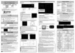
4.2. CPU_FAN1 (CPU FAN socket)
This receptacle can be used for connecting CPU/system fan. Its pins are
defined below. The user shall make sure the fan is conforming.
4.4. F_USB1/ F_USB2 (frond-end USB pin)
In case the USB ports on the rear panel of the machine case are not enough,
the user can use the two sets of extension USB pins provided by this
motherboard. These ports support USB 2.0 devices. The definitions of the
1
2
3
PIN
Definition
1
GND
2
12V
3
SIGNAL
ports are described below:
1
10
2
4.3. CLR_CMOS(CMOS pin)
The correct time, system hardware and other information are saved in the
CMOS memory of the motherboard. The interruption the computer's power
won't cause the loss of this information, for the CMOS is powered by the
battery on the motherboard. The port is defined as follows:
1
PIN
11
2
3
Definition
1-2#
Normal
2-3
CLR_CMOS
PIN
Definition
PIN
1
5V
2
5V
3
USB D0-
4
USB D1-
5
USB D0+
6
USB D1+
7
GND
8
GND
9
NULL
10
NULL
Definition
12