1
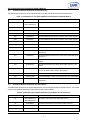
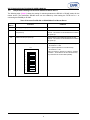
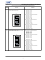
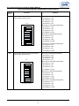
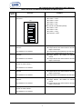
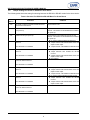
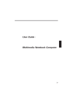
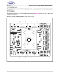
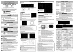
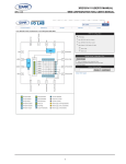
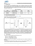
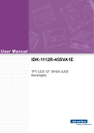
XR17V358/354 EVALUATION BOARD USER’S MANUAL
REV. 1.0.1
1.0 INTRODUCTION
This user’s manual is for the XR17V358/354 evaluation board revision 3.x. The XR17V358 and XR17V354 are
available in the same package and are pin compatible, therefore they share the same evaluation board. This
user’s manual gives an overview of the evaluation board and the jumper settings for testing various modes
using the evaluation board. The ordering information for the XR17V358/354 evaluation board is as following:
ORDERING INFORMATION
PART NUMBER
DESCRIPTION
XR17V354IB-0A-EVB
Single device XR17V354 is installed on the board.
XR17V354IB-E4-EVB
Two devices are installed on the board. The master device is XR17V354. The slave device
on expansion interface is a XR17V354.
XR17V354IB-E8-EVB
Two devices are installed on the board. The master device is XR17V354. The slave device
on expansion interface is a XR17V358.
XR17V358IB-0A-EVB
Single device XR17V358 is installed on the board.
XR17V358IB-E4-EVB
Two devices are installed on the board. The master device is XR17V358. The slave device
on expansion interface is a XR17V354.
XR17V358IB-E8-EVB
Two devices are installed on the board. The master device is XR17V358. The slave device
on expansion interface is a XR17V358.
2.0 OVERVIEW
This evaluation board has a x1 PCIe connector and will work in any x1, x4 or x16 PCIe slot. Up to 16 UART
ports can be tested on this evaluation board when 2 XR17V358 are installed. The PCIe interface of the master
device is connected directly to the PCIe connector. The master device communicates with the slave device via
Exar’s proprietary expansion interface. The PCIe interface on the slave device is not used.
FIGURE 1. PCIE AND EXPANSION INTERFACE
CLK+
CLK+
CLK-
CLK-
RX+
RX-
XR17V358/354
Master
Device
Expansion
Interface
XR17V358/354
Slave
Device
RX+
RX-
TX+
TX+
TX-
TX-
1
XR17V358/354 EVALUATION BOARD USER’S MANUAL
2.1
REV. 1.0.1
Evaluation Board Components for Master Device
The table below shows all of the components that are on the evaluation board for the master device.
TABLE 1: COMPONENTS OF THE XR17V358 EVALUATION BOARD FOR MASTER DEVICE
2.2
UNIT
PART
FUNCTION
U2
XR17V358IB176-F
XR17V354IB176-F
U16
SP336EEY-L
Exar RS-232/RS-485 Transceiver for master device UART channel 0.
U11
SP336EEY-L
Exar RS-232/RS-485 Transceiver for master device UART channel 1.
U25
SP336EEY-L
Exar RS-232/RS-485 Transceiver for master device UART channel 2.
U24
SP336EEY-L
Exar RS-232/RS-485 Transceiver for master device UART channel 3.
U28
SP336EEY-L
Exar RS-232/RS-485 Transceiver for master device UART channel 4.
U27
SP336EEY-L
Exar RS-232/RS-485 Transceiver for master device UART channel 5.
U17
SP336EEY-L
Exar RS-232/RS-485 Transceiver for master device UART channel 6.
U22
SP336EEY-L
Exar RS-232/RS-485 Transceiver for master device UART channel 7.
U6
SP336EEY-L
Exar RS-232/RS-485 Transceiver for master device UART RI# signals
channels 0-3.
U13
SP336EEY-L
Exar RS-232/RS-485 Transceiver for master device UART RI# signals
channels 4-7.
U9
SP3497EEN-L
Exar RS-485 Transceiver for master device UART channel 4. Not
installed.
U10
SP3497EEN-L
Exar RS-485 Transceiver for master device UART channel 5. Not
installed.
U21
SP336EEY-L
U3
HSDL2300
U26
93C46 (PDIP)
External EEPROM for storing Vendor ID and Device ID. Not installed.
U30
93C46 (TSSOP)
External EEPROM for storing Vendor ID and Device ID. Installed, not
programmed.
XR17V358 or XR17V354 PCIe UART master device.
Exar RS-232/RS-485 Transceiver for master device UART channel 3
and 4 for RS-485 full-duplex testing. Not installed.
IR Transceiver. Not installed.
Evaluation Board Components for Slave Device
The table below shows all of the components that are on the evaluation board for the slave device. If the slave
device is not installed, then these components will also not be installed.
TABLE 2: COMPONENTS OF THE XR17V358 EVALUATION BOARD FOR SLAVE DEVICE
UNIT
PART
FUNCTION
U1
XR17V358IB176-F
XR17V354IB176-F
U5
SP3245EEA-L
Exar RS-232 Transceiver for slave device UART channel 0.
U4
SP3245EEA-L
Exar RS-232 Transceiver for slave device UART channel 1.
U8
SP3245EEA-L
Exar RS-232 Transceiver for slave device UART channel 2.
XR17V358 or XR17V354 PCIe UART slave device.
2
XR17V358/354 EVALUATION BOARD USER’S MANUAL
REV. 1.0.1
TABLE 2: COMPONENTS OF THE XR17V358 EVALUATION BOARD FOR SLAVE DEVICE
2.3
UNIT
PART
FUNCTION
U7
SP3245EEA-L
Exar RS-232 Transceiver for slave device UART channel 3.
U15
SP3245EEA-L
Exar RS-232 Transceiver for slave device UART channel 4.
U14
SP3245EEA-L
Exar RS-232 Transceiver for slave device UART channel 5.
U19
SP3245EEA-L
Exar RS-232 Transceiver for slave device UART channel 6.
U20
SP3245EEA-L
Exar RS-232 Transceiver for slave device UART channel 7.
U12
SP3497EEN-L
Exar RS-485 Transceiver for slave device UART channel 4.
U18
SP3497EEN-L
Exar RS-485 Transceiver for slave device UART channel 5.
U23
SP336EEY-L
Exar RS-232/RS-485 Transceiver for slave device UART channel 3
and 4 for RS-485 full-duplex testing. Not installed.
Jumper Settings for Power Sources for Master Device
The following table shows the jumper settings for selecting/enabling the power source for the Master Device.
TABLE 3: JUMPER SETTINGS FOR POWER SOURCES FOR MASTER DEVICE
JUMPER
FUNCTIONS
COMMENTS
J45
3.3V supply voltage for the 3.3V Core
Not installed. Trace between 1&2.
J42
Enables/Disables Internal Buck Regulator
Jumper is not in - Internal buck regulator is enabled
(default).
J66
3.3V supply voltage for the output stage of buck regulator Not installed. Trace between 1&2.
J63
3.3V supply voltage for analog blocks of buck regulator
Not installed. Trace between 1&2.
J62
1.2V regulated voltage from internal buck
Not installed. Trace between 1&2.
J67
1.2V supply voltage for 1.2V PHY
Not installed. Trace between 1&2.
J56
1.2V supply voltage for 1.2V Core
Not installed. Trace between 1&2.
2.4
Jumper Settings for Power Sources for Slave Device
The following table shows the jumper settings for selecting/enabling the power source for the Slave Device.
TABLE 4: JUMPER SETTINGS FOR POWER SOURCES FOR SLAVE DEVICE
JUMPER
FUNCTIONS
COMMENTS
J32
3.3V supply voltage for the 3.3V Core
Not installed. Trace between 1&2.
J31
Enables/Disables Internal Buck Regulator
Jumper is not in - Internal buck regulator is enabled
(default).
J68
3.3V supply voltage for the output stage of buck regulator Not installed. Trace between 1&2.
J65
3.3V supply voltage for analog blocks of buck regulator
Not installed. Trace between 1&2.
J64
1.2V regulated voltage from internal buck
Not installed. Trace between 1&2.
J70
1.2V supply voltage for 1.2V PHY
Not installed. Trace between 1&2.
J34
1.2V supply voltage for 1.2V Core
Not installed. Trace between 1&2.
3
XR17V358/354 EVALUATION BOARD USER’S MANUAL
2.5
REV. 1.0.1
Jumper/Switch Settings for RS-232 or RS-485 for Master Device
The following table (Table 5) shows the setting for selecting between the RS-232 or RS-485 modes for the
master device. The Half-duplex RS-485 mode can be enabled by either setting the FCTR bit-5 to 1 or
connecting the EN485# pin to GND.
TABLE 5: SETTINGS FOR RS-232 OR RS-485 MODE FOR MASTER DEVICE
JUMPERS/
SWITCH
FUNCTIONS
COMMENTS
J13
3.3V Supply voltage pin for transceivers
Not installed. Trace between 1&2.
J41
Enable Auto RS-485 Half-Duplex Direction Control
upon power-up
Jumper between 1&2 enables this feature for all 8
channels. This feature can be disabled in the software
after power-up.
J54
Enable IR mode upon power-up
Jumper between 1&2 enables this feature for all 8
channels. This feature can be disabled in the software
after power-up.
SW5
Indicate whether slave device is presented or not.
Slave is not present (default for "0A-EVB" board).
■ Position 1 = OFF
Slave is present (default for "Ex-EVB" board).
■ Position 1 = ON
Position 2, Position 3, Position 4, Position 5, Position
6, Position 7, and Position 8 are for internal use only.
They should be set as OFF status (default).
SW5
OFF
ON
1
2
3
4
5
6
7
8
D efault for “0A -E VB”
4
XR17V358/354 EVALUATION BOARD USER’S MANUAL
REV. 1.0.1
TABLE 5: SETTINGS FOR RS-232 OR RS-485 MODE FOR MASTER DEVICE
JUMPERS/
SWITCH
SW1
FUNCTIONS
COMMENTS
Selects between RS-232 and half-duplex RS-485
mode for UART channels 0 and 1
SW1
OFF
ON
1
2
3
UART channel 0 RS-232 Mode (default)
■ Position 1 = OFF
■ Position 2 = OFF
■ Position 3 = ON
■ Position 4 = ON
UART channel 0 half-duplex RS-485 Mode
■ Position 1 = OFF
■ Position 2 = ON
■ Position 3 = OFF
■
UART channel 1 RS-232 Mode (default)
■ Position 5 = ON
■ Position 6 = ON
■ Position 7 = OFF
4
5
6
7
■
R S -2 3 2 M o d e (D e fa u lt)
■
Selects between RS-232 and half-duplex RS-485
mode for UART channels 2 and 3
SW4
OFF
Position 8 = OFF
UART channel 1 half-duplex RS-485 Mode
■ Position 5 = ON
■ Position 6 = OFF
■ Position 7 = ON
8
SW4
Position 4 = ON
ON
1
2
3
Position 8 = OFF
UART channel 2 RS-232 Mode (default)
■ Position 1 = OFF
■ Position 2 = OFF
■ Position 3 = ON
■ Position 4 = ON
UART channel 2 half-duplex RS-485 Mode
■ Position 1 = OFF
■ Position 2 = ON
■ Position 3 = OFF
■
Position 4 = ON
UART channel 3 RS-232 Mode (default)
■ Position 5 = ON
■ Position 6 = ON
■ Position 7 = OFF
4
5
6
7
■
Position 8 = OFF
UART channel 3 half-duplex RS-485 Mode
■ Position 5 = ON
■ Position 6 = OFF
■ Position 7 = ON
8
RS-232 Mode (Default)
■
5
Position 8 = OFF
XR17V358/354 EVALUATION BOARD USER’S MANUAL
REV. 1.0.1
TABLE 5: SETTINGS FOR RS-232 OR RS-485 MODE FOR MASTER DEVICE
JUMPERS/
SWITCH
SW6
FUNCTIONS
COMMENTS
Selects between RS-232 and half-duplex RS-485
mode for UART channels 4 and 5
SW6
OF F
ON
1
2
3
UART channel 4 RS-232 Mode (default)
■ Position 1 = OFF
■ Position 2 = OFF
■ Position 3 = ON
■ Position 4 = ON
UART channel 4 half-duplex RS-485 Mode
■ Position 1 = OFF
■ Position 2 = ON
■ Position 3 = OFF
■
4
UART channel 5 RS-232 Mode (default)
■ Position 5 = ON
■ Position 6 = ON
■ Position 7 = OFF
5
6
7
■
8
■
Selects between RS-232 and half-duplex RS-485
mode for UART channels 6 and 7
SW3
OFF
Position 8 = OFF
UART channel 5 half-duplex RS-485 Mode
■ Position 5 = ON
■ Position 6 = OFF
■ Position 7 = ON
R S-232 M ode (D efault)
SW3
Position 4 = ON
ON
1
2
3
Position 8 = OFF
UART channel 6 RS-232 Mode (default)
■ Position 1 = OFF
■ Position 2 = OFF
■ Position 3 = ON
■ Position 4 = ON
UART channel 6 half-duplex RS-485 Mode
■ Position 1 = OFF
■ Position 2 = ON
■ Position 3 = OFF
■
Position 4 = ON
UART channel 7 RS-232 Mode (default)
■ Position 5 = ON
■ Position 6 = ON
■ Position 7 = OFF
4
5
6
7
■
Position 8 = OFF
UART channel 7 half-duplex RS-485 Mode
■ Position 5 = ON
■ Position 6 = OFF
■ Position 7 = ON
8
RS-232 Mode (Default)
■
6
Position 8 = OFF
XR17V358/354 EVALUATION BOARD USER’S MANUAL
REV. 1.0.1
TABLE 5: SETTINGS FOR RS-232 OR RS-485 MODE FOR MASTER DEVICE
JUMPERS/
SWITCH
SW2
FUNCTIONS
COMMENTS
Enables the RI# signals in RS-232 mode for UART
channels 0-7
SW2
OF F
ON
1
2
3
4
UART channel 0 RS-232 Mode (default)
■ Position 1 = OFF
■ Position 2 = OFF
■ Position 3 = ON
■ Position 4 = ON
UART channel 1 RS-232 Mode (default)
■ Position 5 = ON
■ Position 6 = ON
■ Position 7 = OFF
■
Position 8 = OFF
Half-Duplex RS-485 control select for DE for UART
channel 3
■
Note: SP3497E is not installed.
■
No jumper installed enables RS-485 driver
Jumper between 2&3 selects RTS# as the halfduplex control output
Jumper between 1&2 disables the RS-485 driver
Half-Duplex RS-485 control select for RE# for UART
channel 3
■
Note: SP3497E is not installed.
■
Half-Duplex RS-485 control for transmitter and
receiver for UART channel 3
■
Not installed
Half-Duplex RS-485 control select for DE for UART
channel 4
■
Note: SP3497E is not installed.
■
No jumper installed enables RS-485 driver
Jumper between 2&3 selects RTS# as the halfduplex control output
Jumper between 1&2 disables the RS-485 driver
Half-Duplex RS-485 control select for RE# for UART
channel 4
■
Note: SP3497E is not installed.
■
Half-Duplex RS-485 control for transmitter and
receiver for UART channel 4
■
5
6
7
8
R S-232 M ode (D efault)
J14
J17
J10
■
■
No jumper installed disables RS-485 receiver
Jumper between 1&2 enables the RS-485
receiver
Jumper between 2&3 selects RTS# as the halfduplex control output
Note: SP3497E is not installed.
J16
J19
J8
Note: SP3497E is not installed.
7
■
■
No jumper installed disables RS-485 receiver
Jumper between 1&2 enables the RS-485
receiver
Jumper between 2&3 selects RTS# as the halfduplex control output
Not installed
XR17V358/354 EVALUATION BOARD USER’S MANUAL
2.6
REV. 1.0.1
Jumper Settings for RS-232 or RS-485 for Slave Device
The following table shows the setting for selecting between the RS-232 or RS-485 modes for the slave device:
TABLE 6: SETTINGS FOR RS-232 OR RS-485 MODE FOR SLAVE DEVICE
JUMPERS/
SWITCH
FUNCTIONS
COMMENTS
J23
3.3V supply voltage for RS-232 and RS-485 Transceivers for the slave device
Jumper between 1&2
J29
Enable Auto RS-485 Half-Duplex Direction Control
upon power-up
Jumper between 1&2 enables this feature for all 8
channels. This feature can be disabled in the software
after power-up.
J37
Enable IR mode upon power-up
Jumper between 1&2 enables this feature for all 8
channels. This feature can be disabled in the software
after power-up.
J15
Half-Duplex RS-485 control select for DE for UART
channel 3
■
Note: SP3497E is not installed.
■
Half-Duplex RS-485 control select for RE# for UART
channel 3
■
Note: SP3497E is not installed.
■
Half-Duplex RS-485 control for transmitter and
receiver for UART channel 3
■
Not installed
Half-Duplex RS-485 control select for DE for UART
channel 4
■
Note: SP3497E is not installed.
■
No jumper installed enables RS-485 driver
Jumper between 2&3 selects RTS# as the halfduplex control output
Jumper between 1&2 disables the RS-485 driver
Half-Duplex RS-485 control select for RE# for UART
channel 4
■
Note: SP3497E is not installed.
■
Half-Duplex RS-485 control for transmitter and
receiver for UART channel 4
■
J18
J12
■
■
No jumper installed enables RS-485 driver
Jumper between 2&3 selects RTS# as the halfduplex control output
Jumper between 1&2 disables the RS-485 driver
No jumper installed disables RS-485 receiver
Jumper between 1&2 enables the RS-485
receiver
Jumper between 2&3 selects RTS# as the halfduplex control output
Note: SP3497E is not installed.
J24
J28
J25
Note: SP3497E is not installed.
8
■
■
No jumper installed disables RS-485 receiver
Jumper between 1&2 enables the RS-485
receiver
Jumper between 2&3 selects RTS# as the halfduplex control output
Not installed
XR17V358/354 EVALUATION BOARD USER’S MANUAL
REV. 1.0.1
2.7
Pinout for connectors
The RS232 signals on the evaluation board goes to the SCSI type ultra micro DB68 connector. Figure 2 shows
the DB68 connector on the board. Table 7 shows the pinout.
FIGURE 2. DB68 CONNECTOR
TABLE 7: PINOUT FOR THE DB68
PIN NUMBER
SIGNAL
NAME
PIN NUMBER
SIGNAL
NAME
PIN NUMBER
SIGNAL
NAME
PIN NUMBER
SIGNAL
NAME
1
RXD7
18
RXD3
35
RXD8
52
RXD4
2
CT7
19
CT3
36
CT8
53
CT4
3
RIN7
20
RIN3
37
RIN8
54
RIN4
4
RT7
21
RT3
38
RT8
55
RT4
5
DCD7
22
DCD3
39
DCD8
56
DCD4
6
DT7
23
DT3
40
DT8
57
DT4
7
DS7
24
DS3
41
DS8
58
DS4
8
TXD7
25
TXD3
42
TXD8
59
TXD4
9
GND
26
GND
43
GND
60
GND
10
TXD5
27
TXD1
44
TXD6
61
TXD2
11
DS5
28
DS1
45
DS6
62
DS2
12
DT5
29
DT1
46
DT6
63
DT2
13
DCD5
30
DCD1
47
DCD6
64
DCD2
14
RT5
31
RT1
48
RT6
65
RT2
15
RIN5
32
RIN1
49
RIN6
66
RIN2
16
CT5
33
CT1
50
CT6
67
CT2
17
RXD5
34
RXD1
51
RXD6
68
RXD2
9
XR17V358/354 EVALUATION BOARD USER’S MANUAL
REV. 1.0.1
Figure 3 shows the DB9 cnnector. Table 8 shows the DB9 connector pinout.
FIGURE 3. DB9 CONNECTOR
TABLE 8: DB9 CONNECTOR PINOUT
PIN NUMBER
1
2
3
4
5
6
7
8
9
SIGNAL
DCDx
RXDx
TXDx
DTx
GND
DSx
RTx
CTx
RINx
2.8
MPIO pins
The MPIO pins of the both the master and slave devices are connected to LEDs or test points on the
evaluation board. Refer to page 6 of the evaluation board schematic for details.
3.0 DRIVERS
Software drivers for Windows and Linux are available from Exar. Send an e-mail with your driver request to
[email protected].
NOTICE
EXAR Corporation reserves the right to make changes to the products contained in this publication in order to
improve design, performance or reliability. EXAR Corporation assumes no responsibility for the use of any
circuits described herein, conveys no license under any patent or other right, and makes no representation that
the circuits are free of patent infringement. Charts and schedules contained here in are only for illustration
purposes and may vary depending upon a user’s specific application. While the information in this publication
has been carefully checked; no responsibility, however, is assumed for inaccuracies.
EXAR Corporation does not recommend the use of any of its products in life support applications where the
failure or malfunction of the product can reasonably be expected to cause failure of the life support system or
to significantly affect its safety or effectiveness. Products are not authorized for use in such applications unless
EXAR Corporation receives, in writing, assurances to its satisfaction that: (a) the risk of injury or damage has
been minimized; (b) the user assumes all such risks; (c) potential liability of EXAR Corporation is adequately
protected under the circumstances.
Copyright 2011 EXAR Corporation
Datasheet June 2011.
Send your UART technical inquiry with technical details to hotline: [email protected].
Reproduction, in part or whole, without the prior written consent of EXAR Corporation is prohibited.
10