1
AEMC® Instruments d.b.a. Chauvin Arnoux®, Inc.
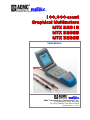
100,000-count
Graphical Multimeters
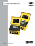
MTX 3281B
MTX 3282B
MTX 3283B
USER MANUAL
AEMC® Instruments d.b.a. Chauvin Arnoux®, Inc.
15 Faraday Drive • Dover, NH 03820
Tel. (603) 749-6434 • Fax: (603) 742-2346
99-MAN 100340 – v6 – 06/14
General instructions
Contents
General Instructions ..................................................................................................................................... 3
Introduction ......................................................................................................................................................................3
Symbols used on the instrument ...................................................................................................................................3
Precautions and safety measures .................................................................................................................................3
Safety features .................................................................................................................................................................4
Maintenance, metrological verification..........................................................................................................................4
Warranty ............................................................................................................................................................................4
Cleaning ............................................................................................................................................................................4
Measurement input protection systems ........................................................................................................................5
Special functions .............................................................................................................................................................5
Description of the instrument ...................................................................................................................... 6
Front, keyboards (illustration) ........................................................................................................................................6
Rear (illustration, markings) ...........................................................................................................................................6
Measurement terminal block (illustration, markings) ..................................................................................................6
Front (description) ...........................................................................................................................................................7
Inputs .................................................................................................................................................................................9
Display...............................................................................................................................................................................9
Functional description ................................................................................................................................ 10
Preparation for use ........................................................................................................................................................10
Initial settings .................................................................................................................................................................14
Specific configurations of the instrument ...................................................................................................................15
Initialisation of the values .............................................................................................................................................16
Access to main functions..............................................................................................................................................17
Range management .......................................................................................................................................................18
Display HOLD management HOLD, REL, SURV, SPEC, MEM...................................................................................18
Access to secondary functions ....................................................................................................................................25
MATH Function ...............................................................................................................................................................27
Favorite function ............................................................................................................................................................29
SX-DMM Software kit (option) ......................................................................................................................................31
Bluetooth (on –BT version) ...........................................................................................................................................31
Technical specifications ............................................................................................................................. 33
Voltage measurement ....................................................................................................................................................33
Current measurement ....................................................................................................................................................35
Frequency measurement ..............................................................................................................................................36
Resistance measurement ..............................................................................................................................................37
Continuity mode .............................................................................................................................................................37
Test diode .......................................................................................................................................................................37
Capacitance measurement ...........................................................................................................................................38
Temperature measurement with Pt100 or Pt1000 sensor (MTX 3282B, MTX 3283B) .............................................38
Temperature measurement with J or K thermocouple ..............................................................................................38
dBm measurement .........................................................................................................................................................38
Positive or negative peak measurement .....................................................................................................................39
Resistive power ..............................................................................................................................................................39
Duty ratio DC+, DC- ........................................................................................................................................................39
Pulse counting CNT+, CNT- ..........................................................................................................................................39
Clock ................................................................................................................................................................................40
Influences........................................................................................................................................................................40
Multimeter traceability, calibration...............................................................................................................................40
General specifications ................................................................................................................................ 41
Environmental conditions .............................................................................................................................................41
Power ..............................................................................................................................................................................41
Display.............................................................................................................................................................................41
Safety...............................................................................................................................................................................42
CEM .................................................................................................................................................................................42
RS232 DB9F and USB optical cables (options) ..........................................................................................................42
Mechanical characteristics ......................................................................................................................... 42
Box ...................................................................................................................................................................................42
Packaging .......................................................................................................................................................................42
Supply, accessories .................................................................................................................................... 43
Index ............................................................................................................................................................. 44
2
100,000-count Graphical Multimeters
General instructions
General instructions
Introduction
You have just acquired a 100,000-count graphical multimeter.
Thank you for your trust in our products.
It complies with safety standard EN 61010-1 (2001), double insulation, relative
to electronic measuring instruments.
For optimum service, read this MANUAL carefully and comply with the
operating precautions.
Warning: Risk of danger.
Refer to the operating MANUAL to find out the nature of the potential hazards and
the action necessary to avoid such hazards.
Symbols used on
the instrument
Earth terminal
Equipment protected throughout by double insulation.
The rubbish bin with a line through it means that in the European Union, the product
must undergo selective disposal for the recycling of electric and electronic material,
in compliance with Directive WEEE 2002/96/EC.
Attention : Risk of electrical shock
Read carefully all the notes preceded by the symbol
.
If you use this instrument in a way which is not specified, the protection
which it provides may be compromised, putting you in danger.
The safety of any system incorporating this instrument is the responsibility of
the system assembler.
This instrument has been designed for use indoors:
- in an environment with pollution level 2,
- at an altitude of less than 2000 m,
- at a temperature between 0° C and 55° C
- with relative humidity of less than 80% up to 31° C.
Precautions and
safety measures
Measurement category III for voltages no higher than 1000 V (AC or DC) in
relation to the earth.
Measurement category IV for voltages no higher than 600 V (AC or DC) in
relation to the earth.
Definition of
measurement
categories
CAT III: Measurement category III corresponds to measurements on building installations.
Example: measurements on distribution panels, cabling, etc.
CAT IV : Measurement category IV corresponds to measurements taken at the source of lowvoltage installations
Example: metering and measurements on overvoltage protection devices...
Comply with environmental and storage conditions.
For your safety, only use the leads delivered with the instrument:
they comply with the norm EN 61010-1 (2001).
Before using it, systematically check that it is in perfect condition.
before use
during use
As a safety measure, use only suitable leads and accessories supplied
with the instrument or approved by the manufacturer.
If the measurement category of the accessory is different from that of the
apparatus, the lowest category applies to the unit.
Never exceed the protection limit values indicated in the specifications for
each type of measurement.
Before changing the function, disconnect the measurement leads from the
circuit measured.
Never measure resistances on a live circuit.
When the instrument is connected to the measurement circuits, never touch
an unused terminal.
100,000-count Graphical Multimeters
3
General instructions
General instructions (cont’d)
Safety features
Maintenance and
metrological
verification
It is impossible to access the battery or fuse compartment without first
disconnecting the measurement leads.
When measuring voltages greater than 60 VDC or 30 VAC, the
flashes on the display.
Automatic detection of a connection on the "Ampere" terminal.
symbol
When there is a persistent range overrun, an intermittent buzzer indicates the
risk of electric shock.
Any access to the internal circuits for adjustment, servicing or repair of the unit
under power must be undertaken only by qualified personnel, after reading the
instructions in this MANUAL.
A qualified person is a person who is familiar with the installation, its
construction, its use and the hazards that exist. They are authorized to activate
and deactivate the installation and equipment, in compliance with the safety
instructions.
For all repairs under or outside of the warranty, return the device to your retailer.
Warranty
This equipment is guaranteed for 3 years against any defect in materials or
workmanship, in accordance with the general terms and conditions of sale.
During this period, the equipment can only be repaired by the manufacturer. The
manufacturer reserves the right to carry out repair or replacement of all or part of
the equipment.
If the equipment is returned to the manufacturer, initial transport costs shall be
borne by the customer.
The warranty does not apply in the event of:
unsuitable use of the equipment or use with other incompatible equipment
modification of the equipment without explicit authorization from the
manufacturer’s technical services
repair carried out by a person not certified by the manufacturer
adaptation to a specific application, not provided for in the definition of the
equipment or by the operating MANUAL
an impact, a fall or flooding.
Unpacking repacking
All the equipment was verified mechanically and electrically before shipping.
When you receive it, carry out a quick check to detect any damage that may
have occurred during transport. If necessary, contact our sales department
immediately and register any legal reservations with the carrier.
In the event of reshipping, it is preferable to use the original package. Indicate
the reasons for the return as clearly as possible in a note attached to the
equipment.
Cleaning
4
Turn the instrument off.
Clean it with a damp cloth and soap.
Never use abrasive products or solvents.
Allow to dry before any further use.
100,000-count Graphical Multimeters
General instructions
General instructions (cont’d)
Measurement input
protection systems
These multimeters are equipped with several protection systems:
Varistor protection clips any transient overvoltages on the measurement
terminals.
PTC (positive temperature coefficient) protection protects against permanent
overvoltages less than or equal to 1000 V during capacitance or resistance
measurements and diode tests.
This protection is reset automatically after the overload.
A fuse (11 A) provides protection during intensity measurements.
Special functions
Automatic current
measurement
detection
The number of input terminals is limited to 3: V, COM, A. Connection of the lead
to the "Ampere" terminal automatically selects the corresponding function.
When a function modification by the control keyboard is incompatible
with the lead connection, it triggers a buzzer and a visual alarm (LEADS).
The current measurement is performed using autorange over the whole range.
Auto power-off
If the function is validated in the Sleep menu: the instrument shuts down
automatically after 30 minutes if no action has occurred on the front panel during
that time.
The instrument can be powered up again by pressing the
Alert signal
key.
Automatic power-off is inhibited in:
Surveillance mode (SURV)
Memorize mode (MEM)
Communication mode
(optical link - RS232C, USB, Bluetooth)
when the value measured (Voltage or Current) on the multimeter's
inputs exceeds the danger level.
An intermittent buzzer sounds:
on the "Voltage" position, when the range is exceeded (MANUAL and
AUTO mode - last range)
on the "Current" position, when the range is exceeded (MANUAL) mode,
when 10 Amperes or more is measured
if the position of the leads and the function selected are incompatible
when the danger thresholds are exceeded (function activated)
When the range is exceeded, the buzzer is accompanied by display of "O. L".
Danger threshold
When this symbol is activated:
the voltage on the "Volt" input exceeds 60 VDC or 30 VAC
the current injected between the "Ampere" and COM exceeds 10 A
the range is exceeded (voltage or current) in MANUAL mode
100,000-count Graphical Multimeters
5
Description of the instrument
Description of the instrument
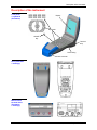
Front panel
+ keyboards
(illustration)
Display
Keyboards
ON/OFF
Key
Terminal
strip
Lower casing
Jack connector
Rear (illustration
+ markings)
Measurement
terminal block
(illustration
+ markings)
6
100,000-count Graphical Multimeters
Description of the instrument
Description of the instrument (cont'd)
Front (description)
1 power on/off key
Starting the multimeter.
Stopping the multimeter.
If there is a multimeter malfunction, a long press (> 1 s) on this key can be
used to return to normal operation.
8 keys for selecting the main functions
Voltage measurement or access to the measurement type: AC, DC or AC+DC
Selection using this key or the
Validation using the
keys.
key or after 2 s.
Current measurement or access to the measurement type: AC, DC or AC+DC
Selection using this key or the
Validation using the
keys.
key or after 2 s.
Measurement of Frequency (Hz) on a VAC voltage or access to the MANUAL
frequency range < 900 kHz (default) or > 900 kHz.
A long press opens the menu for changing the voltage range.
Selection using the
keys.
Validation using the
or
keys.
Voltage range quick change using the
keys.
The selected range is recalled in the help line (i), see page 9.
Measurement of Resistance (Ohm)
By pressing again:
Access to the Continuity test (
Access to Diode test (
)
)
Measurement of Temperature or access to the types of temperature
measurements: ° C, ° F or K.
Selection using the
keys.
Validation using the
key or after 2 s.
By pressing this key during measurement type selection, you can access
the sensor type:
- platinum probes: Pt 100, Pt 1000 only on MTX 3282B and MTX 3283B
- thermocouples: J (TC J), K (TC K)
Selection using the
keys.
Validation using the
key or after 2 s.
The selected scale is recalled in the help line (i), see page 9.
Measurement of Capacitance
"Favorite" measurement configurable by the user.
A long press opens the "favorite" function configuration menu.
For the menu's configuration, see §. Function.
100,000-count Graphical Multimeters
7
Description of the instrument
Description of the instrument (cont'd)
Instrument Configuration menu.
This key can also be used to exit from a menu or submenu after validating it.
3 keys for navigation and
modification of the menus
Selection of a menu or function (up/down navigation).
Increase or decrease of the variable selected.
Selection of a function (left/right navigation).
Modification of a function.
Movement within sub-menus.
6 keys for activating the
instrument's various modes
Selection of the operating mode:
AUTO, AUTO PEAK ( MTX 3282B, MTX 3283B ), MANUAL.
Selection using this key or the
keys.
Validation using the
key or after 2 s.
If the measurement is single range, the range defined is forced and there is no
effect if this key is pressed.
Example: Diode test, continuity test and temperature measurement.
By pressing one of the
keys, you can switch directly to MANUAL mode
and then modify the range.
Activation, deactivation of the REL (relative) mode.
When it is active, a long press opens a window for setting the reference.
Activation, deactivation of the display of the specifications for the function and
range selected.
Activation of HOLD or AUTO HOLD mode, deactivation NO HOLD.
Selection using this key or the
Validation using the
keys.
key or after 2 s.
Activation, deactivation of the SURV (surveillance) mode.
A long press opens a window for viewing the most recent records.
Closed by a short press.
Activation, deactivation of the MEM (automatic recording) mode.
A long press opens the MEM Function menu.
2 utility keys
Back-lighting of the display in dark environments.
A long press opens the menu for adjusting the contrast on the LCD.
Selection of the functions for the 3 secondary displays.
Selection by successive presses on this key.
A long press can be used to exit from this mode.
8
100,000-count Graphical Multimeters
Description of the instrument
Description of the instrument (cont'd)
Inputs
Input for voltage and frequency measurements, diode tests, resistance
measurements, continuity tests, and capacitance or temperature
measurements.
Input for current measurements.
Reference input.
Display
The multimeters in this range are equipped with a graphical LCD screen
(58 mm x 58 mm) with 160 x 160 resolution for comfortable reading.
Reading of the LCD can be optimized by varying the orientation of the
display, the adjustment of contrast and, if necessary, using the backlighting.
(foot of the screen) i
The modes, the functions selected, the electrical or physical values
measured and the alert symbols are clearly shown on the display.
The user can call up help (i) regarding the function selected.
The main display is accompanied by its sign and the unit.
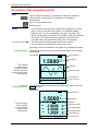
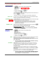
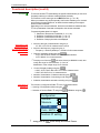
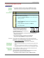
Depending on the current selections, the display may be graphical or digital:
Graphical display
The graphical window can be used to monitor the evolution of the principal
measurement.
Example
Upper status line
AUTO
1.5000
The graphical
DC
1
0
window and the
bargraph constantly
track the evolution of
the measurement in the
range selected.
Bargraph
Graphical window
-
1
0
> 60s
HOLD
i
Display of
secondary functions
Main display
V
Lower status line
Help on function
Press the main function key …
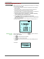
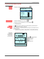
The secondary displays are intended for the SPEC, REL, MEM, SURV and
888888 functions:
Example
AUTO
Upper status line
1.5000 V
DC
The main display
-10
and the bargraph
constantly track the
evolution of the
measurement.
0
MIN
MAX
AVG
-1.0000 V
2.5000 VV
2.5000
1.3000 V
SURV MEM 2
i
100,000-count Graphical Multimeters
Recording started
Main display
Bargraph
10
Secondary display 1
Secondary display 2
Secondary display 3
Lower status line
Help on function
9
Functional description
Functional description
Preparation for use
Instructions before
activation
Instrument
power supply
To use this instrument, you must comply with the usual safety rules in order:
- to protect you against the dangers of the electric current,
- to protect the multimeter against incorrect operations.
For your safety, only use the leads delivered with the instrument. Before
using it, systematically check that it is in perfect condition.
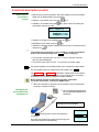
The 3 multimeters in this range operate with three 1.5 V alkaline batteries
(LR6-AM3 AA) or three 1.2 V Ni-MH rechargeable batteries (accumulators)
of the same type:
The MTX 3281B is delivered with three 1.5 V alkaline batteries
(LR6-AM3 AA). It can operate with accumulators, but does not allow in
situ recharging (see §. Accessories delivered as options).
The MTX 3282B and MTX 3283B multimeters are delivered with three 1.2
V
Ni-MH accumulators and charger (12 VDC 7.2 VA) for AC power operation
while simultaneously charging the batteries.
When the charger is connected directly to the instrument, the
accumulators can be recharged without removing them from the
multimeter.
The multimeter can only operate if the accu./batteries are in place.
Power on
Charge indicator
Using the key opposite.
A charge status indicator for the batteries or accumulators is constantly
shown on the display:
: Batteries or accumulators > 75 % charged
: Batteries or accumulators > 25 % charged
: minimum charge level < 25 %
The
symbol flashes on the display and a buzzer sounds if the power
voltage is insufficient (only 30 min charge life).
As the specifications will no longer be guaranteed, you must then replace
the batteries or recharge the accumulators (see next page).
There can be differences between the display of the charge level (symbol)
and the real charge level of the accumulators, according to the quality and
the performances of those.
To avoid this risk, we recommend to use the same accumulators (HX0051)
as those delivered by the manufacturer (see p. 43).
When getting started, the apparatus needs a few seconds to display a
correct level of charge (symbol).
10
100,000-count Graphical Multimeters
Functional description
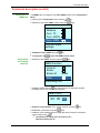
Functional description (cont'd)
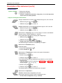
Selection of
energy type
For correct management of the battery or accumulator charge status indicator,
the type of power must be selected:
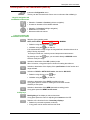
Opening of the Configuration menu with the
key.
Selection of the "General" function using the
keys.
Validation of General settings using the
key.
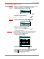
Configuration
General
Measure
Func.
Func. MATH
General settings
Selection of Energy Type menu using the
keys.
General
IR baud
9600
Config
user
Energy
bat.
Accumulator
Energy type
Modification of the Energy Type (battery or acc.) using the
Validation and exit from the successive menus using the
Recharging the
accumulators
key.
key.
Before carrying out this operation, check that the accumulators are fitted in the
instrument ; they do not need to be removed from the multimeter to be
recharged.
Recharging is only possible if "Accumulator" has been selected in the Energy
Type menu (see above).
If you try to recharge the accumulators when the batteries are fitted in the
multimeter, it could damage it.
For safety reasons, the accumulators should only be loaded at between 0 and
40°C.
Caution
100,000-count Graphical Multimeters
High internal temperature due to a current measurement may
trigger the thermal security mechanism.
11
Functional description
Functional description (cont'd)
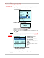
Recharging the
accumulators
(cont’d)
Before carrying out this operation, select the capacity of the accumulators
(2600 mAh by default) fitted in the instrument:
Selection: Accumulator in the using the
Validation: Accumulator using the
accumulator capacity (in mAh):
keys.
key, opens a menu for setting the
Acc. capacity
02600
mAh
Selection of the digit to be modified using the
Modification of the value using the
key.
key.
Validation of the accumulator capacity and exit from the successive menus
.
using the key
To maintain the accumulators in good condition, run the accumulators
down to the minimum charge level
before recharging.
Then connect the power pack (12 VDC, 7.2 VAC) to the jack connector
(see front panel illustration).
Connect the power pack (12 VDC, 7.2 VAC) to the AC Power supply.
The symbol opposite on the display allows you to monitor the charge status.
The accumulators are fully charged when the symbol is full
.
The MTX 3282B and MTX 3283B multimeters contain Ni-MH accumulators.
These accumulators must be disposed of by a recycling firm or a company
specialized in the treatment of dangerous waste materials.
Never dispose of these accumulators with other solid waste.
For further information, contact your AEMC dealer.
Recharging the
accumulators with
multimeter off
When the multimeter is delivered, the accumulators may be discharged,
requiring a complete recharge.
Do not connect the wall plug when
there are disposible batteries in the
instrument.
Connection of the wall plug starts
recharging the accumulators.
Battery charging
The
scrolling symbol shows the progress of
recharging.
Once the accumulators have been fully recharged, the
instrument shuts down automatically.
12
Charge level:
75%……..100%
100,000-count Graphical Multimeters
Functional description
Functional description (cont'd)
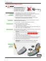
Wall plug Use only the charger that is
power unit delivered with this device, which
is a 2nd generation multimeter.
The charger from the previous
generation is not compatible.
Recharging totally
discharged
accumulators
or new batteries
1. Fit the batteries into the multimeter, then connect the charger.
2. Wait approximately 30 minutes, then press the ON button to switch on the
multimeter and follow the progress of the charge.
Average charging period : 7h30 (with 2600 mAh accumulators)
"A measurement”
protection fuse
After one effective hour of recharging, the multimeter can be used for
measurements, by pressing again on the ON button.
A fuse provides protection up to 11 A for current measurements. It must be
replaced only with an identical fuse:
11 A, 20 kA, 1000 V, 10 x 38 mm (High Interrupting Capacity).
Checking of current
measurement fuse
Test the current measurement as follows:
1. Select the Ampere function using the A key.
2. Connect a lead to the A terminal.
3. Check that the LEADS indication disappears from the display (presence of
lead). If this is not the case, replace the fuse.
Replacement of the
fuse or the batteries
Before replacing the fuse or batteries, comply with the safety instructions given
at the beginning of this MANUAL. Then:
1. Disconnect the test leads from the measurement circuits and the
instrument.
2. Disconnect the power lead from the MTX 3282B or MTX 3283B 12 VDC
power pack.
3. Switch off the power to the instrument.
4. Undo the screw on the back of the instrument.
5. Pivot the rear cover of the casing to access the battery/fuse compartment.
6. Remove the fuse or batteries and replace them with identical models.
7. Replace the cover and retighten the screw.
Without batteries, the date and time are kept for ca. 1 min in the
instrument.
The measurements recorded are kept for an unlimited time.
Dismantling of
multimeter and
access to
battery/fuse
compartment
fuse
batteries
slit for
screwdriver
100,000-count Graphical Multimeters
13
Functional description
Functional description (cont'd)
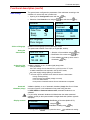
Initial settings
The general menu configures the parameters of the multimeter according to the
conditions of use and the user’s preferences.
Opening of the Configuration menu with the
key.
Selection of the General menu using the
General
Language
Date/Time
Beep
Sleep
En
Contrast
Back-light
Comm.
IR baud
on
off
10 s
IR
9600
Back-light auto-off
delay
Selection of the language for the multimeter's menus.
Two options are available: French (Fr) or English (En, default).
Setting the
date and time
Date and time
Selection of the variables using the
08 : 03 : 2005
10 : 03 : 45
Activation of the
buzzer (Beep)
key.
General
Set language
Choix langue
Choice of language
keys and then the
Modification of the value using
key.
keys.
Clock validation and start-up when menu is
key.
closed using
Validation (default), or not , of audio signal (beep) when:
- a key is pressed,
- there is a voltage of more than 60 VDC or 30 VAC on the "V" input,
- a stable measurement is acquired in AUTO HOLD mode,
- the power supply voltage (battery) is insufficient.
The audio signal is maintained even when the buzzer is deactivated :
Automatic
shutdown (sleep)
Display contrast
during continuity testing,
when the range is exceeded (voltage or current),
on a 10 A measurement,
if the position of the leads and the function selected are incompatible.
Validation (default), or not, of automatic shutdown (sleep) after 30 min if there
has been no action on the multimeter's front panel during that time.
In SURV, MEM and Communication modes, automatic shutdown is not
validated.
For your safety, automatic shutdown is inhibited when the values measured
(voltage, current) on the inputs exceed the danger thresholds (indicator opposite
displayed).
Modification of the value (default: 50 %)
Contrast
14
using the
key.
Validation of setting using
key.
A long press on
directly opens the menu,
validates the setting.
100,000-count Graphical Multimeters
Functional description
Functional description (cont'd)
Adjustment of
back-lighting
Start-up
configuration
(Config)
Selection of the back-lighting deactivation time to limit the multimeter's energy
consumption.
6 times are possible: 10 s, 30 s, 1 min, 2 min, 10 min or infinite (no
deactivation).
By default, the back-lighting deactivation time is 2 min.
In user mode, the instrument restarts with the user's personal configuration
and the main function selected when it was switched off.
In basic mode, by default, the multimeter restarts with its elementary
configuration and the Volt (AC+DC) function.
Specific
configurations
of the instrument
Restart configuration indicated without leads connected. If the leads
are connected, they will be taken into account for function selection.
Using the Measure menu, you can adapt the instrument's configuration to the
measurement environment:
Measure
Filter
yes
Impedance 1G
dBm REF
W REF
Filter activation
Filter
the
keys and then the
key.
By default, filter active.
Choice of the required input impedance on the 100 and 1000 mV (1 V) ranges.
- 100 mVDC and AC+DC range: 2 possible impedances: 1 G or 10 M
- 1000 mV mVDC range:
2 possible impedances: 1 G or 20 M
dBm REF
MTX 3283B
Selection of the Measure menu using
Activation of a filter to improve frequency rejection for measurements in low VDC
mode.
Impedance
Opening of the Configuration menu
key.
with the
By default, 100 mV range = 10 M, 1000 mV range = 20 M
Adjustment of the reference resistance value (dBm REF) between 1 and
10,000 , for measurements in dBm on VAC or VAC+VDC voltages:
Set dBm ref
00600
ohm
Selection of the digit to be modified using the
key.
Modification of the value using the
keys.
Validation of the reference resistance in dBm and exit from the menu using the
key.
Default value 600 .
Reminder A 0 dBm measurement with a 600 reference resistance is given on a voltage
of 0.7746 VAC.
100,000-count Graphical Multimeters
15
Functional description
Functional description (cont'd)
W REF
MTX 3283B
Adjustment of the reference resistance value (W REF) between 1 and
10,000 for resistive power measurements:
(voltage measured)2 / W REF (unit W)
(current measured)2 W REF (unit W)
The adjustment procedure is the same as for the dBm reference resistance.
The calculation performed is:
Initialization of the
values
Default value 50 .
W REF is used to calculate the resistive power (W) with
REF = W REF and to calculate the power (V A) when V (Ref) = W REF
The parameters of the configuration can be reinitialized to the default settings
in a single operation:
Opening of the Configuration menu with the
key.
Configuration
Func.
Func. MATH
Func. MEM
Default
init
Set default values
Selection of the "Default init"
keys.
function using the
Validation of initialization using the
key.
Loading of the default values is confirmed by the following message:
Message
Default values
loaded
Default values
The language and the active main
function are not modified.
Language :
Sleep :
Lighting :
IR baud :
Energy 3281B :
accu.
Accu. capacity :
Filter :
dBm REF :
Fr
on
2 min
9600
battery
Beep :
on
Contrast :
50 %
Communication : IR
Configuration :
basic
Energy 3282B, 3283B :
2600 mAh
active
600
Impedance :
W REF :
10 / 20 M
50
Favorite func.
MATH func.
Function :
Coef. A :
V
1
Unit :
Coef. B :
none
0
MEM func.
Recording freq. : 1 s
No. of rec. 3281B :
rec. 3282B, 3283B : 1000
158
No. of
Main func.
V, A :
AUTO, AC+DC
, Capacity :
AUTO
Hz :
°C:
10 V range
° C, Pt 100
General
Measure
16
Exit from the successive menus using
key.
the
100,000-count Graphical Multimeters
Functional description
Functional description (cont'd)
Access to main functions
Connection of leads
The input terminals are limited to 3 : COM, V, ,
and A.
Connect the black lead to the COM socket (for all measurements).
Functions authorized
when connected on
the V
terminal
Voltage measurement (Volt).
PEAK is displayed when a peak (Pk+ Pk-measurement) of voltage is detected
and when it is higher than the range of active voltage.
Measurement of Frequency (Hz) on a VAC voltage.
A 1st press gives access to Resistance measurements (Ohm).
A 2nd press gives access to Continuity measurements (
A 3rd press gives access to Diode measurements (
).
).
A 1st press gives access to Temperature measurements (according to the last
configuration of the function).
A 2nd press gives access to the type of temperature measurement: ° C, ° F, K.
Selection using the
keys, validation using the
key or after 2 s.
Another press on this key while selecting the measurement type gives access
to the type of sensors:
- platinum probes: Pt100 or Pt1000 only on MTX 3282B, MTX 3283B
- thermocouples: J or K (TC J, TC K)
Selection using the
keys, validation using the
key or after 2 s.
Measurement of Capacitance.
"Favorite" measurement configurable by the user.
For the menu's configuration, see §. Function.
Instrument Configuration menu.
Functions
authorized when
connected to the
A terminal
When the red lead is connected to the A terminal, it automatically selects
Current (AC + DC) measurement.
If current measurement is selected without connection of a lead to terminal A
or without a protection fuse, the LEADS symbol flashes on the display.
Current measurement (Ampere)
The current measurement may be performed using autorange
(AUTO PEAK) over the whole scope of the ranges (µA, mA, A).
PEAK is displayed when a peak (Pk+ Pk- measurement) of current is detected
and when it is higher than the range of active current.
"Favorite" measurement configurable by the user.
For the menu's configuration, see §. Function.
Instrument Configuration menu.
100,000-count Graphical Multimeters
17
Functional description
Functional description (cont'd)
Range management
key gives access to three operating modes:
The
- AUTO mode
- AUTO PEAK mode MTX 3282B, MTX 3283B
- MANU mode
Selection using this key or the
keys.
Validation using the
key or after 2 s.
If the measurement is single range, the range defined is forced and there is no
effect if the
key is pressed.
Example: Diode test, continuity test and temperature measurement.
“AUTO” mode
“AUTO PEAK” mode
MTX 3282B
MTX 3283B
“MANUAL” mode
On the input for a measurement, AUTO mode is active by default and range
selection is managed automatically by the multimeter.
In AUTO PEAK mode, the range changes are performed on the basis of rapid
acquisition of peaks, either upward or downward.
When this mode is selected and is valid for the function concerned, the
keys can be used to modify the measurement range.
Measurements concerned: voltage, current, resistance, capacitance.
Display hold
management
AUTO PEAK mode is only accessible for AC, AC+DC in V and A
measurements. It prevents untimely overruns of the peak factor
specified for the instrument.
By pressing one of the
keys, you can switch directly to MANUAL
mode and then modify the range.
key gives access to two operating modes:
The
- HOLD mode
- AUTO HOLD mode
- NO HOLD deactivates the mode.
Selection using this key or the
Validation using the
HOLD
The range selection remains unchanged: AUTO or MANUAL depending
on the configuration when you enter this mode.
AUTO HOLD mode automatically freezes on the screen the current main
measurement whenever a stable measurement is detected. It is confirmed
by a beep (unless the configuration "Beep no" has been selected in the
Configuration menu).
The values memorized remain displayed until the next stable measurement
taken (measurement different from ± 100 digits) or until deactivation of AUTO
HOLD mode.
The instrument continues to manage the measurements and display them in
the graphical window or on the secondary display (REL mode).
18
key or after 2 s.
HOLD mode freezes on the screen the current main measurement at the time
when the key is pressed. The instrument continues to manage the
measurements and display them in the graphical window or on the secondary
display (REL mode).
AUTO HOLD
keys.
The range selection remains unchanged (AUTO or MANUAL) depending
on the configuration when you enter this mode. AUTO HOLD mode is
only accessible for V and A measurements.
100,000-count Graphical Multimeters
Functional description
Functional description (cont'd)
REL
REL mode takes the current main measurement as its reference. It is indicated
on the secondary display: REF.
The main display continues to indicate the instantaneous value measured
and the bargraph.
The secondary display indicates the absolute deviation between the
instantaneous value measured and the reference recorded.
The secondary display % indicates the relative deviation in % between the
instantaneous value measured and the reference recorded.
Range management may be "AUTOmatic" or "MANUAL, depending
on the configuration when entering this mode.
The and % displays are managed in the same range.
In "AUTO" mode, they cannot fall below the reference range when the
REL mode was activated.
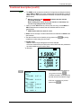
Example: Measurement of a 1.5 VDC voltage with a reference set to 1 V:
AUTO
REL
1.5000 V
DC
IIIIIII
-10
REF
%
Adjustment of the
reference
1.0000 V
0.5000 V
050.00 %
When the mode is active, a long press on the
setting the REF reference.
The
The
10
key opens a window for
key selects the digit to be modified.
keys modify the digit selected.
The
key can be used to exit from the menu after validating the new
reference.
Example:
Reference Rel
+1.0000
100,000-count Graphical Multimeters
19
Functional description
Functional description (cont'd)
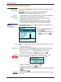
SURV
The SURV mode monitors the variations of a signal by recording the extreme
values (MIN and MAX) of the main measurement and calculating the average
(AVG). For each value memorized the multimeter records the corresponding
date and time.
When it is started up, the MTX 3281B reinitializes the date and time
(01:01:2000, 00:00:00).
Before starting work, set the correct date and time to "date-stamp" the
records see §. Setting the date and time).
When you enter SURV mode by a short press on the key, the last MIN and
MAX measurements are erased and then initialized with the current
measurement.
SURV flashes when the mode is active.
AVG shows the average of all the measurements recorded since SURV mode
was activated.
The data recorded can be viewed by a long press on the
surveillance or after exiting from the mode.
key during
In SURV mode:
- MANU or AUTO range management cannot be selected.
- the current measurement, the MIN value and the MAX value are presented in
the most suitable range for each of them.
Example:
AUTO
1.5000 V
DC
-10
MIN
MAX
AVG
0
-1.0000 V
2.5000 V
1.3000 V
10
SURV
Consultation of recorded data by a
SURV
long press on the key
Start :
27/03/2005
10 :07 :11
Stop :
27/03/2005
10 :10 :30
Mini : -1.0000 V
27/03/2005 10 :08 :25
The data recorded is accompanied by
the date, time and surveillance range.
Exit from consultation by a short
press on the
.
Max : 2.5000 V
27/03/2005 10 :09 :25
Avg : 1.3000
20
V
100,000-count Graphical Multimeters
Functional description
Functional description (cont'd)
SPEC
On the basis of the technical specifications, the SPEC mode directly displays
the tolerance of the measurement in progress, so that there is no need to
search for it and calculate it.
On the basis of the main measurement, the display:
indicates the specifications (x % of reading ± n digit) according to the type of
measurement, the range selected and the frequency (in AC and AC+DC)
calculates the interval containing the true value, if the instrument is within its
tolerance:
SMIN value minimum specification
SMAX value maximum specification
Example:
SPEC
1.0000 V
AC+DC
0
5
SMIN
SMAX
0.9930 V
1.0070 V
10
In AC+DC, the
specifications are
calculated only if the
frequency can be
measured (see §.
Secondary Functions)
and is > 45 Hz.
0.3%, 40 digits
MEM
MEM mode records the contents of the digital display(s) in the memory of the
instrument at a pre-programmed rate.
A short press on
starts a series of recordings.
The MEM symbol flashes throughout the recording period; it is accompanied
by the number of recordings made.
Memorization of the measurements can be stopped by another short press.
The number of values to be memorized for a measurement run is
programmable: it therefore stops recording automatically.
Another press on
MTX 3281B
Recording
MTX 3282B, MTX 3283B capacity
Example: activation
starts a new series of recordings.
158 measurements per sequence
1 to 10 sequences
6500 measurements maximum
1 to 10 sequences
(depending on available memory)
AUTO
of MEM mode during
surveillance mode
1.5000 V
DC
-10
MIN
MAX
AVG
0
-1.0000 V
2.5000 V
1.3000 V
10
Furthermore, the MEM
mode may be activated
during the SURV mode or
during display of the
secondary functions.
The parameters set
are saved.
It will then be possible to
select them and display
them as the main function.
SURV MEM 2
(When it is started up, the MTX 3281B reinitializes the date and time
(01:01:2000, 00:00:00).
Before starting work, set the correct date and time to "date-stamp" the
records. See §. Setting the date and time).
100,000-count Graphical Multimeters
21
Functional description
Functional description (cont'd)
Configuration of
MEM mode
The MEM mode is configured in the Func. MEM function of the Configuration
Menu.
Opening of the Configuration menu with the
key.
Selection of the "Func. MEM" function using the
Configuration
Measure
Func.
J
Func. MATH
Func. MEM
Function MEM
settings
Validation of Func. MEM using the
Programming
the recording
frequency
A long press on
keys.
key.
opens the MEM Function menu.
Selection of the "RATE" function using the
keys.
MEM Function
Consult
Erase
Erase all
erase
Rate
Recording rate
Validation of Rate with the
key opens a menu for setting the required
recording rate in hours, minutes and seconds:
Rate h:mn:s
00 : 00 : 02
Selection of the variables, hour, minute, second, using the
Modification of the value using the
key.
keys.
Validation of the measurement recording rate and exit from the successive
.
menus using the key
22
The minimum recording rate is 23 h, 59 min, 59 s.
Default recording rate 1s.
100,000-count Graphical Multimeters
Functional description
Functional description (cont'd)
Programming of the
number of records
By defining a number of records for a measurement campaign, it is possible to
stop recording automatically.
Selection of the number of records (No. rec.) in the MEM Function menu
.
using the keys
MEM Function
Erase
Erase all
Rate
No. rec.
Number of
recordings
Validation of No. rec. using the
erase
key.
Number of rec.
0100
Selection of the digit to be modified using the
key.
Modification of the value using the
keys.
Validation of the number of records and exit from the successive menus using
key.
the
Reminder
The recording capacity is limited to 6,500 measurements (158 for MTX 3281B)
Number of records by default : 1,000.
Reading the
recorded data
28/03/05 10:40:40
28/03/05 10:41:08
29/03/05 11:05:20
30/03/05 15:30:42
5 val. (2 s), V
Reminder
Select the Consult menu in the
Function to view the list or
successive records.
Recordings
Each recording is identified by its
start date and time.
Selection of a recording using the
keys.
Validation the selection using the
key.
When selected, a recording is accompanied by :
- the number of values recorded,
- the recording rate,
- the function in which they were recorded,
- the secondary functions present during recording, if relevant.
The number of recording sequences is limited to 10.
100,000-count Graphical Multimeters
23
Functional description
Functional description (cont'd)
Viewing the data
in a recording
The curve displayed is adapted to the graphical window according to its min.
and max. values and the number of recordings.
Cursor value
Max. value of the
selected function
↕ 6.5832
DC
9.9275
9.9275 V
V
MIN
MAX
AVG
V
-8.2194
9.9275
2.3271
V
V
V
Secondary
functions
Cursor
Display of zoomed
part
Zoomed part of
recording
Min. value of the
selected function
Function of graph
displayed
Overall display of
whole recording
-8.2194
-8.2194 V
V
100/450
100/450
V
28
28 :: 03
03 :: 05
05
10
10 :: 40
40 :: 40
40
Cursor position / Total no. of records
Selection
icons
Cursor date and time
Selection of the function (principal or secondary) to be displayed or of the
selection icon using the
keys, modification using the
V Selection of the function to be displayed
key.
Example: Main function: V
MTX 3281B
MTX 3282B
MTX 3283B
secondary function: MIN, MAX, AVG for SURV mode
moves the cursor
moves the zoomed part (icon present, if a zoom is active)
activates/deactivates a zoom (icon present, if a zoom is possible)
Exit from viewing a recording by using the
Complete erasure of
memory
All recordings in the memory of the device may be erased in a single operation.
Selection of Erase all menu in the MEM Function.
Validation of erasure using the
key.
Complete erasure of the memory is
confirmed by the following message
24
key.
Message
erased
100,000-count Graphical Multimeters
Functional description
Functional description (cont’d)
Access to secondary
functions
Choice of secondary functions on the two displays 2, 3 and 4 by pressing
successively on the key opposite according to main measurement.
A long pressing deletes the display of secondary measurements.
Table of secondary
functions
Refer to page 9.
For the main authorized measurements, the last combination selected for
displays 2, 3 and 4 is memorized and will be directly reactivated.
Display 2
Display 3
Function Unit
Function
Display 4
Display 1: Main measurement
VAC
Unit
VAC+DC
MTX 3281B / 2 / 3
FREQ
Hz
PER
S
Func. MATH
x
MTX 3283B
FREQ
Hz
dB
dB
Func. MATH
x
MTX 3283B
dBm
dBm
REF (dBm)
Func. MATH
x
MTX 3281B / 2 / 3
V or A Pk-
Pk+
V or A
-
CF
VDC
AAC
AAC+DC
ADC
Hz
x
x
x
w
W
REF ()
Func. MATH
MTX 3281B / 2 / 3
PER
S
DC+
%
Func. MATH
x
MTX 3281B / 2 / 3
PER
S
DC-
%
Func. MATH
x
MTX 3282B / 3
PW+
S
CNT+
-
Func. MATH
x
MTX 3282B / 3
PW-
S
CNT-
-
Func. MATH
x
MTX 3282B / 3
Func. MATH
-
-
-
MTX 3282B / 3
VxA
A
Func. MATH
MTX 3283B
VA
A
x
x
x
x
x
x ()
x
Function MATH = y = Ax + B ( MTX 3282B, MTX 3283B)
FREQ = Frequency measurement
PER
= Period measurement
dB
= Measurement of voltage decibels in dB
dBm = Measurement of power decibels in dBm with REF = dBm REF
Pk+
= Measurement of positive peaks ( )
Pk= Measurement of negative peaks ( )
CF
= Measurement of peak factor
w
= Calculation of resistive power with REF = W REF
V x A = Calculation of power ( ) limited to 400 Hz
DC+
= Measurement of positive duty ratio
DC= Measurement of negative duty ratio
PW+ = Measurement of pulse-width or of positive durations
PW= Measurement of pulse-width or of negative durations
CNT+ = Counting of positive pulses
( )
CNT- = Counting of negative pulses
( )
(
)
Measurement reset to zero: by pressing on
key.
For optimal use, refer to §. Technical Specifications.
100,000-count Graphical Multimeters
25
Functional description
Functional description (cont’d)
Access to secondary
functions (cont’d)
MTX 3283B
Upon activation of dB measurements, the value measured is taken as voltage
reference (V ref).
The calculation is as follows:
20 log10 (V measured / V ref).
The voltage reference (V ref) cannot be modified.
The MATH function is displayed when its parameters allow it (see MATH Func.).
For the dBm and resistive power measurements, see Measurement menu for
the adjustment of related reference resistances (dBm REF, W REF) and to
know the calculation formulas.
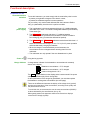
MTX 3282B MTX
3283B
The calculation of power V x A (VA) requests a 3rd connection to the A input
(connected to the same circuit) in order to measure simultaneously: DC voltage
(main display), DC power (display 3, measurement always in AC+DC).
The link on the COM input must be short and have a large diameter in
order to limit the voltage drop which influences the Volt measurement.
LOAD
V COM A
26
100,000-count Graphical Multimeters
Functional description
Functional description (cont’d)
MATH function
MTX 3282B
MTX 3283B
The MATH function (y = Ax + B) enables measuring any physical quantity in:
- Volts
(0 - 10 V process or high-voltage probe, for example)
- Amperes
(current loop 4 - 20 mA or current clamp, for example)
- Frequency (output measurement, rotation speeds, for example)
- Ohms
(resistive position, for example)
and converting it and to assign the adequate unit, to obtain the direct reading of
the original parameter on the instrument. Depending on the parameter measured,
the device calculates the related MATH function.
The programming takes place in 4 phases:
Selection of parameter X measured (V, A, , Hz)
Definition of coefficient A of function y = Ax + B
Definition of coefficient B of function y = Ax + B
Definition of physical unit to be displayed
Adjustment of
MATH function
Coefficients A, B and the unit are programmable for each amount
measured (V, A, , Hz).
The MATH mode is configured in the MATH function in the Configuration Menu.
Opening of Configuration Menu using key
.
Selection of function MATH Func. using keys
.
Configuration
General
Measure
Func.
Func. MATH
MATH function
settings
Validation of MATH Func. using key
Selection of
function to be
adjusted
.
Selection of Function menu using keys
.
MATH function
Function
Coef A
Coef B
Unit
V
Function to be set
Selection of measurement (V, A, , Hz) using key
.
Default function V.
100,000-count Graphical Multimeters
27
Functional description
Functional description (cont’d)
Definition of
coefficient A
The MATH function applied to the physical quantity (x) measured is y = Ax + B.
Selection of the coefficient A menu (Coef A) in MATH function.
Validation of Coef A (coefficient A) using key
.
Coef.
Coef. A
A
+2.0000
E+01
+2.0000
E+01
Selection of digit to be modified or of exponent using key
Modification of value using keys
.
.
Validation of coefficient A and menu exit using key
.
Coefficient A by default is 1.
Definition of
coefficient B
Selection of coefficient B menu (Coef B) in MATH function.
Validation of Coef B (coefficient B) using key
.
Coef. B
-1.0000
E+00
Selection of digit to be modified using key
Modification of value using keys
.
.
Validation of coefficient B and menu exit using key
.
Coefficient B by default is 0.
Definition of unit
The unit of the MATH function may be defined so as to obtain the direct
reading of the original physical quantity measured by the instrument.
Selection of Unit menu in MATH function.
Validation of Unit using key
.
Unit
Abc_
A B C
H I J
OPQ
VWX
D
K
R
Y
E
L
S
Z
F G
MN
T U
Selection of letter or character to display using key
Validation of letter or character using keys
.
.
Validation of the unit (3 characters max.) and menu exit using key
.
The symbol is used to switch from uppercase letters to lowercase.
The symbol is used to erase the last character.
MATH unit by default (without).
28
100,000-count Graphical Multimeters
Functional description
Functional description (cont’d)
Function The favorite function recalls directly the specific measurement you use most
frequently and that you will have carefully defined previously.
This function is of the same type as the MATH function (y = Ax + B).
When you measure any physical quantity, this function enables you to convert it
and to assign the appropriate unit, to obtain the direct reading of the original
amount on the instrument.
Depending on the amount measured, the device calculates the related function
, if the parameters of the latter correspond to the amount measured.
Programming takes place in 4 stages:
1. Selection of the amount X measured (V, A, , Hz)
2. Definition of coefficient A of function y = Ax + B
3. Definition of coefficient B of function y = Ax + B
4. Definition of the physical unit to be displayed
Access to the type of measurement using key
- AC, DC or AC+DC for measurements V and A
Application of the
favorite function
acc. to its programmed
measurements
(V, A, , Hz)
Access to the frequency range using key
- Frequency < 900 kHz (default) or > 900 kHz for Hz measurements
Control of operating modes using key
:
- AUTO, AUTO PEAK, MANU for V and A measurements
- AUTO, MANU for measurements
Pressing one of the keys
will switch directly to MANUAL mode, then
modify the range for measurements V, A and .
Modification of the voltage range for Hz function.
Control of display holding using key
:
- HOLD, AUTO HOLD, NO HOLD for V and A measurements
- HOLD, NO HOLD for , Hz measurements
Activation, deactivation of relative mode using key
Activation, deactivation of monitoring mode using key
Activation, deactivation automatic recording using key
Adjustment of
function
The function is configured in Func. in the Configuration Menu.
Opening of Configuration Menu using key
Selection of function Func.
using keys
.
. Validation using key
.
Configuration
General
Measure
Func.
Func. MATH
Function setting
A long press on
100,000-count Graphical Multimeters
opens directly the Function menu.
29
Functional description
Functional description (cont’d)
Selection of
adjustment
parameters
Selection of adjustment parameters using keys
.
Function
Function
Coef A
Coef B
Unit
V
Function selection
Selection of amount
measured (function)
Selection of Function menu using keys
.
Selection of amount measured (V, A, , Hz) using key
Definition of
coefficients A, B
and unit
.
Default function V.
The favorite function applied to the physical quantity (x) measured is the
same as the MATH function (y = Ax + B).
For the definition of coefficients A, B and the unit, see the related menus of
the MATH function.
Coefficient A is by default 1, B by default 0, unit by default (without).
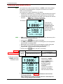
Example:
activation of
favorite function
and automatic
recording mode
AUTO
1.5000
DC
W
1
0
MEM 2
i
30
> 60s
- Symbol of favorite function
- AUTO Mode active
- DC Measurement
- W Unit
- MEM Mode active
1
0
Recording started
100,000-count Graphical Multimeters
Functional description
Functional description (cont’d)
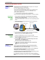
SX-DMM
Software kit
(option)
These multimeters can interface directly with a computer or a PC using the
SX-DMM software kit (Cat. # 2125.80 option):
In the menu General settings of the multimeter:
- Select infra-red communication (IR by default) using the Comm function.
- Select the infra-red transmission speed using the IR baud function:
9600 / 19,200 / 38,400 Bauds/s.
The transmission speed by default is 9600 Bauds/s.
The other transmission parameters are set (8 data bits, 1 stop bit, no parity).
Connection of
optical cables
RS232-DB9F
or USB
(option)
1. Then connect the optical cable to the optical input of the multimeter
(located next to the multimeter inputs). A mechanical failsafe prevents
reversing of the connection direction.
Connect cable RS232-DB9F or USB to one of the corresponding inputs of
the PC.
2. Verify that the RS232 interface parameters of the PC are identical to
those of the multimeter.
Connector DB9F or USB
Interface cable
Optical connector
Installation of
SX-DMM
software
For the USB optical cable (option), install, if necessary, the recognition
software on your PC (see CD-Rom MANUAL provided).
1. Install the SX-DMM software on the PC using the CD ROM.
2. Launch the software to perform data acquisition and study the different
display possibilities (curves, tables…).
The symbol
(RS232) flashes on the display during control of the
instrument from the PC (REMOTE mode).
For more information, refer to software help menu.
In this mode, the multimeter keyboard is locked, except for key
which is used to exit this mode.
Bluetooth
(on -BT version)
The -BT versions of the multimeters are fitted with a Bluetooth module.
They integrate the Serial Port Profile service used to communicate with a
computer fitted with any type of Bluetooth adapter.
If your computer does not have a Bluetooth module, the PC USB/Bluetooth
adapter (Cat. # 2125.84) is required.
To install these pilots, refer to the accompanying instructions.
Virtual RS232 serial communication between the multimeter (Server) and the
PC (Customer) requires a connection on the PC side.
No configuration is required on the multimeter side, except for activation of
Bluetooth (BT) communication via the Comm. function in the General Settings
menu.
100,000-count Graphical Multimeters
31
Functional description
Functional description (cont’d)
Bluetooth (cont’d)
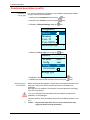
Creating a
Bluetooth
connection
(for first
connection only)
The controls cited below are those of the PC USB/Bluetooth adapter
(P01637301). They may be designated differently on another adapter.
Steps
Actions
1
Power up the multimeter.
2
Configure it for Bluetooth (BT) via the configuration menu.
3
Create a new connection using the software controlling your
Bluetooth dongle on the PC side by:
clicking on the Bluetooth Manager icon on the menu bar at the
bottom of the screen
selecting the New connection function
selecting Express Mode (recommended), then clicking on Next
selecting the Bluetooth peripheral of the multimeter then by
clicking on Next
clicking on Next after configuration of a COM port
redefining the name of the connection and its icon (if required)
then clicking on Next
clicking on Finish to save the connection information
You can verify that the connection has been
created by viewing it, using the software
controlling your PC USB/Bluetooth adapter.
For additional information, refer to the Help menu
linked to the Bluetooth utility.
Connect
Disconnect
With some Bluetooth adapters, rebooting of the PC is recommended to
validate the connection.
Example
Reactivation of
the connection
after shutdown
Communication
with several
multimeters
Communication with SX-DMM software can begin without other Bluetooth
configurations. You must simply establish communication between the PC and
the multimeter using the COM port configured previously.
Command SX-DMM software: Communication Parameters
Click on the Bluetooth Manager icon on the menu bar at the bottom of the
screen
Click on the icon related to the multimeter in the window of the Bluetooth
Parameters Software: the icon of the menu bar must be displayed in green.
The PC USB/Bluetooth adapter is used to communicate simultaneously with
several multimeters in the MTX Mobile family.
For each multimeter, you must repeat the previous configuration procedure,
while making sure to assign them a different COM port.
32
The connection parameters are specific to each multimeter.
They must be assigned MANUALY, but only the first time.
Depending on the type of adapter, first make a COM port available.
100,000-count Graphical Multimeters
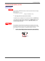
Technical specifications
Technical specifications
Accuracy:
"n% +nD" means
"n% of reading + n Digit"
(as per IEC 485)
Only the values assigned a tolerance or a limit constitute guaranteed values.
Values without tolerance are given for information (standard NFC 42670).
The technical specifications are guaranteed only after 30 min warm-up period.
Except special indication, they are valid from 5 to 100% of the range of measurement.
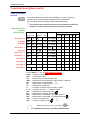
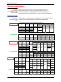
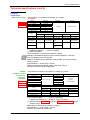
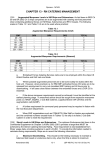
Voltage measurement
AC voltage
VAC and VAC+DC
TRMS
MTX 3281B
On this position, you measure the true RMS value of an AC voltage with its DC
component (no capacitive coupling): so-called TRMS measurement.
The 100 mV range is present in MANUAL mode only.
Input
impedance
100 mV ()
1G - 10M
1 µV
1000 mV
10.5 M
10 µV
10 V
10.5 M
0,1 mV
1 mV
Range
Input
impedance
Resolution
100 mV
10 M
1 µV
1 µV
1000 mV
10.5 M
10 µV
10 V
10.5 M
0,1 mV
100 V
10 M
1 mV
1000 V ()
10 M
10 mV
Input
Resolution
impedance
10 M
1 µV
Input
Resolution Protection
impedance
1 µV
(1 mn max)
100 mV () 1G - 10M
1000 mV
10.5 M
10 µV
10 V
10.5 M
0.1 mV
100 V ()
10 M
1 mV
10 M
10 mV
Range
100 mV
Input
Resolution
impedance
10 M
100,000-count graphical multimeters
5 µV
1450 Vpk
1 kHz to
4 kHz
4 kHz to
20 kHz
20 kHz to
50 kHz
3% of R ±
40cts
4% of R ±
40cts
6% of R ±
40cts
1% of R ± 40cts
Accuracy
Input
Resolution Protection
impedance
100 mV
( ) In VAC mode
1450 Vpk
10 mV
Range
1000 V ()
0.7% of R ±
40cts
10 M
100 mV () 1G - 10M
45 Hz to
1 kHz
(1 mn max) 1% of R ± 40cts
10 M
Range
Range
Protection
100 V
( ) In VAC mode
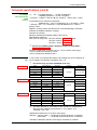
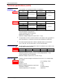
MTX 3283B
Resolution
1000 V ()
( ) In VAC mode
MTX 3282B
Accuracy
Range
Protection
1450 Vpk
(1mn max)
45 Hz to
400 Hz
400 Hz to
4 kHz
4 kHz to
20 kHz
20 kHz to
50 kHz
1.5% of R ±
40cts
3% of R ±
40cts
4% of R ±
40cts
6% of R ±
40cts
Accuracy
(1 mn
max)
45 Hz to
1 kHz
1% of R ±
40cts
0.5% of R ±
40cts
1450 Vpk
0.3% of R ±
40cts
1 kHz to
4 kHz
4 kHz to
20 kHz
20 kHz to
50 kHz
2.5% of R 3.5% of R ± 5% of R ±
± 40cts
40cts
40cts
50 kHz to 75 kHz to
75 kHz
100 kHz
7% of R ± 10% typ of
40cts
R ± 40cts
10% of R ±
40cts
7% of R ±
40cts
0.5% of R ±
40cts
15% of R ±
40cts
(1mn max)
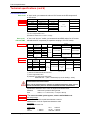
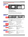
Accuracy
45 Hz to 400 Hz to 1 kHz to 20 kHz to 50 kHz to 75 kHz to
400 Hz
14 kHz
20 kHz
50 kHz
75 kHz
100 kHz
1.5% of R 2.5% of R ± 3.5% of R ± 5% of R ± 7% of R ± 15% typ of
± 40cts
40cts
40cts
40cts
40cts
R ± 40cts
45 Hz to
1 kHz
1 kHz to
4 kHz
Protection
1450 Vpk
Accuracy
4 kHz to
20 kHz
20 kHz to
50 kHz
0.5%of R ± 2.5%of R ± 3% of R ±
40ct
40cts
40cts
4% of R±
40cts
0.3%of R ±
40cts
0.4%of R ±
40cts
50 kHz to
75 kHz
7% typ of
10% typ. of
R
R ± 40cts
± 40cts
1.5%of R ± 2.5% of R 3.5% of R
40cts
± 40cts
± 40cts 5% of R±
40cts
1%of R ±
40cts
75 kHz to 100 kHz to
100 kHz
200 kHz
2% of R ± 3% of R ±
40cts
40cts
8% typ.of 20% typ.of
R ± 40cts R ± 40cts
10% of R ±
30cts
7% of R ±
40cts 15% of R ±
40cts
Accuracy
Protection
45 Hz to
400 Hz
400 Hz to
4 kHz
4 kHz to
20 kHz
20 kHz to
50 kHz
50 kHz to
75 kHz
75 kHz to 100 kHz to
100 kHz
200 kHz
1450 Vpk 1.5% of R
(1mn max)
± 40cts
3% of R ±
40cts
3.5% of R
±40cts
4% of R ± 5% of R ±
40cts
40cts
7% typ.of 10% typ.of
R ± 40cts R ± 40cts
33
Technical specifications
Technical specifications (cont’d)
AC voltage () BP : Freq [kHz] limited to : 15,000 / U applied [V]
U applied [V] limited to : 15,000 / Freq [kHz]
VAC and VAC+DC
Example
:
U applied = 1000 VAC max. frequency : 15,000 / 1000 = 15 kHz
TRMS
(cont’d) In the presence of a continuous component :
Additional error : (UDC / U measured) x (0,7% of reading + 70cts)
Example : UDC = 2 V, U measured = 5 Vrms additional error : 0.28% of
reading + 28cts
Rejection: common mode > 80 dB at 50 Hz or 60 Hz depending on selection
Automatic or MANUAL selection of ranges.
Protection by varistors.
Maximum permanent acceptable voltage: 1000 VACrms.
Specifications valid from:
20 to 100% of range in the 20 kHz to 200 kHz MTX 3283B band,
20 kHz to 100 kHz MTX 3282B
20 kHz to 50 kHz MTX 3281B.
As soon as the PEAK symbol is displayed, connect to AUTO PEAK :
MTX 3282B MTX 3283B
Influence of peak factor on accuracy in VAC, VAC+DC at 50% of the range:
1% for a peak factor between 4,5 and 6
5% for a peak factor between 6 and 9
DC voltage
VDC
In "DC" mode, you measure the value of a DC voltage or the DC component of
an AC voltage, once the filter is activated, see p. 15.
MTX 3281B
MTX 3282B
MTX 3283B
The 100 mV range is present in MANUAL mode only.
Range
Input impedance
20 M / 1 G
10 µV
10.5 M
0.1 mV
100 V
10 M
1.0 mV
1000 V
10 M
10 mV
Input impedance
Resolution
1 µV
100 mV ()
10 M / 1 G
1000 mV
20 M / 1 G
10 µV
10 V
10.5 M
0.1 mV
100 V
10 M
1.0 mV
1000 V
10 M
10 mV
Range
Input impedance
Protection
1 µV
10 V
Range
10 M / 1 G
Resolution
100 mV ()
1000 mV
Resolution
1 µV
100 mV ()
10 M / 1 G
1000 mV
20 M / 1 G
10 µV
10 V
10.5 M
0.1 mV
Accuracy
0.1% of R + 30cts
1450 Vpk
0.1% of R + 8cts
0.2% of R + 8cts
Protection
Accuracy
0.1% od R + 30cts
0.05% of R + 8cts
1450 Vpk
0.03% of R + 8cts
0.035% of R + 8cts
Protection
Accuracy
0.1% of R + 30cts
0.05% of R + 8cts
1450 Vpk
() - Recovery
after triggering
of protection
100 V
1.0 mV(> 10 V) app. 10 s.
10 M
- Protection
1 minute
max.
1000 V
10 mV
10 M
0.02% of R + 8cts
0.03% of R + 8cts
() - Accuracy with filter (p. 15) and REL mode activated ( measurement).
- Recovery after release of the protection (> 10 V) approx. 10 s.
- Protection 1 min. max.
Specifications valid from 0 % to 100 % of the range
Rejection: common mode: > 120 dB with 50 Hz and 60 Hz acc. to selection
serial mode:
> 60 dB with 50 Hz and 60 Hz acc. to selection
Automatic or MANUAL selection of the ranges. Protection by varistors.
34
100,000-count graphical multimeters
Technical specifications
Technical specifications (cont’d)
Current measurement
ADC current In "ADC" mode, you measure the value of a DC current or the DC component of
an AC current.
MTX 3281B
MTX 3282B
MTX 3283B
Range
Input impedance
Resolution
1000 µA
approx. 170
10 nA
10 mA
approx. 17
0.1 µA
100 mA
approx. 1.7
1 µA
1000 mA
approx. 0.17
10 A
Accuracy
0.1% of R + 15cts
0.08% of R + 8cts
11 A
20 A < 30 s
10 µA
0.15% of R + 8cts
100 µA
approx. 0.03 ()
100 A ()
Protection
0.5% of R + 15cts
1000 µA
() with the fuse delivered with the instrument
() 100 A range limited to 20 A
Specifications valid from 0 % to 100 % of range
AAC current,
AAC+DC TRMS
MTX 3281B
In "AAC" and "AAC+DC" modes, you measure the true RMS value of an AC current
with/without its DC component (no capacitive coupling in "AC+DC" mode).
Range
Input
impedance
1000 µA
approx. 170
10 nA
Protect.
Accuracy
45 Hz to 1 kHz
10 mA
approx. 17
0.1 µA
approx. 1.7
1 µA
1000 mA
approx. 0.17
10 µA
10 A
approx. 0.03
()
100 µA
1.5% of R ± 30cts
1000 µA
2.5% of R ± 30cts
Range
Input
impedance
Resolution
1000 µA
approx. 170
10 nA
10 mA
approx. 17
0.1 µA
100 mA
approx. 1.7
1 µA
1000 mA
approx.
0.17
10 A
approx.
10 µA
100 µA
1 kHz to 4 kHz
11 A
20A<30s
Protection
11 A
20A < 30s
1% of R ± 30cts
4 kHz to 20 kHz
5% of R ± 30cts
1% of R ± 40cts
100 mA
100 A ()
MTX 3282B
MTX 3283B
Resol.
1.5% of R ± 30cts
3% of R ± 30cts
3% of R ± 30cts
5% of R ± 30cts
Accuracy
45 Hz to 1 kHz
1 kHz to 4 kHz
4 kHz to 20 kHz
20 to 50 kHz
0.5% of R ± 40cts
1% of R± 30ctcs
5% ± 30D
-
0.3% of R ± 30cts
1.5% of R ±
30cts
5% of R ± 30cts
3% of R ± 30cts
1.5%of R± 30cts
2% f R
30 t
() with the fuse delivered with the instrument
() 100 A range limited to 20 A
In presence of a continuous component :
additional error : (I DC / I measured) x (0.7% of reading + 70cts)
A max. overload of 20 A is acceptable for 30 s max. with a pause of 5 min at
least between each measurement.
From 7 A, the measurement is limited to an ambient temperature of 40° C and a
period of 1h30 with a pause of 15 min at least between each measurement.
Specifications valid from 10% to 100% of range for sinusoidal current.
Protection
1000 Vrms by ceramic HRC type fuse
Fuse
1000 V, 11 A > 20 kA Cos > 0.9 (10 x 38 mm)
MTX 3282B
As soon as the PEAK symbol appears, switch to AUTO PEAK mode :
MTX 3283B mA and µA range:
Additional error of 2% for a peak factor between 4.5 and 6
Additional error of 15% for a peak factor between 6 and 9
10 A range:
Zero up to peak factor of 6.
Voltage drop:
1 mA
100 mA
100,000-count graphical multimeters
160 mV
180 mV
10 A
< 400 mV
10 mA 180 mV
1000 mA 300 mV
35
Technical specifications
Technical specifications (cont’d)
Frequency
measurement
Main frequency (Hz)
MTX 3281B
MTX 3282B
MTX 3283B
In this position, you measure the frequency of a voltage.
AC Signals
Range
0.8 to 10 Hz
10 to 100 Hz
100 to 1000 Hz
1000 Hz to 10 kHz
10 to 100 kHz
100 to 1000 kHz
1 MHz to 2 MHz
Resolution
0.0001 Hz
0.001 Hz
0.01 Hz
0.1 Hz
1 Hz
10 Hz
100 Hz
Protection
Accuracy
1450 Vpk
0.02% of R± 8cts
Sensitivity (applicable on rectangular signals only)
Range
100 mV
1V
10 V
100 V
1000 V
0.8 Hz to 10 Hz
15 % of range
25 % of range
15 % of range
15 % of range
15 % of range
10 Hz to 100 kHz
10 % of range
20 % of range
10 % of range
10 % of range
10 % of range ()
100 to 500 kHz
()
20 % of range
20 % of range
()
20 % of range ()
-
-
-
-
500 to 1000 kHz
1 MHz to 2 MHz
typ. 20 % of
range
typ. 30 % of
range
typ. 50 % of
range
() Freq [kHz] limited to:
15,000 / U applied [V]
U applied [V] limited to:
15,000 / Freq [kHz]
() limited to 200 kHz
The measurement is performed by capacitive coupling.
Selection of the MANUAL frequency range < 900 kHz (default) or > 900 kHz,
via a short pressing of the key opposite.
Selection of voltage range in MANUAL mode possible, via a long pressing of
the key opposite.
Input resistance: 10 M (Freq < 100 Hz)
Maximum permanent acceptable voltage: 1000 Vrms. See ().
Protection by varistors at the voltage input
Parallel
voltage or current
or frequency
(secondary
function)
MTX 3281B
MTX 3282B
MTX 3283B
You measure the frequency and value of a voltage or a current.
Range
Accuracy
Resolution
Admissible overload
0.8 to 10 Hz
0.0001 Hz
10 to 100 Hz
0.001 Hz
100 to 1000 Hz
1000 to 10 kHz
0.1 Hz
10 to 100 kHz
1 Hz
100 to 200 kHz
10 Hz
Range
1450 Vdc
(1 min max.)
on 500 mV range
0.01 Hz
0.02 % or R + 8cts
Sensitivity (applicable on rectangular signals only) Vrms
100 mV
1V
10 V to 1000 V ()
0.8 Hz to 5 kHz
15 % of range
20 % of range
15 % of range
20 % of range
5 kHz to 50 kHz
10 % of range
20 % of range
10 % of range
20 % of range
50 kHz to 100 kHz
15 % of range
25 % of range
15 % of range
100 kHz to 200 kHz
-
30 % of range
30 % of range
1000 µA to 20 A ()
-
() Freq limited to [kHz]:
15,000 / U applied [V]
U applied [V] limited to [V]: 15,000 [V kHz] / Freq [kHz]
() limited to 20 kHz MTX 3281B ; at 50 kHz MTX 3282B, MTX 3283B for the
"Ampere" range
Measurement is performed by capacitive coupling
Input resistance: 10 M (Freq < 100 Hz)
Protection by varistors at voltage input
36
100,000-count graphical multimeters
Technical specifications
Technical specifications (cont’d)
In this position, you measure the value of a resistance.
Resistance
measurement ()
MTX 3281B
Range
Accuracy
Resolution
1000
10 m
10 k
100 m
100 k
0.1 % of R + 8cts
1
MTX 3282B
MTX 3283B
1000 Vrms
10
1000 k
10 M
0.5 % of R+ 8cts
100
50 M
2 % of R+ 8cts
1 k
Range
Accuracy
Resolution
1 000
0.1 % of R + 8cts
10 k
100 k
Protection
Protection
10 m
100 m
0.07% of R + 8cts
1
1000 Vrms
10
1000 k
10 M
0.5% of R + 8cts
100
50 M
2 % of R + 8cts
1 k
Automatic/MANUAL range selection
"Active" protection via CTP thermistor
Measurement voltage: ca. 1.2 V
Maximum voltage developed on open circuit: 4 V typ
In range 50 M, in order to avoid the influence of the network and to guarantee the
given specifications, it is advised to disconnect the multimeter from Wall Plug.
For measurements higher than 10 M, a shielded cable is recommended.
For a 2 wire-link, use very short wires (< 25 cm) and twist them.
Continuity Mode ( )
MTX 3281B
MTX 3282B
MTX 3283B
On this position, you can measure the value of a resistance up to 1000 , with
steady audio indication at 2 kHz.
Range
Accuracy
Measuring current
Resolution
Protection
Beeper
0.1% of R + 8cts
approx. 0.4 mA
100 m
1000 Vrms
Detection threshold in continuity mode 120 (response time 5 ms).
"Active" protection via CTP thermistor.
Maximum voltage on open circuit: 4 V max, 2 V typ.
Diode Test (
)
MTX 3281B
MTX 3282B
MTX 3283B
Indication of junction voltage in the direction from 0 to 2.6 V in a single range
(10 V range)
Accuracy
2 % of reading ± 30cts
Resolution
0.1 mV
Measuring current
< 1 mA
Maximum voltage developed on open circuit
4 V max.
"Exceeded" indication
in reverse direction
"Active" protection by CTP thermistor
1000 Vrms
100,000-count graphical multimeters
37
Technical specifications
Technical specifications (cont’d)
In this position, you can measure the value of a capacitor.
Capacitance
measurement
(
)
MTX 3281B
MTX 3282B
MTX 3283B
Range
Accuracy
Resolution
10 nF ()
100 nF
1 % of r + 10cts
10 pF
0,2 s
100 pF
0,5 s
1000 nF
10 µF
100 µF
1000 µF
10 mF
1 % of reading +
5cts
1 % of r+ 15cts
1.5 % of r+15cts
Measurement time
1 nF
10 nF
100 nF
1 µF
10 µF
2s
Protection
1000 Veff.
5 s/mF
() Use the REL function for values < 10 % of range to reset to residual zero
(compensation of the test lead capacity)
Resolution of 1000 points.
Automatic/MANUAL range selection.
"Active" protection by CTP thermistor.
Maximum voltage delivered on open circuit: 1 V typ. / 4 V max.
For measurements lower than 10 nF, a shielded cable is recommended.
For a 2 wire-link, use very short wires (< 25 cm) and twist them.
In this position, you measure a temperature via a Pt 100 or Pt 1000 sensor.
Temperature
measurement with
Pt 100 or Pt 1000
Range
MTX 3282B
MTX 3283B
Measuring current
< 0.8 mA (Pt 100)
- 125°C to + 75°C
< 0.5 mA (Pt 1000)
< 0.8 mA (Pt 100)
- 200°C to + 800°C
< 0.5 mA (Pt 1000)
Resolution
Accuracy
Protection
0.5°C
0.1°C 2µV
0,1 % 1°C
0,07 % ± 1°C
1000 Vrms
"Active" protection by CTP thermistor
Display in ° C (Celsius) / K (Kelvin) / ° F (Fahrenheit) possible
Temperature
measurement with
thermocouple J or K
MTX 3281B
MTX 3282B
MTX 3283B
dBm measurement
(power decibels)
MTX 3283B
dB measurement
(voltage decibels)
MTX 3283B
38
In Temperature measurement, it is possible to modify the scale of the graphic window
with the keys
. The selected scale is recalled in the help line i.
In this position, you measure the temperature via a thermocouple:
Thermocouple K
from -40° C to +1200° C
Thermocouple J
from -40° C to +750° C
Internal measurement accuracy
± 3° C ± 0.1% fs (-10° C to 55° C)
Reference temp. accuracy
± 3° C / typical value
Type of thermocouple
J and K
The multimeter needs 60’ to adapt to the ambient temperature.
Display of measurement in dBm in relation to a resistance reference
(dBm REF) adjustable from 1 to 10,000 , factory set at 600 .
Resolution
0.01 dB
Absolute error in dB
0.09 x VAC relative error expressed in %
Additional calculation error
0.01 dB
Measuring range
10 mV to 1000 V
Protection
1000 Vrms
Display of measurement in dB with the value measured (V ref) at activation of
the mode as voltage reference.
Resolution
0.01 dB
Absolute error in dB
0.09 x VAC relative error expressed in %
Additional calculation error
0.01 dB
Measuring range
10 mV to 1000 V
Protection
1000 Vrms
100,000-count graphical multimeters
Technical specifications
Technical specifications (cont’d)
Peak measurement
Pk+
Pk-
Secondary values
Peak V
t > 250 µs
Peak A t > 250 µs
MTX 3281B
MTX 3282B
MTX 3283B
Peak ranges
Additional error
Protection
100 mV to 1000 V
3%of R ± 50cts
1000 µA to 20 A
4% of R ± 50cts
1000 Vrms
or 10 Arms
Specifications valid from 20 % of the range in A, 10 % of the range in V
The value of the peak factor results from calculation: (Pk+ - Pk-) / 2 x Vrms
Additional error for 250 µs < t < 500 µs: 3%
Measurement zero reset: by pressing the key
.
Accuracy and rate: id. specifications Volt and Ampere measurements
SURV Function
(MIN, MAX, AVG)
MTX 3281B, MTX 3282B, MTX 3283B
Resistive power W
Display of measurement in relative power in relation to a resistance reference
(W REF) adjustable from 1 to 10,000 , factory-adjusted to 50 .
The function performed is:
(measured voltage)2 / W REF (unit W)
(measured current)2 W REF(unit W)
Ranges
DC and AC
Resolution
100 µW
Accuracy
2 x accuracy in VDC or VAC (in %)
Protection
1000 Vrms
Power calculation
VxA
MTX 3282B
MTX 3283B
In AC and AC+DC voltage measurement : this calculation is limited to 400 Hz
The current measurement is always performed in AC+DC.
Accuracy (typical) : V measurement accuracy + Peak A measurement accuracy
The connection on the COM input must be short and of large diameter, in order to
limit the voltage drop which influences Volt measurement.
Display of the measurement in % of a logic signal (TTL, CMOS…)
Duty ratio
DC+
DCMTX 3281B
MTX 3282B
MTX 3283B
DC+ Duty ratio
DC- Duty ratio
Resolution
Minimum duration for
Maximum duration for T
Minimum duration for T
Nominal range
Sensitivity (10 V range)
Absolute error on the duty
ratio, expressed in absolute %
Additional absolute error
(slope at switching to zero)
Protection
=
T
=T-
0.01%
10 s
0.8 s
200 s
5 to 90% typical
> 30% of the Freq range < 1 kHz
> 50% of the Freq range > 1 kHz
0.05% + 0.0001 / T [t in s] Freq < 1 kHz
0.1% + 0.0005 / T [t in s] Freq > 1 kHz
0.1 x C/P
C = range in V or in A
(for range 1000 V, C = 5000)
P = slope in V/s, A/s
1000 Vrms
Depending on triggering conditions of frequency meter.
Minimum pulse duration
5 µs
Counting up to
99999
Triggering threshold
10 % of range except range 1000 VAC
Pulse counting
CNT+
CNT-
MTX 3282B
MTX 3283B This threshold is:
Counter reset to zero
positive in
, negative in
by pressing the key
.
For negative events, reverse the cables.
100,000-count graphical multimeters
39
Technical specifications
Technical specifications (cont’d)
Pulse width
PW+
PWMTX 3282B
MTX 3283B
Depending on triggering conditions of frequency meter.
Resolution
10 µs
Minimum pulse width
100 µs
Accuracy
0.05% 10 µs
Maximum period duration
12.5 s
Triggering threshold
20% of range except range 1000 VAC
This threshold is positive in , negative in .
Additional error on measurement caused by slope when crossing zero: see §.
Measurement of duty ratio.
Clock
For negative events, cross the cables.
MTX 3281B
Relative time with reset to zero at each
powering up
MTX 3282B, MTX 3283B
Real-time clock
30 s / month: real-time clock deviation
date - month - year / hour - minute - second
Accuracy
Display
Specifications of the accuracy in the field of utilization:
Typical specifications = SPEC (1 + 0,05 t ° C)
Influences
Specification of the considered measurement. Values given p. 33 to 38.
T: difference between ambient temperature and input terminal nearest to
the field of reference.
Example : temperature: 38° C
DC measurement: 0,02 % + 8 D
t ° C = 38 - 28 = 10° C
SPEC (38° C) = (0.02 % + 8 D) (1 + 0,05 10)
= 0.03 % + 12 D
Electric field under 3 V/m: 1 per thousand at full scale. This influence does
not depend on the temperature.
Multimeter
TRACEABILITY
Traceability
Model No. :
3283B
Serial No. :
10010110
Firmware Vers. : 1.00
Hardware Vers. : C
CALIBRATION
Last Cal. :
27/11/2005
Next Cal. :
27/11/2006
Calibration
40
In the «General settings», the menu
Traceability opens a file with
multimeter up-dates:
Model
Serial No
Firmware Version
Hardware Version
10:08:25
10:08:25
A periodic calibration (once a year) of the multimeter is necessary to guarantee
the given specification (refer to §. Maintenance, Metrological verification)
100,000-count graphical multimeters
General characteristics
General characteristics
Altitude
Reference temperature
Utilization temperature
Influence of temperature see §.
Relative humidity
Environmental
Conditions
Sealing
Operating range
Storage range
Battery charge range
< 2000 m
23° C ± 5° C
0° C to 55° C
Influence
Max 80% for temperature up to 31°C
Decreasing linearly to 50% at 40°C
Limited to 70% for the 50MΩ range
IP 51
- 10° C to 55° C
- 40° C to 70° C
0 to 40° C
Power supply
MTX 3281B
MTX 3282B
MTX 3283B
2 possibilities:
Batteries
Accumulators
3 possibilities:
Batteries
Accumulators
Wall Plug power unit:
Mains voltage
Overvoltage category
Frequency
3 x 1.5 V alkaline LR6-AM3 AA
3 x 1.2 V Ni-MH 2600 mAh AA
3 x 1.5 V alkaline LR6-AM3 AA
3 x 1.2 V Ni-MH 2600 mAh AA
230 V ± 10% or 110 V ± 10%
CAT II
45 Hz - 65 Hz
Via the wall plug, the accumulators can be recharged without removing them
from the multimeter.
Average charging period: 7h30 (with 2600 mAh accumulators)
Endurance
with batteries
80 h (VDC mode)
with 2200 mAh accumulators
approximately 65 h (VDC mode)
In case of intermittent use of the multimeter, powering by Ni-MH cells is not
recommended: this type of cell has a self-discharge rate of 100 % after
3 months of non-use.
Display
Endurances are reduced if the LCD backlight and/or the Bluetooth
communications interface is used."
Graphic LCD
Main display
Secondary display
100,000-count graphical multimeters
useful part 58 x 58 mm
orientable, LED backlit, transflective
improvement of contrast in full light
100,000 points + sign + curve adaptive
units + bargraph (40 segments)
indicators of modes engaged
battery level indicator, dangerous voltage
indicator…
secondary functions with adapted units
41
General chracteristics
General characteristics (cont’d)
Safety
As per CEI 61010-1 Ed. 2 (2001):
Insulation
Altitude
class 2
2
interior
< 2000 m
Measurement category
of "measurement" inputs
CAT III, 1000 V in relation to earth
Measurement category
of "measurement" inputs
CAT IV, 600 V in relation to earth
Degree of pollution
Utilization
EMC
This device was designed in accordance with EMC standards in force and its
compatibility was tested in accordance with the following standards:
Emission (cl. A) and Immunity NF EN 61326-1 (1997); A1 (1998); A2 (2001)
Max. influence in presence
of radiated fields
See §. Influences
RS232-DB9F or
USB optical cables
(options)
The optical interface ensures insulation in relation to the connected peripheral
(PC) for the transfer of data or for remote control of the multimeter.
RS232 communication interface parameters:
Transmission speed: 9600 / 19,200 / 38,400 Bauds/s
The other transmission parameters are set (8 data bits, 1 stop bit,
no parity).
USB communication interface: delivered with installation software.
Bluetooth
(-BT version only)
Transmission speed
Sensitivity
Max. power
Max. distance
Battery life
38.4 kbit/s
-90 dBm
20 dBm (100 mW)
ca. 100 m
ca. 40 h (VDC mode) with alkaline batteries
Mechanical characteristics
Casing
Dimensions
87.8 x 265.5 x 107.5 mm (open position)
87.8 x 187 x 48.6 mm (casing closed)
Weight
0.450 kg approximately
Materials
ABS VO (auto-extinguishing) and PC VO
external protective moulding in thermoplastic
rubber : SEBS
IP 51
Sealing
Packaging
Dimensions
MTX 3281B
240 (L) x 158 (W) x 65 (H) in mm
MTX 3282B, MTX 3283B
42
297 (L) x 158 (W) x 60 (H) in mm
100,000-count graphical multimeters
Supply
Supply
Delivered with the
instrument
MTX 3281B
(Cat. #2125.71)
Quick Check Guide (bilingual Fr - En)
Set of 3 batteries 1.5 V alkaline LR6-AM3
Set of PVC test leads - 4 mm safety touch prods
MTX 3282B
(Cat. #2125.72)
Quick Check Guide (bilingual Fr - En)
Set of 3 accumulators 1.2 V Ni-MH 2600 mAh
Wall Plug power/charger unit
Set of silicon test leads - 4 mm safety touch prods
MTX 3283B
(Cat. #2125.73)
Quick Check Guide (bilingual Fr - En)
Set of 3 accumulators 1.2 V Ni-MH 2600 mAh
Wall Plug power/charger unit
Set of silicon test leads - 4 mm safety touch prods
Supplement
delivered with
versions
MTX 3281B-COM
(Cat. #2125.74)
Acquisition software kit:
- "Data Viewer" Acquisition software for PC
- RS232-DB9F Optical cable
MTX 3282B-COM
(Cat. #2125.75)
MTX 3283B-COM
(Cat. #2125.76)
Accessories
MTX 3283B-BT
(Cat. #2125.79)
Optional
Accessories
Acquisition software kit:
- "Data Viewer" Acquisition software for PC
- RS232-DB9F Optical cable
Bluetooth software kit:
- Bluetooth USB Adaptor
Calibration software of the MTX 328x range
Acquisition software kit:
- "Data Viewer" Acquisition software
- RS232-DB9F Optical cable
USB Optical cable + installation software
Adapter + K thermocouple
Ammeter clamps:
MN213
SR604
MN 373
SL261
Spare parts
0.5 to 240 AAC
0.1 to 1000 AAC
0.01 to 240 AAC
0.005 to 80 AAC/DC
ratio 1000 /1
ratio 1000 /1
1mA/mV or 1A/10mV
1 A/1 V or1 A/10 mV
Cat. #2125.82
Cat. #2125.80
Cat. #2125.81
Cat. #2125.83
40 Hz to 10 kHz
30 Hz to 10 kHz
40 Hz to 10 kHz
DC - 8 kHz
Hand-held carrying bag
Set of 3, 1.2 V NiMH cell batteries
110V US power supply for MTX series
PC Adapter USB/BLUETOOTH
USB optical cable
Temperature sensor Pt 1000
Fuse 1000 V, 11 A, 10 x 38 mm, 20 kA
Lead, Set of 2, 1.5M, color-coded w/test probes
{1000V CAT IV, 15A, UL}
Optical cable RS-232-DB9F
100,000-count graphical multimeters
Cat. #2115.75
Cat. #2113.44
Cat. #2116.28
Cat. #1201.51
Cat. #2125.96
Cat. #2125.99
Cat. #2125.98
Cat. #2125.84
Cat. #2135.41
Cat. #2125.85
Cat. #2970.92
Cat. #2125.97
Cat. #2125.86
43
Index
888888 (function)
A
absolute deviation
AC voltage
AC, AC+DC
Accessories
accumulators
activation (powered)
alert
amount measured
Ampere (function)
audio warning
auto (mode)
auto hold (mode)
auto peak (mode)
automatic detection
automatic recording
automatic stop
AVG
9
19
33
7
3, 43
10-13, 43
6, 10
5, 9
29, 30
5, 13
5, 14, 18
18
8, 18
8, 18
4
8, 29
14
20
B
back-lighting
bargraph
basic (mode)
batteries
Bluetooth
buzzer
8, 9, 15
9
15
10
5, 31, 32, 42
4, 5, 10, 14
C
cable connection
capacitance measurements
capacitive coupling
casing
charge (recharge)
CNT
coef. A, coef. B
COM
comm.
communications
configuration
configuration (menu)
continuity measurement
continuity mode
current measurement
31
5, 7, 9, 17, 38
33, 35, 36
42
10-13
25, 39
27, 28, 29
5, 17, 18
31
5
7, 8, 15-18
15-18
17
37
7, 16, 34
D
date
dB measurement
db9f
dBm REF
dBm
DC voltage
DC
diode measurement
44
14, 20
38
31, 42, 43
15
38
33, 34
25, 34, 39
17, 37
display
duty ratio
9, 42
39
E
EMC
endurance
energy
English (Choice of language)
environment
erase
42
41
11, 12
14
3, 41
24
F
favorite function
filter
French (Choice of language)
FREQ
frequency measurement
main functions
secondary functions
fuse
29, 30
15
14
22, 25
36
7, 17
9, 25
4, 5, 13 ,43
G
General (function)
General (menu)
general settings
Graphical display
guarantee
11
12, 14
11, 31, 40
9
4
H
help (i)
HOLD (mode)
humidity
7, 9, 31, 32
8, 18
3, 41
I-J-K
impedance
initial settings
inputs
IR baud
J (thermocouple)
jack connector
K (thermocouple)
keyboards
keys
8, 15
14
9
31
7
6, 12
7
6
7, 8
L
LCD contrast
8, 9, 14, 41
M
main display
main functions
main measurement
maintenance
MANU (key)
MATH (function)
19, 41
7, 16, 17, 24
18-21
4
8, 18, 29
25-30
100,000-count graphical multimeters
Index
MAX
measurement category
MEM (function)
MEM (key)
MEM (mode)
memory
MIN
monitoring
20, 21, 24
3
9, 23, 24
8
5, 8, 14, 21, 22
24
20, 21, 24
29
N-O
NO HOLD (mode)
optical cable
optical link
8, 18, 29
31, 42, 43
5
P
parameters
peak factor
peak measurement
PER (period)
Pk (peak)
power supply
power unit (Wall plug)
protection
Pt100 (sensor)
Pt1000 (sensor)
pulse counting
pulse width
30
18, 25
39
25
25
12, 14, 41
10, 37, 41, 43
3, 5, 13
7
7
39
40
R
range
recharge (charge)
recorded data
recording
REL
resistance measurement
resistive power
RS 232
18
10-13
20, 23
20-24, 29, 30
8, 9, 17, 18
7, 17, 37
16, 25, 26, 39
5, 9, 31, 42, 43
S
safety
secondary displays
secondary functions
sensor
software kit
SPEC (function)
standby
supply
SURV
SX-DMM
3, 4, 10, 42
8, 9
9, 23, 25, 36
17, 38, 43
31
21
14
43
5, 8, 9, 14, 20
31, 32
T
TC J (thermocouple)
TC K (thermocouple)
temperature
7, 17
7, 17
3, 11, 33, 35, 40
100,000-count graphical multimeters
temperature measurement
terminal board
thermocouple
time
traceability
transient overvoltages
type of energy
7, 8, 17, 18, 38
6
7, 17
13, 14, 20
40
5
11
U-V-W
unit
Wall plug
26, 27, 28
12, 13
45
Repair and Calibration
To ensure that your instrument meets factory specifications, we recommend that it be submitted to our
factory Service Center at one-year intervals for recalibration, or as required by other standards or
internal procedures.
For instrument repair and calibration:
You must contact our Service Center for a Customer Service Authorization number (CSA#). This will
ensure that when your instrument arrives, it will be tracked and processed promptly. Please write the
CSA# on the outside of the shipping container. If the instrument is returned for calibration, we need to
know if you want a standard calibration, or a calibration traceable to N.I.S.T. (includes calibration
certificate plus recorded calibration data).
Chauvin Arnoux®, Inc.
d.b.a. AEMC® Instruments
15 Faraday Drive
Dover, NH 03820 USA
Tel:
(800) 945-2362 (Ext. 360)
(603) 749-6434 (Ext. 360)
Fax:
(603) 742-2346 or (603) 749-6309
[email protected]
(Or contact your authorized distributor)
Costs for repair, standard calibration, and calibration traceable to N.I.S.T. are available.
NOTE: All customers must obtain a CSA# before returning any instrument.
Technical and Sales Assistance
If you are experiencing any technical problems, or require any assistance with the proper operation or
application of your instrument, please call, mail, fax or e-mail our technical support hotline:
Chauvin Arnoux®, Inc.
d.b.a. AEMC® Instruments
200 Foxborough Boulevard
Foxborough, MA 02035, USA
Phone: (800) 343-1391
(508) 698-2115
Fax: (508) 698-2118
[email protected]
www.aemc.com
NOTE: Do not ship instruments to our Foxborough, MA address
46
100,000-count graphical multimeters
Limited Warranty
The MTX Multimeters are warranted to the owner for a period of three years from the date of original
purchase against defects in manufacture. This limited warranty is given by AEMC® Instruments, not by
the distributor from whom it was purchased. This warranty is void if the unit has been tampered with,
abused or if the defect is related to service not performed by AEMC® Instruments.
For full and detailed warranty coverage, please read the Warranty Coverage Information, which
is attached to the Warranty Registration Card (if enclosed) or is available at www.aemc.com.
Please keep the Warranty Coverage Information with your records.
What AEMC® Instruments will do:
If a malfunction occurs within the three-year period, you may return the instrument to us for repair,
provided we have your warranty registration information on file or a proof of purchase. AEMC®
Instruments will, at its option, repair or replace the faulty material.
Warranty Repairs
What you must do to return an Instrument for Warranty Repair:
First, request a Customer Service Authorization Number (CSA#) by phone or by fax from our Service
Department (see address below), then return the instrument along with the signed CSA Form. Please
write the CSA# on the outside of the shipping container. Return the instrument, postage or shipment
pre-paid to:
Ship To: Chauvin Arnoux®, Inc. d.b.a. AEMC® Instruments
15 Faraday Drive • Dover, NH 03820 USA
Phone: (800) 945-2362 (Ext. 360)
(603) 749-6434 (Ext. 360)
Fax:
(603) 742-2346 or (603) 749-6309
E-mail: [email protected]
Caution: To protect yourself against in-transit loss, we recommend you insure your returned material.
NOTE: You must obtain a CSA# before returning any instrument.
100,000-count graphical multimeters
47
Warranty
06/14
99-MAN 100340 v6
Chauvin Arnoux®, Inc. d.b.a. AEMC® Instruments
15 Faraday Drive • Dover, NH 03820 USA • Phone: (603) 749-6434 • Fax: (603) 742-2346
www.aemc.com