1
XMC1100
XMC1000 Family
Universal Serial Interface Channel (USIC)
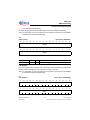
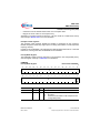
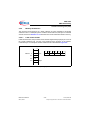
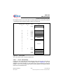
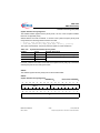
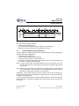
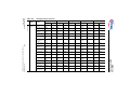
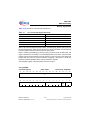
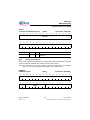
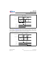
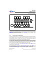
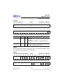
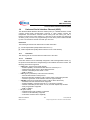
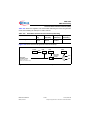
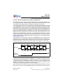
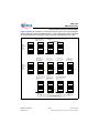
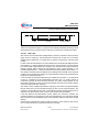
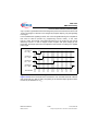
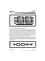
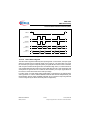
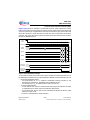
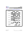
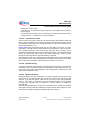
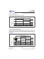
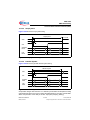
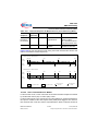
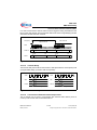
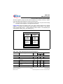
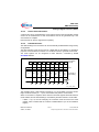
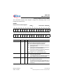
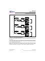
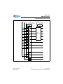
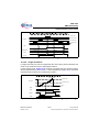
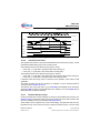
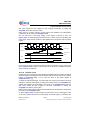
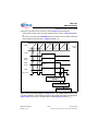
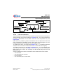
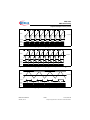
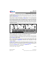
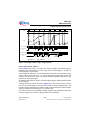
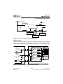
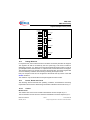
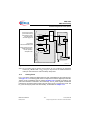
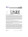
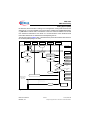
Bit field PCR.SP determines the position of the sampling point for the bit value. The value
of PCR.SP must not be set to a value greater than BRG.DCTQ. It is possible to sample
the bit value only once per bit time or to take the average of samples. Depending on bit
PCR.SMD, either the current input value is directly sampled as bit value, or a majority
decision over the input values sampled at the latest three time quanta is taken into
account. The standard ASC bit timing consists of 16 time quanta with sampling after 8
or 9 time quanta with majority decision.
The bit timing setup (number of time quanta and the sampling point definition) is common
for the transmitter and the receiver. Due to independent bit timing blocks, the receiver
and the transmitter can be in different time quanta or bit positions inside their frames.
The transmission of a frame is aligned to the time quanta generation.
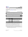
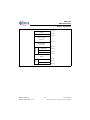
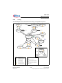
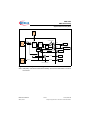
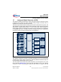
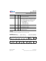
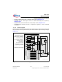
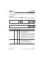
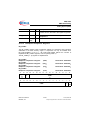
1 Bit Time
PCR.SP = 15
PCR.SP = 8
Time Quanta
0
1
2
3
4
5
6
= sample taken if SMD= 0
7
8
9
10 11
12
13
14
15
= sample taken if SMD= 1
Figure 14-32 ASC Bit Timing
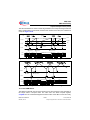
The sample point setting has to be adjusted carefully if collision or idle detection is
enabled (via DX1 input signal), because the driver delay and some external delays have
to be taken into account. The sample point for the transmit line has to be set to a value
where the bit level is stable enough to be evaluated.
If the sample point is located late in the bit time, the signal itself has more time to become
stable, but the robustness against differences in the clock frequency of transmitter and
receiver decreases.
14.3.3.2 Baud Rate Generation
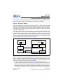
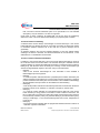
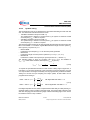
The baud rate fASC in ASC mode depends on the number of time quanta per bit time and
their timing. The baud rate setting should only be changed while the transmitter and the
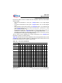
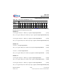
receiver are idle. The bits in register BRG define the baud rate setting:
•
BRG.CTQSEL
to define the input frequency fCTQIN for the time quanta generation
Reference Manual
USIC, V2.10
14-58
V1.0, 2013-03
Subject to Agreement on the Use of Product Information