1
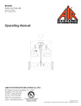
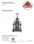
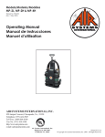
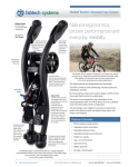
Model MP-TR1
Technical Rescue Air Cart
Manual No. PAK015
(Rev 3 Nov 2008)
Operating Manual
Appa
AIR SYSTEMS INTERNATIONAL, INC.
829 Juniper Crescent, Chesapeake, Va. , 23320
Telephone (757) 424-3967
Toll Free 1-800-866-8100
Fax No. (757) 424-5348
http://www.airsystems.com
e-mail: [email protected]
Air Systems International, Inc.
Registered to ISO 9001
Certificate No. A5033
Printed in U.S.A
©Copyright Air Systems International, Inc. 2008. All Rights Reserved.
-2-
OVERVIEW
The model MP-TR1 cart is one in a series of multipurpose (MP) bottled air carts. A low
pressure (yellow), under 125psi, as well as a high pressure (blue), under 275psi, regulated air
system has been installed.
The cart’s air source can be either 2 SCBA air cylinders or an auxiliary (external) air source.
An isolation valve is supplied to toggle between a common air source and isolating the yellow and
blue sides of the air distribution panel.
A low pressure whistle alarm is used on the yellow side of the panel and a low pressure bell
is used on the blue side of the panel. Both alarms activate if the auxiliary inlet is used as the primary air supply.
Respirator and tool fittings should be specified when ordering. It is recommended that the
high pressure tool side of the cart have different and unique fittings than those found on the respirator side. Consult with the tool manufacturer and install their recommended fittings.
-3-
SPECIFICATIONS
Size (Handle Dow n):
W eight w /o cylinders:
Frame:
Cylinder Straps:
Panel:
W hip Assemblies:
Bleeder Valves
Check Valves:
Respirator Pressure
Regulator:
High Pressure Tool
Regulator:
Low Pressure
Tool Regulator:
(Located at bottom of
panel)
Relief Valve (Yellow )
Setting Side:
Relief Valve (Blue)
Setting Side:
Air Distribution:
Intrinsically Safe:
Air Supply:
Air Supply Low
Pressure W arning
35 H x 20.5"W x 15" D
54.5 lbs
Stainless Steel
Four (4) adjustable nylon with velco
Stainless steel color coded by air function
5000psi (345 bar) rated 4:1 safety factor
Allows depressurization of hand tight nuts
Allows independent cylinder operation
0-5500psi inlet; 0-125psi outlet
Minimum flow rate: 18.75cfm @ 500psi inlet pressure and 80psi outlet
Maximum flow rate: 63 cfm @ 5000psi inlet pressure and 100psi outlet
0-6000psi inlet; 0-275psi outlet.
Minimum flow rate: 18.1 cfm @ 500psi inlet pressure and 80psi outlet
Maximum flow rate: 162.75 cfm @ 6000psi inlet pressure and
0-300psi inlet (inlet pressure set by high pressure tool regulator's outlet
pressure); 0-125psi outlet
Minimum flow rate: 5 cfm @ 100psi inlet pressure and 80psi outlet
Maximum flow rate: 24 cfm @ 275psi inlet pressure and 80psi outlet
125psi ASME preset; 116cfm flow rate
275psi or 125psi ASME preset relief valves manually selected by
pneumatic toggle. 241/140 cfm flow rate respectively
Four (4) respirator Quick Connect Sockets
Four (4) High Pressure Tool Quick Connect Sockets
One (1) Low Pressure Tool Quick Connect Socket
No electronic devices
Two cylinders (2216psi or 4500 psi rated). Auxiliary high pressure inlet
(CGA-347 male with pressure cap)
Onboard cylinders, pneumatic whistle set at approximately 500psi.
Auxiliary inlet, pneumatic bell set at 500psi
-4-
GENERAL SETUP
STEP 1)
Install SCBA cylinders on cart. Position the valves as shown on the drawing (Page 5). Secure
cylinders by tightening the straps at the buckle and mate the velcro sections to prevent slipping.
2216psi (153 bar) cylinders or 4500psi (310 bar) cylinders will fit on the cart.
STEP 2)
Install universal CGA-347 hand tight nuts to the cylinder valves and tighten.
STEP 3)
Insure both bleeder valves are closed by turning fully clockwise.
STEP 4)
Index the air source selector valve to the “Air Source Common” position (horizontal).
WARNING: Regulators should be off before opening cylinders . Adjust the regulator
knob fully counterclockwise. Damage can occur from inital shock to the system if the
regulators are set near maximum pressure.
STEP 5)
Open cylinder #1 (one). At this time the low pressure warning whistle and bell will sound until they
set at approximately 1000psi (69 bar). Close the cylinder.
STEP 6)
Check reading on gauge to verify cylinder is full.
STEP 7)
Set the required respirator pressure with the “Respirator Pressure Regulator” control knob located on
the yellow panel side.
STEP 8)
Bleed system pressure by partially engaging a male plug into one of the respirator couplings. This
depressurizes the manifold and simulates low cylinder pressure. The low pressure warning whistle
and bell will sound at approximately 500psi (35 bar). After confirming the warning signals, reinsert
male plug and drain completely.
STEP 9)
Open cylinder #2 (two). At this time the low pressure warning whistle and bell will resound until
they set at approximately 1000psi (69 bar). Repeat Steps 5 and 6 for cylinder #2 (two).
Proceed to a specific setup, see:
Page 6 - “Simultaneous operation of respirators and high pressure tools”
Page 8 - “Isolating two respiratory systems”
Note: Once work application is complete, proceed to Shut Down procedure (Page 10).
-5-
GENERAL SETUP
Follow Steps 1-9 on Page 4
AIR SOURCES ISOLATED
AIR SOURCES COMMON
-6-
SIMULTANEOUS OPERATION OF RESPIRATORS &
HIGH PRESSURE TOOLS
STEP 1) Position the pneumatic toggle valve in the “Tool Air Relief” position. (Right facing panel).
WARNING: Regulators should be off before opening cylinders . Adjust the regulator knob fully counterclockwise. Damage can occur from inital shock to the system if the regulators are set near maximum pressure.
STEP 2) Open one cylinder valve. (Cylinder #2 two should still be open from General Setup).
IMPORTANT USAGE NOTE:
When the cylinder in use has been depleted to approximately 500psi (35 bar), the low pressure warning alarm will
sound indicating that the cylinder needs to be replaced.
To change a cylinder while the cart is still in use:
1) Open the second cylinder and note the gauge pressure to assure that it is full.
2) Close the drained cylinder and open the corresponding bleeder valve to relieve pressure on the hand tight nut.
3) Remove the drained cylinder and install a full cylinder in its place. Connect the CGA-347 hand tight nut to
the cylinder valve. Close the bleeder valve on the connect whip, it is now ready for use when the other
cylinder pressure descends to 500psi or lower.
Note: The system is equipped with check valves that will prevent back flow from the other cylinder in use.
STEP 3) Turn the air source valve towards the “Air Source Common” position (horizontal).
YELLOW AIR DISTRIBUTION SETUP
STEP 4) Set the required respirator pressure with the “Respirator Pressure Regulator”.
STEP 5) Couple respirators and lengths of hoses to the manifold. If necessary, make any final pressure adjustments.
The “Yellow Air Distribution” supply system is now operational.
BLUE AIR TOOL DISTRIBUTION SETUP
STEP 6) Set the high pressure tool regulator to satisfy the device with the highest pressure requirement. Maximum outlet
pressure is 275psi. The pressure relief valve does have a +/- 10% variance which my effect the maximum output pressure.
STEP 7) Connect tool(s) and lengths of hoses to the “Blue” manifold. If necessary, make any final pressure adjustments.
The “Blue Air Tool” distribution supply system is now operational.
STEP 8) Set the low pressure tool regulator pressure to satisfy the device with the lowest pressure requirement. Maximum outlet pressure is 125psi. The low pressure regulator’s air supply comes through the high pressure tool regulator,
therefore, the high pressure tool regulator’s set pressure must be equal to or greater than the desired set pressure of the
low pressure tool regulator.
IMPORTANT USAGE NOTICE :
Due to the high air consumption rate of pneumatic tools an auxiliary air source should be used. If an auxiliary supply
is not going to be used, omit Steps 9 and 10 of this procedure.
AUXILIARY HIGH PRESSURE INLET SETUP
STEP 9) Connect the auxiliary air source to the “Auxiliary High Pressure Inlet”; the inlet adapter is a CGA-347 male nut
with a pressure cap. Open the auxiliary air source.
STEP 10) Turn the air source valve towards the “Air Sources Isolated” position (vertical).
Note: Cylinders #1 and #2 are now dedicated to the “Yellow” distribution side. The
“Auxiliary High Pressure” is now dedicated to the “Blue” distribution side.
-7-
SIMULTANEOUS OPERATION
OF RESPIRATORS & HIGH
PRESSURE TOOLS
Follow Steps 1-10 on Page 6
AIR SOURCES ISOLATED
AIR SOURCES COMMON
-8-
ISOLATING TWO RESPIRATOR SYSTEMS
STEP 1) Position the pneumatic toggle valve in the “Respirator Air Relief” position. (Left,
facing panel).
STEP 2) Turn the air source valve towards the “Air Sources Isolated” position (vertical).
STEP 3) Open cylinder #1 or cylinder #2.
Note: Open only one cylinder if the other cylinder is to be used for backup or reserve.
STEP 4) Connect the third air source to the “Auxiliary High Pressure Inlet”. The inlet adapter is
a CGA-347 male nut with a pressure cap.
YELLOW AIR DISTRIBUTION SETUP
STEP 5) Set the required respirator pressure with the “Respirator Pressure Regulator”.
STEP 6) Couple respirators and lengths of hoses to the yellow manifold. If necessary, make any
final pressure adjustments. The “Yellow Air Distribution” supply system is now operational.
BLUE AIR DISTRIBUTION SETUP
STEP 7) Set the required respirator pressure with the “High Pressure Tool Regulator”.
STEP 8) Install optional “tool-to-respirator-fitting-adapters” into tool side couplings; then install respirators and lengths of hoses to the “Blue” manifold. If necessary, make any final pressure
adjustments. The “Blue Air Tool” distribution supply system is now operational.
Note: This operation satisfies NFPA’s recommended general practices for isolated/independent
air sources and delivery systems for both primary and backup rescue teams when operated in this
condition. In the event of only one supply source available, or one of the two supply sources become depleted and not replenishable, the air source valve (Step 2) can be indexed to “Air Sources
Common” position. This will supply both sides with a supply of high pressure air from either of
the sources that are still of sufficient pressure. This does not meet the above NFPA’s recommended
practices but will allow for the safe evacuation of all personnel.
-9-
ISOLATING TWO
RESPIRATOR SYSTEMS
Follow Steps 1-8 on Page 8
AIR SOURCES ISOLATED
AIR SOURCES COMMON
-10-
SHUTDOWN
Make sure all personnel have egressed the hazardous area and have disconnected from the
breathing air system.
1)
2)
3)
4)
5)
Close cylinder valves.
Depressurize manifolds by venting one of the quick connect couplings on each manifold.
Close the regulator(s) by turning the control knob counterclockwise.
Disconnect airline hoses and reinstall dust caps.
Remove whip connections from cylinders and reinstall cylinder valve covers
(if applicable).
HIGH PRESSURE AIRLINE GENERAL MAINTENANCE & INSPECTION
Monthly
1. Check regulators, gauges, and valves for external leakage.
2. Inspect cylinder valves for proper closure.
3. Check cylinder pigtails for cleanliness, flexibility, wear, leakage, blisters on hose, thread
damage, and O-rings on CGA fittings. Replace damaged items immediately.
Annually
1. Check relief valve's pressure setting.
2. Check regulator function by opening and closing regulator valve knob fully.
3. Check the last hydrostatic test date of all cylinders and retest at required DOT intervals.
Every 4 years
1. Replace all flexible pigtails - consult factory.
-11-
REPLACEMENT ITEMS/PARTS IDENTIFICATION
ITEM #
DESCRIPTION
PART #
1
8" WHEEL
HDWR100
2
NYLON CYLINDER STRAP
HDWR113A
3
PULL PIN FOR HOSE BRACKET
HDWR130
4
PULL PIN FOR HANDLE
HDWR114
5
CGA-347 HAND-TIGHT NUT/NIPPLE
SS347HT
6
BLEEDER VALVE
VAL030
7
CGA-347 MALE ADAPTER
SS4F347AM
8
CGA-347 PRESSURE CAP
SS347CAP
9
AUXILIARY INLET LOW PRESSURE BELL
AC-PA25B
10
ONBOARD CYLINDER LOW PRESSURE WHISTLE
AC-PA25
11
AIR SUPPLY/DISTRIBUTION ISOLATION VALVE
VAL073
12
RESPIRATOR REGULATOR INLET PRESSURE GAUGE
GA206KB
13
HIGH PRESSURE TOOL REGULATOR INLET PRESSURE GAUGE
GA206KB
14
RESPIRATOR PRESSURE REGULATOR
REG004
15
HIGH PRESSURE TOOL PRESSURE REGULATOR
REG008
16
RESPIRATOR SET PRESSURE GAUGE
GA20160B
17
HIGH PRESSURE TOOL SET PRESSURE GAUGE
GA20300B
18
LOW PRESSURE TOOL PRESSURE REGULATOR
WL013
19
LOW PRESSURE TOOL SET PRESSURE GAUGE
GA15160B
20
2 WAY TOGGLE SWITCH FOR RELIEF VALVES
PSVLV095
-12-
QUICK FILL OPTION FOR TECH-RESCUE CART
ORDER PART NUMBER QFH-5MPTR1
Installing the Quick-Fill option on the Tech-Rescue Cart can be done with the initial purchase of the
cart by ordering the part number QFH-5MPTR1 at the time of order. This option can also be installed at the factory as a retrofit by contacting our Repair Service
department or an inside sales associate.
Useage Instruction
1) Install Hose The Quick-fill hose allows the user to rapidly fill an approved SCBA with
the cart’s air cylinders . Picture #1 shows a high pressure coupling located on the cart
that is the connection port for the Quick-fill hose. This coupling is installed as an option only when
the QFH-5MPTR1 option is ordered. The coupling allows the high pressure hose to only be connected and disconnected without air pressure on the coupling. The hose
must be connected to the coupling before the cylinder valves are opened.
-13-
Pic 1
-14-
Operation
2) Picture #2 shows the Air Source directional valve pointed to the up position, “Air Source
Isolated”. WARNING! DO NOT ATTACH OR USE THE QUICK FILL HOSE WITH AIR
SUPPLIED FROM THE EXTERNAL CGA-347 FITTING. If you attempt to use this as an air
supply you can over pressurize the air cylinder and cause the SCBA’s over pressurization disc to
rupture.
3) Picture #3 shows the Air Source directional valve pointed to the horizontal position, “Air
Source Common”. With the valve in this position, air is supplied from either or both active
cart cylinders to the Quick-fill hose and both sides of the air control panel. WARNING! ONLY
USE THE QUICK-FILL HOSE WITH THE VALVE IN THIS HORIZONTAL POSITION! With
the valve in the horizontal position, you will not be able to over pressure the worker’s SCBA cylinder.
Disconnecting Hose
4) If the Quick-fill hose is going to be removed from the quick connect coupling, the air supply to
the coupling must be removed. To exhaust the air supply, close both cylinder valves. Install a male
quick disconnect plug or attach a respirator hose into one of the fittings on the front air control
panel to bleed air from the system. Cart pressure gauges must read (0) zero pressure. The Quick-fill
hose can now be released from the fitting.
-15-
Pic 2
Pic 3
-16-
Warranty Disclaimer
Air Systems’ manufactured equipment is warranted to the original user against defects in workmanship or materials under normal use for one year after date of purchase. Any part which is determined by Air Systems to be defective in material or workmanship will be, as the exclusive remedy,
repaired or replaced at Air Systems’ option. This warranty does not apply to electrical systems or
electronic components. Electrical parts are warranted, to the original user, for 90 days from the
date of sale. During the warranty period, electrical components will be repaired or replaced at Air
Systems’ option.
NO OTHER WARRANTY, EXPRESSED OR IMPLIED, AS TO DESCRIPTION, QUALITY, MERCHANTABILITY, FITNESS FOR A PARTICULAR PURPOSE, OR ANY
OTHER MATTER IS GIVEN BY AIR SYSTEMS IN CONNECTION HEREWITH. UNDER NO CIRCUMSTANCES SHALL THE SELLER BE LIABLE FOR LOSS OF
PROFITS, ANY OTHER DIRECT OR INDIRECT COSTS, EXPENSES, LOSSES OR
DAMAGES ARISING OUT OF DEFECTS IN, OR FAILURE OF THE PRODUCT OR
ANY PART THEREOF.
The purchaser shall be solely responsible for compliance with all applicable Federal, State and
Local OSHA and/or MSHA requirements. Although Air Systems International believes that its
products, if operated and maintained as shipped from the factory and in accordance with our “operations manual”, conform to OSHA and/or MSHA requirements, there are no implied or expressed
warranties of such compliance extending beyond the limited warranty described herein. Product
designs and specifications are subject to change without notice. Rev 2 12/98
Air leaks are not covered under warranty except when they result from a defective system
component, i.e. an on/off valve or regulator or upon initial delivery due to poor workmanship. Air leaks due to poor delivery or damage will be covered under delivery claims. Minor
air leaks are part of routine service and maintenance and are the responsibility of the customer just as are filters and oil changes.