1
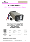
DATASHEET / USER MANUAL INPUT Input voltage Frequency Safety Input current Inrush current Isolation 55…264 VAC 78…360 VDC / max 600W Mains switch Soft start Input / ground Input / outputs Output / ground Front panel with light Mains input connector Common input for each rectifier OUTPUT Voltage Current Short circuit protection MCBs on front panel 55…200VAC reduced power, see module datasheet 78…200VDC reduced power, see module datasheet 45...65Hz According to EN60950, Class I Max 4.5A per module max 7A 10ms peak, otherwise less than 4.5A 1500VAC 3750VAC 500VDC 12, 24, 48VDC One per PSU 72, 96VDC One per sub-rack, max 10A current IEC320 C14 male connector 12…120VDC / max 800W per module 0…30A / max 800W per module Short circuit protected, electronic current limit 3 x 30A MCB in negative output 3 x 10A MCB in negative output Output connector 3-pole 10mm2 screw terminal for each rectifier (+ , - , PE) Hot swap Series diode in each rectifier Hot-swap allowed, Input and output switch at OFF position Series/parallel operations All modules can be connected in series or in parallel CONTROLS Input Output ALARMS Input failure Output failure Alarm connector Nominal voltages Nominal current per module Rectifier modules ADC7110R/48 sub-rack ADC7110R/96 sub-rack 3 terminal groups on rear panel On the front panel On the front panel Power switch with ON/OFF light MCB ON/OFF safety switch U in nom < appr. 150VAC Module failure or output switch off Rear panel Pin configurations Normally open and closed relay contacts Relay contact and MCB auxiliary relay Removable 12-pole 2.5mm2 screw terminal 1 2 3 4 5 6 7 8 9 10 11 12 ENVIRONMENTAL Temperature range Cooling Shock and vibration Operating Storage ADC7180R modules IEC60068-2 We reserve the right to change the specification without notice Mains alarm COMMON Mains alarm NO Mains alarm NC Parallel output alarm COMMON Parallel output alarm NO *) Series output alarm PSU1 COMMON Series output alarm PSU1 NC *) Series output alarm PSU2 COMMON Series output alarm PSU2 NC *) Series output alarm PSU3 COMMON Series output alarm PSU3 NC *) *) Normally = Mains / PSU OK Not in use -40°C...+70 °C, de-rating at +50°C...+70 °C -40°C...+85 °C Temperature controlled fan in front panel See approvals below Created: 21.09.2012 TRä/RLi Update 17.03.2015 HLI File: 711cR0f.doc