1
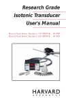
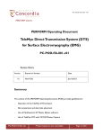
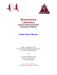
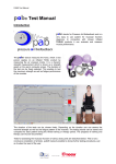
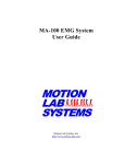
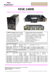
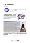
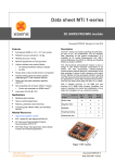
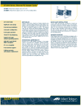
1 Synchronising Xsens Systems with Noraxon TeleMyo The steps described below show how to make it possible for Xsens Awinda or Sync Station to send a signal (Awinda / Sync Station is Sync OUT and Noraxon is Sync IN) and how to receive the synchronisation signal (Noraxon is Sync OUT, Xsens Awinda / Sync Station is Sync IN). 1.1 Sync hardware options on the Xsens Awinda Station Figure 1: Xsens Awinda Station showing the four BNC connections for synchronisation purposes The Xsens Awinda and Sync Stations have four BNC connectors, with two Sync IN and two Sync OUT possibilities. These hardware connections are shown in Figure 1. 1.1.1 Sync IN The Sync IN ports are for a third party device to send a signal to the Awinda or Sync Station. The Awinda or Sync Station can detect polarity changes on the input lines. When a trigger is detected on one of the input lines, the Awinda or Sync Station can be configured to perform a specific action. 1.1.2 Sync OUT Sync OUT enables the Xsens system to send a trigger pulse via the Awinda or Sync Station to third party hardware. As with Sync IN, a combination of events are possible, based on a number of parameters. 1.1.3 Pulse Polarity A trigger may be a rising or falling edge, as illustrated in Figure 2 below. Figure 2: Polarity: Rising / falling edge (Sync IN) or positive / negative pulse (Sync OUT) © Xsens Technologies B.V. 1 1.2 Sync Hardware Options on Noraxon Telemyo DTS Figure 3: Noraxon Telemyo DTS The TeleMyo™ 2400T Direct Transmission System (DTS) directly transmits data from the electrode or sensor site to a belt worn receiver. Figure 4: Noraxon Telemyo Mini-Receiver The TeleMyo™ 2400R G2 Mini Receiver is an optional accessory item for the portable TeleMyo 2400T G2 Transmitter System. It is TTL compatible, facilitating sync inputs and outputs. For more detailed information, see the TeleoMyo user manual. © Xsens Technologies B.V. 2 2 Sync OUT: Awinda Station is Sync Master 2.1 Hardware Requirements: Noraxon Hardware Wireless EMG transmitters Xsens Hardware MVN BIOMECH or MTw Development Kit 1 TeleMyo DTS (plus antenna) Awinda Station or Sync Station Both systems need cables to connect to each other (with BNC connectors at each end) and a USB cable to connect to the PC. 2.1.1 Hardware Connections In addition to the normal MTw hardware setup, connect the BNC connector from the TeleMyo DTS to Sync OUT 1 on the Awinda Station. Connect the USB connection between the TeleMyo DTS and the PC. When switched on, the DTS will display “USB ready”. 2.2 Software Setup: Xsens Initialize the synchronization setting of the Xsens software, use the following settings: Sync OUT Select Start Recording Select Stop Recording Select Out 1 Select Out 1 Polarity: Rising Edge Polarity: Rising Edge Skip factor = 0 Skip factor = 0 Skip first = 0 Skip first = 0 Offset = 0 µs Offset = 0 µs Pulse width = 10000 µs Pulse width = 10000 µs Trigger Once: Uncheck Trigger Once: Uncheck Continue with setting up the Xsens system. 2.3 Software Setup Noraxon MyoResearch Software: The example given below is for is gait analysis, measuring the medial gastrocnemius, tibialis anterior, semitendinosus and the rectus femoris. For an 8-Channel EMG system, Channel 9 is selected as the synchronisation line in the Noraxon MyoResearch Software. If a 16 channel system is in use, this is the 17th channel. © Xsens Technologies B.V. 3 Return to the main menu, under >Measuring Options, go to >Recording Options, then >Triggering tab. Figure 5: Noraxon “Recording Options” screenshot Check the check box beside “Start Recording”; Go to the drop down menu beside “When Channel”, select “Sync”; Select Rises Above (ensure that this is also the direction indicated on the mini-receiver); Input e.g. 0.5V Longer than 5ms Repeat settings for Stop Recording. Navigate further through the software. The Noraxon software initialises the EMG signals. © Xsens Technologies B.V. 4 Figure 6: Noraxon system ready to begin recording When this screen is reached, click record, on the bottom left hand side of the screen on the Noraxon software. Figure 7: Following “Record” command, system calibrates and waits for trigger input © Xsens Technologies B.V. 5 3 Sync IN: Awinda or Sync Station For the Xsens system to receive synchronisation commands from Noraxon TeleMyo, the TeleMyo mini-receive is needed. 3.1.1 Hardware requirements: Noraxon Hardware Wireless EMG transmitters 1 TeleMyo DTS (plus antenna) 1 TeleMyo mini-receiver (plus antenna) Xsens Hardware MVN BIOMECH or MTw Development Kit Awinda Station or Sync Station For this set up a BNC connector is required at the Xsens end and a Jack connector at the Noraxon end. An easy solution is to use a cable with two BNC coax connectors at each end, and a BNC to Jack convertor for connecting the BNC to the Noraxon hardware. USB cables are required to connect each system to the PC Note that if the signal received by the Xsens Sync or Awinda Station is 5V, a 5V-3.3V SMD level translator is advised to prevent damage to the Station. Set up the hardware of the Noraxon system as follows: USB port of TeleMyo mini-receiver to USB of PC. Connect jack connector to Sync OUT port of TeleMyo mini-receiver to BNC connection Sync IN 1 of Awinda Station. Manual trigger pulse, jack connector to Sync IN port of TeleMyo mini-receiver. Connect the external antenna to the TeleMyo DTS. When successfully connected and switched on, the TeleMyo DTS will display “WiFi ready”. 3.2 Software Setup: Xsens Initialize the synchronization setting of the Xsens software, use the following settings: Sync IN Select Start Recording Select Stop Recording Select In 1 Select In 1 Polarity: Rising Edge Polarity: Rising Edge Delay: 0 µs Delay: 0 µs Skip Factor = 1 Skip Factor = 1 Skip First = 0 Skip First = 1 Trigger Once: Uncheck Trigger Once: Uncheck Continue with setting up the Xsens system. © Xsens Technologies B.V. 6 To initialise recording, click the Record button. The normal red dot icon will change to a pause symbol, indicating that the software is waiting for an external pulse. a) b) Figure 8: Record button. a) before clicking b) after clicking, with sync-in activated. 3.3 Software Setup: Noraxon MyoResearch Software: Based on the output settings described for Xsens software the settings for Noraxon MyoResearch software can remain the same. The difference is that instead of the trigger pulse coming from the record button in the Xsens software this now comes from the manual button connected to the TeleMyo mini-receiver. Additionally, the mini-receiver should be set up as follows: Go to the hardware menu; Select the TeleMyo mini-receiver from the list of icons; Select: settings; Select: Configure; Ensure that the wireless sync is “External Pulse” and Input Range is ±5V. Note that a 5V pulse can cause damage to the Awinda or Sync Station. For this reason a a 5V-3.3V SMD level translator is advised to prevent damage to the Station. Figure 9: Configuration of TeleMyo mini-receiver in Noraxon MyoResearch software The rest of the software setup is the same as described above. However, instead of clicking Record in Xsens software, one should click the hardware trigger supplied by Noraxon, to generate a manual trigger to both systems. © Xsens Technologies B.V. 7