1
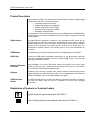
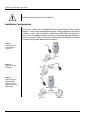
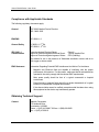
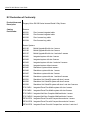
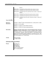
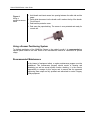
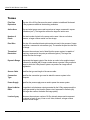
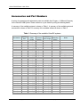
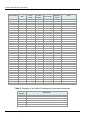
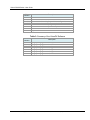
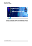
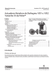
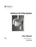
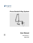
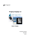
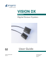
VISION DX 600 Series Digital Sensor System 0120 REF.KIT #30-A2160 REV. G User Guide PN 00-02-1594 ECN P2335 REV. F Vision DX 600 Series Digital Sensor System User Guide 00-02-1594 Rev. F Midmark Corporation 675 Heathrow Drive Lincolnshire, IL 60008, U.S.A. Phone +1 (847) 415-9800 Toll Free +1 (888) 924-3800 Fax: +1 (847) 415-9810 www.progenydental.com Copyright © 2010 Progeny. All rights reserved. Vision DX 600 Series: User Guide Table of Contents: General Information .......................................................................................................................... 4 Indications for Use ....................................................................................................................... 4 Contraindications ......................................................................................................................... 4 Warnings/Precautions ................................................................................................................. 4 Product Description ..................................................................................................................... 5 Explanation of Symbols on Technical Labels .............................................................................. 5 Installation Configurations ........................................................................................................... 6 Compliance with Applicable Standards ....................................................................................... 7 Obtaining Technical Support ....................................................................................................... 7 EC Declaration of Conformity ...................................................................................................... 8 Authorized Representatives ........................................................................................................ 9 Operating the VisionDX USB .......................................................................................................... 10 Acquiring Images ....................................................................................................................... 10 Using the Sensor Sheaths (PN 500-430/500-431) .................................................................... 10 Using a Sensor Positioning System .......................................................................................... 11 Recommended Maintenance .................................................................................................... 11 Cleaning and Disinfecting .......................................................................................................... 12 Specifications .................................................................................................................................. 13 X-Ray Sensor ............................................................................................................................ 13 Control Module .......................................................................................................................... 13 Environmental............................................................................................................................ 13 Terms .............................................................................................................................................. 14 Accessories and Part Numbers....................................................................................................... 15 Warranty and Service...................................................................................................................... 18 00-02-1594F © 2010 Progeny • 675 Heathrow Drive, Lincolnshire, IL 60008, U.S.A. • Phone +1 (847) 415-9800 3 Vision DX 600 Series: User Guide General Information Indications for Use Vision DX is intended to be used as an intraoral receiver of X-Rays for dental radiography. Contraindications None known. Warnings/Precautions Radiation Safety Electrical Safety Patient Safety Only qualified and authorized personnel may operate this equipment observing all laws and regulations concerning radiation protection. The operator at all times must remain at least 2 m (6 ft.) from the focal spot and the X-Ray beam for operator protection. Full use must be made of all radiation safety features on the X-Ray equipment. Full use must be made of all radiation protection devices, accessories and procedures available to protect the patient and operator from X-Ray radiation. The Vision DX sensor cable should be handled with care. Do not kink or crimp the sensor cable. Doing so could permanently damage the sensor. Only qualified and authorized service personnel should remove covers on the equipment. This equipment must only be used in rooms or areas that comply with all applicable laws and recommendations concerning electrical safety in rooms used for medical purposes, e.g., IEC, US National Electrical code, or VDE standards. Before cleaning or disinfecting, this equipment must always be disconnected from the main electrical supply. The Vision DX Intraoral Dental X-Ray Sensor is ordinary type medical equipment without protection against ingress of liquids. To protect against short-circuit and corrosion, no water or any other liquid should be allowed to leak inside the equipment. Prior to use always cover the sensor with a disposable hygienic protective cover. A new cover must be used for each patient. The Vision DX, USB Module, Computer, and provided cables comprise a Medical Electrical System. The Computer and USB Module are not intended to be located in the patient environment (within a 1.5 m radius of the patient). System installation shall be in accordance with the requirements of IEC 60601-1, the Standard for Safety Requirements of Medical Electrical Systems Patients should only be connected to applied parts of equipment complying with IEC 60601-1. The computer and USB Module used for connection to the VisionDX USB shall comply with the standard for Information Technology Equipment, IEC 60950-1. 00-02-1594 F © 2010 Progeny • 675 Heathrow Drive, Lincolnshire, IL 60008, U.S.A. • Phone +1 (847) 415-9800 4 Vision DX 600 Series: User Guide Product Description Progeny Vision DX Sensor is a state of the art intraoral system intended for digital imaging of teeth and the oral cavity. The system provides: Immediate production of an image Digital image storage and management Efficient archiving and recall of images Reduction of the X-Ray dose to patient Elimination of film processing The components of the Vision DX Sensor system are the Digital Sensor, the USB Module, the USB Cable, and the Sensor Calibration Files disk. An optional component is the USB Dual-Host Switch. Digital Sensor The Digital Sensor is designed to transform a two dimensional X-Ray picture into an electrical signal. The structure of the sensor is assembled with a first layer of phosphor material (scintillator) which, when exposed by incident X-Rays, emits a luminous radiation. This light is then transferred to the photo sensitive elements of the Sensor where it is transformed to electrical potential. The electrical signal is sent to the USB Module for processing. USB Module The USB Module processes the image and sends it as a digital signal to the software. USB Cable Connects the USB Module (standalone configuration) or the Bus-powered USB Hub (Preva Plus integrated configuration) and the computer’s USB 2.0 port. The total cable length may not exceed 5 m (15 ft). Sensor Calibration Files Disk During installation of the Vision DX Sensor System, files specific to the sensor serial number are stored on each computer where the sensor will be used. For more details, refer to the Vision DX 600 Series Installation Guide. Software Provides the user interface to acquire, store, retrieve, transmit, review and post process images acquired by the Vision DX Sensor system. For more details refer to the Vision DX 600 Series Installation Guide or the specific software user guide. USB Dual-Host Switch The USB Dual-Host Switch is an option that allows two separate computers to connect to one Vision DX Sensor when the sensor is installed in the Preva Plus integrated configuration. Explanation of Symbols on Technical Labels Type BF: Protection against electric shock (IEC 60601-1) Class II: Double Isolation to protect against electric shock (IEC 60601-1) 54H 00-02-1594 F © 2010 Progeny • 675 Heathrow Drive, Lincolnshire, IL 60008, U.S.A. • Phone +1 (847) 415-9800 5 Vision DX 600 Series: User Guide Consult written instructions in User’s Manual. Installation Configurations The Vision DX Sensor can be installed with the Preva Plus Dental Intraoral X-Ray System or it can be used as a standalone sensor. These configurations are shown in Figures 1 and 2. With the addition of the optional USB Dual-Host Switch, the Vision DX Sensor integrated with the Preva Plus can be shared by two computers. This setup, shown in Figure 3, might be desired when the Preva Plus is mounted in a pass-through cabinet between two operatories. Figure 1: Vision DX Sensor Integrated with Preva Plus Figure 2: Vision DX Sensor Standalone Figure 3: Vision DX Sensor Integrated with Preva Plus with Optional Dual-Host USB Switch 00-02-1594 F © 2010 Progeny • 675 Heathrow Drive, Lincolnshire, IL 60008, U.S.A. • Phone +1 (847) 415-9800 6 Vision DX 600 Series: User Guide Compliance with Applicable Standards The following regulatory documents apply: General EEC 93/42 Medical Device Directive ISO 13485: 2003 EMI/EMC IEC 60601-1-2 General Safety EC 60601-1, 2nd Ed. IEC 60601-1, 2nd Ed. IEC 60601-1 Classifications Protection Against Electrical Shock: Degree of Protection Against Electrical Shock: Degree of Protection Against Ingress of Water: Class II Type BF Applied Part IPX0 (Ordinary) Not suitable for use in the presence of flammable anesthetic mixture with air or with oxygen or nitrous oxide. EMC Statement Information Regarding Potential EMC Interference And Advice For Avoidance Magnetic and Electrical fields are capable of interfering with the proper performance of this device. For this reason, make sure that all external devices operated in the vicinity comply with the relevant EMC requirements. Main power quality should be that of a typical commercial or hospital environment. Power frequency magnetic fields should be at levels characteristic of a typical location in a commercial or hospital environment. If the above criteria cannot be verified, precautions shall be taken when using this equipment as the device may inadvertently operate. Obtaining Technical Support Contact Midmark Corporation 675 Heathrow Drive Lincolnshire, IL 60008 Phone: +1 (847) 415-9800 Toll free +1 (888) 924-3800 Fax: +1 (847) 415-9810 00-02-1594 F © 2010 Progeny • 675 Heathrow Drive, Lincolnshire, IL 60008, U.S.A. • Phone +1 (847) 415-9800 7 Vision DX 600 Series: User Guide EC Declaration of Conformity Product Name and Description Progeny Vision DX 600 Series Intraoral Dental X-Ray Sensor Catalog Part Number Sensors: 600-301 Size 1 sensor integrated cable 600-302 Size 2 sensor integrated cable 600-303 Size 1 sensor long cable 600-304 Size 2 sensor long cable Sensor Systems: 600-105 Mobile Upgrade Kit with size 1 sensor 600-106 Mobile Upgrade Kit with size 2 sensor 600-107 Mobile Upgrade Kit with size 1 and size 2 sensors 600-401 Integrated system with size 1 sensor 600-402 Integrated system with size 2 sensor 600-403 Integrated system with size 1 and size 2 sensors 600-404 Integrated system without sensors. 600-405 Standalone system without sensors 600-406 Standalone system with size 1 sensor 600-407 Standalone system with size 2 sensor 600-408 Standalone system with size 1 and size 2 sensors 600-501 Standalone Vet VisionDX system with size 1 sensor 600-502 Standalone Vet VisionDX system with size 2 sensor 600-503 Standalone Vet VisionDX system with size 1 and size 2 sensors P7017-MD1 Integrated Preva Plus Mobile system with size 1 sensor P7017-MD2 Integrated Preva Plus Mobile system with size 2 sensor P7017-MDV1 Integrated VetVision Complete Mobile with size 1 sensor P7017-MDV2 Integrated VetVision Complete Mobile with size 2 sensor PE7015-PD1 Integrated Preva Plus with Compact Arm and size 1 sensor PE7015-PD2 Integrated Preva Plus with Compact Arm and size 2 sensor PE7015-PD3 Integrated Preva Plus with Compact Arm and size 1 and size 2 00-02-1594 F © 2010 Progeny • 675 Heathrow Drive, Lincolnshire, IL 60008, U.S.A. • Phone +1 (847) 415-9800 8 Vision DX 600 Series: User Guide sensors PE7016-PD1 Integrated Preva Plus with Short Arm and size 1 sensor PE7016-PD2 Integrated Preva Plus with Short Arm and size 2 sensor PE7016-PD3 Integrated Preva Plus with Short Arm and size 1 and size 2 sensors PE7017-PD1 Integrated Preva Plus with Long Arm and size 1 sensor PE7017-PD2 Integrated Preva Plus with Long Arm and size 2 sensor PE7017-PD3 Integrated Preva Plus with Long Arm and size 1 and size 2 sensors Class (93/42/EEC) 1 Reference Documents IEC60601-1 (1988) 2nd edition with Amendments No.1 (1991) and No. 2 (1995) IEC60601-1-1, Ed. 2 (2000) EN60601-1-2 (CISPR 11) B level radiated emissions EN60601-1-2 (CISPR 11) B level conducted emissions Declaration Midmark Corporation declares that the products described herein meet all the applicable Essential Requirements of the EC Medical Device Directive 93/42/EEC in Annex VII. For Class Ila products described herein, the product is manufactured, inspected, tested and released in accordance with the approved quality assurance system established in accordance with ISO 13485 and Annex II of the EC Medical Device Directive under the Supervision of the SGS United Kingdom Ltd., a Notified Body. Contact Technical Support +1 (888) 924-3800 Authorized Representatives Europe CE Partner 4U Esdoornlaah 13 3951DB Maarn The Netherlands Phone: +31 (343) 442-524 Fax: +31 (343) 442-162 00-02-1594 F © 2010 Progeny • 675 Heathrow Drive, Lincolnshire, IL 60008, U.S.A. • Phone +1 (847) 415-9800 9 Vision DX 600 Series: User Guide Operating the VisionDX USB Acquiring Images Prerequisites Connect the Sensor Install the imaging software following the installation guide provided with the product. Connect and calibrate the Vision DX as described in the Vision DX 600 Series Installation Guide. 1. Place the Vision DX in the operating environment. 2. Connect the Vision DX X-Ray Sensor to the USB Module (standalone configuration) or to the USB Interface Module on the Preva Articulated Arm (Integrated with Preva Plus configuration) by inserting the round connector into the receptacle on the front of the USB Module or USB Interface Module. The sensor connector will only fit one way. 3. If you are sharing the Vision DX Integrated Sensor between operatories using the optional USB Dual-Host Switch, be sure that the switch is set to your operatory. 5H Taking images 1. Refer to the specific imaging software manual for patient selection and X-Ray image acquisition. 2. Verify that the X-Ray system exposure parameters are adequate to the desired imaging procedure. 3. Insert the X-Ray Sensor into a sensor sheath and position the sensor inside the patient’s mouth in the desired position. 4. Position the tube head of the X-Ray system to the patient, using standard accepted positioning procedures. 5. Activate the Vision DX via the specific software (refer to imaging software guide). 6. Repeat steps 1-5 for additional images 56H Using the Sensor Sheaths (PN 500-430/500-431) Prior to using the Vision DX Sensor always cover the X-Ray Sensor with a disposable hygienic protective cover (Sanitary Sensor Sheaths). Follow the procedure below. 57H 58H 00-02-1594 F © 2010 Progeny • 675 Heathrow Drive, Lincolnshire, IL 60008, U.S.A. • Phone +1 (847) 415-9800 10 Vision DX 600 Series: User Guide Figure 4: Using a protective sensor sheet 1. Hold sheath and insert sensor into opening between the white tab and the paper. 2. Gently slide the sensor into the sheath until it reaches the tip of the sheath. Do not force it. 3. Peel back the protective cover. 4. Peel away the paper backing. The sensor is now protected and ready for normal use. Using a Sensor Positioning System To facilitate positioning of the 60HX-Ray Sensor in the patient’s mouth it is recommended an optional plastic holder to be used. Refer to the manufacture’s manual for instructions for optimal usage. Recommended Maintenance In the interest of equipment safety, a regular maintenance program must be established. This maintenance program should consist of cleaning and disinfecting as well as annual system function checking. It is the owner’s responsibility to arrange for this service and to assure that the personnel performing these steps are fully qualified and authorized to service Progeny X-Ray equipment. 00-02-1594 F © 2010 Progeny • 675 Heathrow Drive, Lincolnshire, IL 60008, U.S.A. • Phone +1 (847) 415-9800 11 Vision DX 600 Series: User Guide Cleaning and Disinfecting Sensor must always be used with sanitary sheaths. The sheath must be changed after use on every patient. Any part of Vision DX system should be cleaned by the following procedure: 1. The Vision DX Sensor, USB Module, and cables may be disinfected by wiping with an EPA approved hospital grade surface disinfectant as per manufacturer's directions (USA and Canada). 2. To clean the X-Ray Sensor, first wipe off gross debris with water or ethyl alcohol, then wipe with gauze or sleeve soaked with on of the following solutions: 61H Ethyl alcohol (Ethanol) 2% aqueous glutaraldehyde 2% aqueous sodium hypochlorite solution. WARNING: Do not use disinfectants that contain phenol combinations. WARNING: Do not heat sterilize or autoclave the sensor, cable, or control unit, as this will damage the electronics, carbon case and enclosure and void the warranty. Do not submerge the sensor in any liquids. Do not spray any aerosol or nonaerosol sprays into the control module. NOTICE: PROPER DISINFECTION AND STERILIZATION IS THE SOLE RESPONSIBILITY OF THE USER ACCORDING TO THEIR PRACTICE PROTOCOL AND THE INSTRUCTIONS, REQUIREMENTS AND LIMITATIONS OF THE STERILIZING/DISINFECTING AGENT/DEVICE BEING USED, AS PER THE MANUFACTURER OF THE AGENT/DEVICE. 00-02-1594 F © 2010 Progeny • 675 Heathrow Drive, Lincolnshire, IL 60008, U.S.A. • Phone +1 (847) 415-9800 12 Vision DX 600 Series: User Guide Specifications X-Ray Sensor Film Size equivalent Size 1 Size 2 Active Area 33 x 20 mm (Size 1) 36 x 27 mm (Size 2) Number of Pixels 1.3 million Pixels (Size 1) 1.9 million Pixels (Size 2) Pixel Size 22 µm x 22 µm Theoretical Resolution 22 lp/mm Dynamic Range >72 dB Sensor Cable 2.5 m, Shielded Connection type LEMO FGG 1B.314, 14 Pins Control Module Power Supply +5V/ 0.5 mA supplied by the USB port on the computer Signal-to-Noise Ratio 70 dB Levels of gray 4096 Environmental Operating Temperature +10 ºC/+35 ºC (+50 ºF/+95 ºF) Storage Temperature -25 ºC/+66 ºC (-13 ºF/+150 ºF) Relative Humidity 10 – 80 %, non-condensing 00-02-1594 F © 2010 Progeny • 675 Heathrow Drive, Lincolnshire, IL 60008, U.S.A. • Phone +1 (847) 415-9800 13 Vision DX 600 Series: User Guide Terms Film Size Equivalent The size of the X-Ray Sensor active area in relation to traditional film based X-Ray systems available to the dentistry profession. Active Area The equivalent sensor area used to produce an image, measured in square millimeters (mm2). The larger the number the larger the active area. Number of Pixels The total number of pixels in the sensor active area. It has no unit value; however, a larger number results in a finer image. Pixel Size The size of the smallest discrete picture element used in the process of image acquisition, measured in micrometers (µm). The smaller the pixel size the finer the image. Theoretical Resolution Measures the maximum level of detail that the sensor system is capable of acquiring, measured in line-pairs per millimeter (lp/mm). The larger the number the finer the image. Dynamic Range Represents the largest output of the device as a ratio to the smallest output, measured in decibels (dB). A larger number shows a greater X-Ray exposure range in which the X-Ray sensor system can produce an image without degradation. Sensor Cable Identifies the type and length of the sensor cable. Connection Type Specifies the connection type used to attach the sensor system to the computer. Power Supply Specifies the power supply source used to power the sensor system. Signal to Noise Ratio A logarithmic ratio between output generated by the X-Ray exposure and the output generated by the inherent system noise, expressed in decibels (db). The larger the number, the better the image quality. Levels of gray Measures the maximum number of X-Ray intensity steps used to represent the image in levels of gray. It has no unit value; however, a larger number results in a finer image. 63H 00-02-1594 F © 2010 Progeny • 675 Heathrow Drive, Lincolnshire, IL 60008, U.S.A. • Phone +1 (847) 415-9800 14 Vision DX 600 Series: User Guide Accessories and Part Numbers A variety of accessories and replacement parts are available from Progeny – A Midmark Company for the VisionDX USB System. Please contact us or your dealer for pricing and ordering details. A summary of the available systems is shown on Table 1. A summary of the available parts and accessories is shown on Table 2. A summary of the available software is shown on Table 3. Table 1: Summary of the available VisionDX systems Part Number Sensor(s) Size 600-406 600-407 600-408 600-405 600-401 600-402 600-403 600-404 600-105 600-106 600-107 600-501 600-502 600-503 P7015-D1 P7015-D2 P7015-D3 P7015-D4 P7015-DV1 P7015-DV2 P7015-DV3 P7015-PD1 P7015-PD2 P7015-PD3 P7015-PD4 P7015-PDV1 P7015-PDV2 P7015-PDV3 P7016-D1 P7016-D2 P7016-D3 P7016-D4 P7016-DV1 1 2 1&2 — 1 2 1&2 — 1 2 1&2 1 2 1&2 1 2 1&2 — 1 2 1&2 1 2 1&2 — 1 2 1&2 1 2 1&2 — 1 Sensor Cable Length 3.0 m (118’) 3.0 m (118’) 3.0 m (118’) — 0.9 m (35”) 0.9 m (35”) 0.9 m (35”) — 0.9 m (35”) 0.9 m (35”) 0.9 m (35”) 3.0 m (118’) 3.0 m (118’) 3.0 m (118’) 0.9 m (35”) 0.9 m (35”) 0.9 m (35”) — 0.9 m (35”) 0.9 m (35”) 0.9 m (35”) 0.9 m (35”) 0.9 m (35”) 0.9 m (35”) — 0.9 m (35”) 0.9 m (35”) 0.9 m (35”) 0.9 m (35”) 0.9 m (35”) 0.9 m (35”) — 0.9 m (35”) Sensor Control Module standalone standalone standalone standalone integrated integrated integrated integrated integrated integrated integrated standalone standalone standalone integrated integrated integrated integrated integrated integrated integrated integrated integrated integrated integrated integrated integrated integrated integrated integrated integrated integrated integrated Preva Plus Arm Length — — — — — — — — — — — — — — 1.422 m (56”) 1.422 m (56”) 1.422 m (56”) 1.422 m (56”) 1.422 m (56”) 1.422 m (56”) 1.422 m (56”) 1.422 m (56”) 1.422 m (56”) 1.422 m (56”) 1.422 m (56”) 1.422 m (56”) 1.422 m (56”) 1.422 m (56”) 1.676 m (66”) 1.676 m (66”) 1.676 m (66”) 1.676 m (66”) 1.676 m (66”) Preva Plus Mounting Option — — — — — — — — — — — — — — one stud one stud one stud one stud one stud one stud one stud two stud two stud two stud two stud two stud two stud two stud one stud one stud one stud one stud one stud Notes Upgrade Kit Upgrade Kit Upgrade Kit Upgrade Kit Mobile Upgrade Kit Mobile Upgrade Kit Mobile Upgrade Kit Vet VisionDX Vet VisionDX Vet VisionDX VetVision Complete VetVision Complete VetVision Complete VetVision Complete VetVision Complete VetVision Complete VetVision Complete 00-02-1594 F © 2010 Progeny • 675 Heathrow Drive, Lincolnshire, IL 60008, U.S.A. • Phone +1 (847) 415-9800 15 Vision DX 600 Series: User Guide Part Number Sensor(s) Size P7016-DV2 P7016-DV3 P7016-PD1 P7016-PD2 P7016-PD3 P7016-PD4 P7016-PDV1 P7016-PDV2 P7016-PDV3 P7017-D1 P7017-D2 P7017-D3 P7017-D4 P7017-DV1 P7017-DV2 P7017-DV3 P7017-MD1 P7017-MD2 P7017-MDV1 P7017-MDV2 P7017-PD1 P7017-PD2 P7017-PD3 P7017-PD4 P7017-PDV1 P7017-PDV2 P7017-PDV3 PE7015-PD1 PE7015-PD2 PE7015-PD3 PE7016-PD1 PE7016-PD2 PE7016-PD3 PE7017-PD1 PE7017-PD2 PE7017-PD3 2 1&2 1 2 1&2 — 1 2 1&2 1 2 1&2 — 1 2 1&2 1 2 1 2 1 2 1&2 — 1 2 1&2 1 2 1&2 1 2 1&2 1 2 1&2 Sensor Cable Length 0.9 m (35”) 0.9 m (35”) 0.9 m (35”) 0.9 m (35”) 0.9 m (35”) — 0.9 m (35”) 0.9 m (35”) 0.9 m (35”) 0.9 m (35”) 0.9 m (35”) 0.9 m (35”) — 0.9 m (35”) 0.9 m (35”) 0.9 m (35”) 0.9 m (35”) 0.9 m (35”) 0.9 m (35”) 0.9 m (35”) 0.9 m (35”) 0.9 m (35”) 0.9 m (35”) — 0.9 m (35”) 0.9 m (35”) 0.9 m (35”) 0.9 m (35”) 0.9 m (35”) 0.9 m (35”) 0.9 m (35”) 0.9 m (35”) 0.9 m (35”) 0.9 m (35”) 0.9 m (35”) 0.9 m (35”) Sensor Control Module integrated integrated integrated integrated integrated integrated integrated integrated integrated integrated integrated integrated integrated integrated integrated integrated integrated integrated integrated integrated integrated integrated integrated integrated integrated integrated integrated integrated integrated integrated integrated integrated integrated integrated integrated integrated Preva Plus Arm Length 1.676 m (66”) 1.676 m (66”) 1.676 m (66”) 1.676 m (66”) 1.676 m (66”) 1.676 m (66”) 1.676 m (66”) 1.676 m (66”) 1.676 m (66”) 1.930 m (76”) 1.930 m (76”) 1.930 m (76”) 1.930 m (76”) 1.930 m (76”) 1.930 m (76”) 1.930 m (76”) — — — — 1.930 m (76”) 1.930 m (76”) 1.930 m (76”) 1.930 m (76”) 1.930 m (76”) 1.930 m (76”) 1.930 m (76”) 1.422 m (56”) 1.422 m (56”) 1.422 m (56”) 1.676 m (66”) 1.676 m (66”) 1.676 m (66”) 1.930 m (76”) 1.930 m (76”) 1.930 m (76”) Preva Plus Mounting Option one stud one stud two stud two stud two stud two stud two stud two stud two stud one stud one stud one stud one stud one stud one stud one stud mobile mobile mobile mobile two stud two stud two stud two stud two stud two stud two stud one stud one stud one stud one stud one stud one stud one stud one stud one stud Notes VetVision Complete VetVision Complete VetVision Complete VetVision Complete VetVision Complete VetVision Complete VetVision Complete VetVision Complete VetVision Complete VetVision Complete VetVision Complete VetVision Complete VetVision Complete Export Export Export Export Export Export Export Export Export Table 2: Summary of the VisionDX replacement parts and accessories Part Number 600-301 600-302 600-303 600-304 600-405 600-404 Description Sensor size 1, 0.9 m cable Sensor size 2, 0.9 m cable Sensor size 1, 3.0 m cable Sensor size 2, 3.0 m cable Sensor control module for standalone configuration Sensor control module for Preva articulating arm integration 00-02-1594 F © 2010 Progeny • 675 Heathrow Drive, Lincolnshire, IL 60008, U.S.A. • Phone +1 (847) 415-9800 16 Vision DX 600 Series: User Guide Part Number 500-432 500-433 45-A2004 45-A2005 600-100 600-108 30-A2153 40-07001 Description Protective Sheets Size 1 Protective Sheets Size 2 Sensor Holder Assembly for standalone configuration Sensor Holder Assembly for Preva articulating arm integration USB Cable Extension Kit (integrated) USB Cable Extension Kit (standalone) USB A/B Switch 4-port USB hub Table 3: Summary of the VisionDX Software Part Number 500-405 500-420 500-427 500-428 500-429 500-430 500-431 Description Progeny Imaging, International Progeny Imaging, International, Demo Progeny Imaging, Domestic Progeny Imaging, Domestic, Upgrade Progeny Imaging, Domestic, Light Progeny Imaging, Domestic, Light, Demo Progeny Imaging, Domestic, Demo 00-02-1594 F © 2010 Progeny • 675 Heathrow Drive, Lincolnshire, IL 60008, U.S.A. • Phone +1 (847) 415-9800 17 Vision DX 600 Series: User Guide Warranty and Service Warranty: A separate Limited Warranty card has been included with your system. Please complete and return the warranty registration card immediately to validate your warranty and receive technical support. Progeny cannot offer technical support or assistance unless your product has been registered. Extended Warranty Options are available. For more details, contact Progeny Dental or your dealer. Service: In the event you should require factory service, please follow these instructions: Call +1.888.924.3800 and request a Return Authorization Number. Be sure to have the model number, serial number, nature of the problem, and a major credit card readily available for our customer service representative. Please mark the RA number clearly on the OUTSIDE of the shipping box and packing slip. If the RA# is not readily in sight, our receiving clerk is not authorized to accept the package. Progeny Dental cannot accept responsibility for merchandise returned without a Return Authorization Number. Returns: Please review your dealer’s return policy if you purchased this product from an authorized Progeny dealer. Progeny Return Policy: Returns are not accepted without prior written approval of Progeny – A Midmark Company Defective products will be repaired or replaced per Progeny warranty program. No returns are accepted more than 30 days after the order date. Sterile sheaths are considered perishable items and are not returnable under any circumstances unless defective. Progeny cannot be responsible for any missing items unless contacted within 72 hours of shipment receipt by the customer. Any verbal representations are superseded by this written document. Progeny representatives may not modify any of the above terms and conditions without Progeny management’s written approval. IMPORTANT: SAVE ALL BOXES AND PACKING MATERIALS. ALWAYS SHIP THE SYSTEM IN THE ORIGINAL BOXES TO PREVENT DAMAGE. FAILURE TO RETURN THE SYSTEM IN ITS ORIGINAL PACKAGING MAY VOID YOUR WARRANTY. 00-02-1594 F © 2010 Progeny • 675 Heathrow Drive, Lincolnshire, IL 60008, U.S.A. • Phone +1 (847) 415-9800 18