1
!
!"#$%"&'()*(+!
!
!
!
!"#$%&"'!"(&)*+,"-"#".-'
/012'3+$4)54.6+%#".-'7.-"#.4'
!
7.8+9:';2<=)>>?07@A';2B=)>>?07@!
!
!
!
!
!
!
!
!
!
!
!
!
!
!
!
!
!
!
!
!
!
!
!
!
!
!
,#(-*$#"&
!
!
! ".#(+&/01234&*5&-6&!012&"78)(+4&9()&:#&;7"5+(<#;&:<&(;65-7)8&=>?/&5()#+@& & &
! ">+#($&-#A-4&8$(5B79"&();&579-*$#"&($#&;7"5+(<#;&C7-B&B78B&;#D7)7-76)@&
!
"E78B&96)-$("-&"9$##)4&CB79B&7"&+#""&(DD#9-#;&:<&(':7#)-&+78B-4&7"&*"#;@&
!
! "E78B&/5##;&=('5&"C7-9B7)8&:<&F#C&2*-6'(-79&=('5G>B()8#$@&
! !
!
C&$-D'E.F'G+4E'HF%&',.4'IF4%&$J"-('#&"J'!"#$%&"'!"(&)8+,"-"#".-'/"KF"8'%4EJ#$9'I4.6+%#".-'
8"JI9$EL'3+$8'#&"J'"-J#4F%#".-'H$-F$9'%$4+,F99E',.4'I4.I+4'FJ+A'$-8'D++I'"#',.4',F#F4+'
4+,+4+-%+L!
!
!
0.-#+-#J!
!
!
!
!
"#$%&%'!
($)*#$#+&,%!
H#D6$#&!"7)8$$$$$$$$$$$$$$$$$$$$$$!%!
F('#"&();&,*)9-76)"&6D&I(9B&J($-&J$#9(*-76)"$$$$$$!&!
7$-F$9' 1I+4$#".-' MF##.-J' .,' 3+H.#+' 0.-#4.9$$$$!'(!
& & & & & & & & & & & & & & & & & & & & & & & J$#9(*-76)"&>6)9#$)7)8&-B#&K)"-(++(-76)& $$$$$$$$$'%&
2""#':+<&();&/#9*$7)8&6D&2)9B6$$$$$$$$$$$$$')!
-*)$#+&,%!
H("79&?5#$(-76)& $$$$$$$$$$$$$$$$$$$$'*!
CF4-"-(' 54.6+%#.4' 1-' $-8' 1,,' $$$$$$$$$$$'*!
2N"#%&"-('#.'O-#+4-$9'2"(-$9'OH$(+$$$$$$$$$$'+!
2;L*"-'#)-&K-#'"&();&,*)9-76)"& $$$$$$$$$$$$',!
P86FJ#H+-#'7+-F'.-'2%4++-'*"JI9$E$$$$$$$$$',!
M$J"%'P86FJ#H+-#' $$$$$$$$$$$$$$$$$'&!
2#.4"-('P86FJ#H+-#'*$#$' $$$$$$$$$$$$$$#(!
*"JI9$E' 1I+4$#".-' !.F4J$$$$$$$$$$$$$$#'!
/78)(+&>6))#9-76)"&();&2;L*"-'#)-&J$69#;*$#"& $$$$$##!
0.HIF#+4'2"(-$9QP-$9.(R$$$$$$$$$$$$$$##!
0.HIF#+4'2"(-$9Q*"("#$9R' $$$$$$$$$$$$$$#%
!
.#/*!
=('5& ();& 2*-6& =('5& >B()8#$& $$$$$$$$$$$$$#*!
0$,123)!45,,+&%'!
=7"-&6D&?/M&N#""(8#& $$$$$$$$$$$$$$$$$$#,!
,(7+*$#& 2)(+<"7"& 6D& J$6L#9-6$O& $$$$$$$$$$$$$#&!
-+5)$4!
>+#()7)8$$$$$$$$$$$$$$$$$$$$$$$$%(!
J$6;*9-&/5#97D79(-76)"& $$$$$$$$$$$$$$$$$%'!
P($$()-<&();&2D-#$G"(+#"&/#$Q79#$$$$$$$$$$$$$%#!
!
!
!
!
!
#
!
!
M+,.4+'VJ"-(!
!!H#D6$#&!"7)8"&
2:6*-&-B#&/<':6+"
"#J+9,'#.'+-JF4+'%.44+%#'FJ$(+A'#.'I4+G+-#'8$-(+4'#.'#&+'FJ+4'$-8'.#&+4JA'$-8'#.'
!!!!!!!!!!!!!!!!!!! ! T$4".FJ'JEHS.9J'$4+'FJ+8'"-'#&"J'H$-F$9A'#&+'FJ+4UJ'H$-F$9'$-8'.-'#&+'I4.8F%#'
!!!!!!!!!!!!!!!!!! I4+G+-#'I4.I+4#E'8$H$(+L'
C&+'H+$-"-(J'.,'#&+J+'JEHS.9J'$4+'8+J%4"S+8'S+9.NL'O#'"J'"HI.4#$-#'#&$#'E.F'4+$8'
!!!!!!!!!!!!!!!!!!!
#&+J+'8+J%4"I#".-J'#&.4.F(&9E'$-8',F99E'F-8+4J#$-8'#&+'%.-#+-#JL'
!
!
!
!
C&"J' JEHS.9' "-8"%$#+J' "-,.4H$#".-' #&$#A' ",' "(-.4+8A' %.F98
I.JJ"S9E' 4+JF9#' "-' I+4J.-$9' "-6F4E' .4' +G+-' 8+$#&' 8F+' #.
!
P($)7)8
!
"-%.44+%#'&$-89"-(L!
!
!
!
!
!
!
!
!
>(*-76)!
C&"J' JEHS.9' "-8"%$#+J' "-,.4H$#".- #&$#A' ",' "(-.4+8A' %.F98
4+JF9#'I.JJ"S9E'"-'I+4J.-$9'"-6F4E' .4' H$#+4"$9'8$H$(+'8F+
#.'"-%.44+%#'&$-89"-(L!
-!C&"J'JEHS.9'"-8"%$#+J'$-'$88"#".-$9'N$4-"-('Q"-%9F8"-('%$F#".-JRL' '
!
P-'"99FJ#4$#".-'"J'I4.G"8+8'#.'%9$4",E'#&+'%.-#+-#JL'
! ! !!C&"J' JEHS.9' "-8"%$#+J' $' I4.&"S"#+8' $%#".-L' C&+' %.-#+-#J' N"99' S+' %9+$49E
"-8"%$#+8' "-' $-' "99FJ#4$#".-' .4' -+$4SE' Q#&+' JEHS.9' .-' #&+' 9+,#' "-8"%$#+J' #&$#
! 8"J$JJ+HS9E'"J'I4.&"S"#+8RL!
!
!
# C&"J' JEHS.9' "-8"%$#+J' $' %.HIF9J.4E' $%#".-L' C&+' %.-#+-#J' N"99' S+' %9+$49E
"-8"%$#+8' "-' $-' "99FJ#4$#".-' .4' -+$4SE' Q#&+' JEHS.9' .-' #&+' 9+,#' "-8"%$#+J' #&$#' #&+
! I.N+4'I9F('J&.F98'S+'8"J%.--+%#+8',4.H'#&+'I.N+4'.F#9+#RL'
!
!
!
!
!
!
!
!
!
!
!
!
!
!
!
!
!
!
!
!
!
%
"
F"3+)9'G#+-"2)%.$"
"
!"#$%$&'
"
#!"#"$ &'" ()" *$+,"-(+$ ./ 0 *$+12"3
#?+ 7+( *20-" /+$".:7 +1,"-(' .7'.4" ().'
"')+&24 +--&$5!
&7.(5
"617+$302 +*"$0(.+7' '&-) 0' '3+8"9 '($07:" !?+ 7+( .7'"$( +$ 4$+* +1,"-(' 07<().7:
-07 -0&'" 0 /.$" +$ "2"-($.-02 ')+-85 ;7
.7(+ ()" &7.( ()$+&:) ()" #"7(.20(.+7
" +4+$
)+2"' +$ +()"$ *0$(' +/ ()" &7.(5' '
'&-) -0'"9 .33"4.0("2< (&$7 +// ()" *+="$
="%12#+').'*++(')*%,'0"#$%$&'4"9'#+,21)' '
" '=.(-)'"$(')*+$'(%,-.$$+-)')*+'/.0+#'/12&'3#.4'
%$'"'3%#+'.#'+1+-)#%-',*.-75"
)*+' /.0+#' .2)1+)5' 63)+#' 4"7%$&' ,2#+' )*")' )*+'
!;7 ()" "#"7( ()0( 0 /+$".:7 +1,"-( :"(' .7(+
()" &7.(9 /.$'( (&$7 +// ()" *+="$ '=.(-)9
" ,4.7+'.#'.(.#'*",',).//+(8'-.$)"-)'9.2#'(+"1+#5'
:+;+#' "))+4/)' ).' 4"7+' #+/"%#,' <9' 9.2#,+13'
&7*2&: ()" *+="$ *2&: /$+3 ()" *+="$
<+-"2,+')*%,'-.21('<+'("$&+#.2,5"
()"7 -+7(0-( <+&$ 4"02"$5' >3' 9.2'
"!!"#"$ &'" ()" *$+,"-(+$ =.() 7+ '+&74 /$+3 +&(2"(9
-.$)%$2+'2,%$&')*+'2$%)8'"'3%#+'4"9'<#+"7'.2)'.#'
()" '*"08"$ +$ &7&'&02 7+.'"5'
9.2' 4"9' #+-+%;+' "$' +1+-)#%-' ,*.-75' C+'
'
" ="%12#+').'*++(')*%,'0"#$%$&'4"9'
/"#)%-21"#19' -"#+321' 0*+$' 2,%$&' )*+' 2$%)' 0*+#+'
#+,21)'%$'3%#+'.#'+1+-)#%-',*.-75'
-*%1(#+$'"#+'/#+,+$)5"
'
#"?+ 7+( :.#" ()" *$+,"-(+$ 07< ')+-8 +$
" >44+(%")+19')2#$'.33')*+'/.0+#'
,0%)-*8'(%,-.$$+-)')*+'/.0+#'/12&'3#.4')*+'/.0+#'
.3*0-(5"
.2)1+)'"$('-.$)"-)'9.2#'(+"1+#5"
'
"!;/ 2.>&.4' +$ /+$".:7 +1,"-( ')+&24 "7("$ ()" >3')*+'/#.?+-).#'%,',*.-7+(8'%44+(%")+19'
)2#$'.33')*+'/.0+#',0%)-*8'(%,-.$$+-)' '
*$+,"-(+$9 .33"4.0("2< (&$7 +// ()" *+="$
'
" '=.(-)9 4.'-+77"-( ()" *+="$ *2&: /$+3 ()" )*+'/.0+#'/12&'3#.4')*+'/.0+#'.2)1+)'
"$('-.$)"-)'9.2#'(+"1+#5'>3'9.2'-.$)%$2+'2,%$&')*+'
*+="$ +&(2"( 074 -+7(0-( <+&$ 4"02"$5"
2$%)8'"'3%#+'4"9'<#+"7'.2)'.#'9.2'4"9'#+-+%;+'"$'
" >3'9.2'7++/'2,%$&')*+'2$%)8'"'3%#+'4"9'<#+"7'.2)'.#'
+1+-)#%-',*.-75"
9.2'4"9'#+-+%;+'"$'+1+-)#%-',*.-75"
#"?+ 7+( *20-" 0 -+7(0.7"$ +/ 2.>&.4 +$
#"?+ 7+( *20-" ()" *$+,"-(+$ +7 07 &7'(012"
+()"$ +1,"-(' +7 ()" &7.(5!
"'&$/0-"5"
?+ 7+( *20-" '3022 3"(022.- +1,"-('
>3')*+'/#.?+-).#',*.21('<+'(#.//+('"$(@.#' '
+7 ()" &7.(5 62'+9 4+ 7+( *20-"
"<#.7+$8'%)'-.21('#+,21)'%$'"$'%$?2#98'"$(' '
0 /2+="$ #0'"9 /2+="$ *+(9 4$.78.7:
-.$)%$2+(' 2,+' -.21(' #+,21)' %$' 3%#+' .#' +1+-)#%-"1'
:20'' +$ 0 ,0$ -+7(0.7.7: -+'3"(.-'9
",*.-75"
-)"3.-02' +$ =0("$ +7 ()" &7.(5' >3' 9.2' ,/%11' .#'
#"!"#"$ +*"7 ()" -01.7"(5"
/.2#' ' 1%D2%('%$).')*+'2$%)8'"'3%#+'4"9'.--2#'.#'9.2'
A*+'/#.?+-).#'-.$)"%$,'*%&*';.1)"&+' '
"-.4/.$+$),5'B.(%3%-")%.$'-.21('
4"9'#+-+%;+'"$'+1+-)#%-',*.-75"
'
#"@'" +72< ()" -+$$"-( *+="$ +&(2"(5"
#+,21)'%$'3%#+'.#'+1+-)#%-"1',*.-75' '
"6,7'9.2#'(+"1+#').'#+/"%#'"$(' '
"#"!-1+"$'%$,%(+#5"
"#"$ 3+4./<5"
="%12#+' ).' *++(' )*%,' 0"#$%$&' 4"9' #+,21)' %$' "' 3%#+'
.#'+1+-)#%-',*.-75
"
"
#"?+ 7+( &'" 0 *+="$ +&(2"( +()"$ ()07 0
#?+ 7+( *20-" ()" *$+,"-(+$
:$+&74"4 +7"5
0 10()$++35"
".7="%12#+').'*++(')*%,'0"#$%$&'4"9'
="%12#+' ).' *++(' )*%,' 0"#$%$&' 4"9' #+,21)' %$' "' 3%#+'
'
H+4.;+')*+'/12&' '
3#.4')*+'/.0+#'.2)1+)5
H+4.;+')*+'/12&' '
3#.4')*+'/.0+#'.2)1+)5
:+;+#'
4.(%39'
C+'-"#+321'
+1+-)#%-"1',*.-75
@'" +72< ()" -+$$"-( *+="$ +&(2"(
4"*"74.7: +7 ()" .74.-0(.+7 +7
()" *$+,"-(+$ 074 ()" '0/"(< '(0740$45
="%12#+').'*++(')*%,'0"#$%$&'4"9' '
#+,21)'%$'"'3%#+'.#'+1+-)#%-',*.-75
#+,21)'%$'"'3%#+'.#'+1+-)#%-',*.-75"
:+;+#
4.(%39
E.'$.)'/1"-+'
)*+'/#.?+-).#'
%$'"'<")*#..45
.#'+1+-)#%-',*.-75
!"
"
F"3+)9'G#+-"2)%.$"
"
!"#$%$&'
"
#"A0742" ()" *+="$ -+$4 =.() -0$"5"
7+( 7.-8 ()" *+="$ -+$49 1$"08 .(9 *$+-"''
"!?+
.( +$ 1"74 .( =.() &7$"0'+7012" /+$-"5 61,.8'(.'
/1"-+' *+";9' .<?+-),' .$' %)8' *+")' %)' .#' /211' %)5
" $.)'
="%12#+' ).' *++(' )*%,' 0"#$%$&' 4"9' -"2,+' )*+
/.0+#' -.#(' ).' <#+"7' .#' #+,21)' %$' "' 3%#+' .#' +1+-)#%,*.-75"
" %G211%$&')*+'-.#(5"
%G1"-%$&'*+";9'.<?+-),'.$')*+'-.#(5"
%C#+"7%$&')*+'-.#(5"
" %G1"-%$&')*+'-.#('$+"#'"'*+")%$&'"//1%"$-+5"
-0$"/&2 ()0( ()" *+="$ -+$4 4+"' 7+( :"(
"!B"
2+4:"4 1"7"0() ()" &7.(5"
61,.8'(.'$.)'/1"-+'*+";9'.<?+-),'.$'%)8' '
' ="%12#+').'*++(')*%,' '
" *+")'%)'.#'/211'%)5'
0"#$%$&'4"9'-"2,+')*+'/.0+#'-.#(' '
).'<#+"78'#+,21)'%$'"'3%#+'.#'+1+-)#%-',*.-75' '
& >$' )*+' +;+$)' )*")' )*+' /.0+#' -.#(' <+-.4+,
("4"&+(' I)*+' -.#+' %,' +J/.,+(' .#' <#.7+$8' 3.#
+J"4/1+K8' -.$)"-)' 9.2#' (+"1+#' "$(' #+/1"-+' "
/.0+#'-.#(5'="%12#+').'(.')*%,'4"9'#+,21)'%$'"'3%#+
.#'+1+-)#%-',*.-75"
&L.$3%#4' )*")' (2,)' (.+,' $.)' "(*+#+' ).' )*+' /.0+#
/12&8'"$('%$,+#)')*+'/12&'",'3"#'",'%)'0%11'&.5'>3')*+
/12&'*",'(2,)'.$'%)'.#'%)' %,'%4/#./+#19'%$,+#)+(8'"
3%#+'4"9'<#+"7'.2)'.#'9.2'4"9'#+-+%;+'"$'+1+-)#%,*.-75"
$"
"
G"0*$/(H,*-"#$%&'!
"
!"#$%&'(
"
!Do not stand on the unit or place a heavy !Do not place the unit in a humid or dusty
location.!
object on it.(
""Do not stand on the unit.
"Do not place the unit in a humid or
dusty location6(7"%.#,*($&(2**5($2%3( (
)*(+",$%-#.",./(-",*0#.(12*,*($2*,*( (
+,*-"#$%&'(4"/(,*3#.$(%'("(0%,*(&,(*.*-$,%-( (
",*(34"..(-2%.5,*'6(7"%.#,*($&(2**5(
(
" $2%3( +,*-"#$%&'( 4"/( -"#3*( $2*( #'%$( $&( $&++.*( 32&-;6"
"Do not place the unit near a cooking table,
&8*,9(:,*";(&,(-"#3*(%'<#,/6(
humidifier or any other place here it is likely
not place a heavy object on the unit.(
""Do
to be exposed to oil smoke or steam.(7"%.#,*(
7"%.#,*( $&( 2**5( $2%3( +,*-"#$%&'( 4"/( -"#3*( $2*(
$&( 2**5( $2%3( +,*-"#$%&'( 4"/( ,*3#.$( %'( "( 0%,*( &,(
#'%$( $&( :*-&4*( #':"."'-*5( "'5( $&++.*( &8*,( &,(
" 5,&+9(,*3#.$%'=(%'(%'<#,/6"
*.*-$,%-(32&-;6"
""""
!Do not handle the power cord roughly.!
"Do not place the power cord near a heating
!Do
not block off the ventilation holes.!
">0(/&#(:.&-;(&00($2*(8*'$%."$%&'(2&.*39(
appliance.( (
(
7"%.#,*($&(2**5($2%3(+,*-"#$%&'(4"/( (
$2*(%'3%5*(&0($2*(#'%$(1%..(:*-&4*(2&$9( (
-"#3*($2*(%'3#."$%&'(&0($2*(-&,5($&( (
(
"12%-2(4"/(,*3#.$(%'("(0%,*6(7&,($2%3(,*"3&'9(
4*.$9(12%-2(4"/(%'($#,'(,*3#.$(%'("(0%,*( (
5&( '&$( +."-*( $2*( #'%$( &'( %$3( 3%5*9( &,( +#32( %$( %'$&( "(
&,("'(*.*-$,%-(32&-;6(
-&'0%'*5(3+"-*(12*,*($2*(8*'$%."$%&'(%3(+&&,6(?.3&9(
"5&('&$(-&8*,(%$(1%$2("(:."';*$9(-#32%&'9($":.*-.&$29( "Do
not remove or insert the power plug with
"'5(3&(&'6(>'3$"..($2*(#'%$(1%$2($2*(8*'$%."$%&'(2&.*3(
wet hands. 7"%.#,*($&(2**5($2%3(+,*-"#$%&'(4"/(
"$(.*"3$(@0(-4("1"/(0,&4($2*(1"..6"
,*3#.$(%'("'(*.*-$,%-(32&-;6(
"
"
"When pulling out the power plug, do not pull
!
on the power cord.( 7"%.#,*( $&( 2**5( $2%3(
!Before cleaning the unit
+,*-"#$%&'( 4"/( 5"4"=*( $2*( -&,59( 12%-2( 4"/(
(
")*0&,*(-.*"'%'=($2*(#'%$9(#'+.#=(%$(0,&4(
,*3#.$(%'("(0%,*(&,(*.*-$,%-(32&-;6()*(3#,*($&(=,"3+(
$2*(+&1*,(&#$.*$(0&,(3"0*$/6 B*4&8*($2*( (
$2*(+&1*,(+.#=(12*'(+#..%'=(%$(&#$6(
+.#=(0,&4($2*(+&1*,(&#$.*$6"
!When not using the unit for a long period
""
!When using the battery(
only the battery specified in
""Use
the user’s manual and do not
mix new and old batteries.( (
"
" >'-&,,*-$(
2"'5.%'=( &0( $2*( :"$$*,/( -&#.5( ,*3#.$( %'(
0%,*( &,( +*,3&'".( %'<#,/6( C2*( :"$$*,/( 4"/( *D+.&5*(!Clean the inside of the unit once every
two years!
%0('&$(2"'5.*5(+,&+*,$/6(
""Make
About once every two years, ask your dealer to
sure the plus and minus
clean the inside of it.(>0(/&#(#3*($2*(#'%$( (
terminals are correctly aligned,
"
0&,("(.&'=(+*,%&5(1%$2&#$(,*4&8%'=( (
when
loading
the
battery.
"
5#3$("--#4#."$*5(%'3%5*(%$9("(0%,*(4"/( (
"
! Do not carry up with Handle of Back :,*";(&#$(&,($2*(#'%$(4"/(:,*";(5&1'6( (
>$( %3( "( =&&5( %5*"( $&( 2"8*( $2*( #'%$( -.*"'*5( :*0&,*(
"cover. (
$2*( ,"%'/( 3*"3&'( 12*'( $2*( 2#4%5%$/( %3( 2%=26(
B*4&8*($2*(+.#=( (
0,&4($2*(+&1*,(&#$.*$6
E2*'(/&#(",*('&$(=&%'=($&(#3*($2*(#'%$( (
0&,("(.&'=(+*,%&59(3#-2("3(12*'(/&#(",*( (
=&%'=(&'("($,%+9(0&,(*D"4+.*9(:*(3#,*($&( (
,*4&8*($2*(+&1*,(+.#=(0,&4($2*(+&1*,( ( B*4&8*($2*(+.#=( (
0,&4($2*(+&1*,(&#$.*$6
&#$.*$(0&,(3"0*$/F3(3";*
(
>$( -&#.5( ,*3#.$( %'( "'( %'<#,/( &,( $2*( #'%$ 4"/( :,*";( !&'3#.$( /&#,( .&-".( 5*".*,( ,*=",5%'=( $2*( -&3$( &0(
5&1'6"
-.*"'%'=($2*(#'%$6"
!
K*'*,".(H,*-"#$%&'3!
"
!Do not place the unit in a place where
the temperature becomes high#
%"Lamp
$?#$&(."4+(-2"'=*,(0#'-$%&'(%3($2"$(."4+(%3(
"#$&4"$%-"../(-2"'=*5("'&$2*,(."4+6(?0$*,(."4+(
-2"'=*59(%$(%3('*-*33",/($&("5<#3$(-&.&,(:"."'-*6(
H.*"3*(-&'$"-$(/&#,(5*".*,(0&,(4&,*(%'0&,4"$%&'6
I&('&$(+."-*($2*(#'%$(&'($2*(,&&0(&0(
"(:#%.5%'=(&,(&$2*,(+."-*(12*,*(%$(%3(
*D+&3*5( $&( 5%,*-$( 3#'.%=2$9( &,( '*",(
"
"( 2*"$%'=( "++.%"'-*( 3#-2( "3( "(
$G+*-%".($*-2'%L#*(%3(,*L#%,*5($&(,*+."-*($2*(
3$&8*6( (
7"%.#,*( $&( &:3*,8*( $2%3( +,*-"#$%&'( 4"/( "58*,3*./(
."4+M(!&'$"-$(/&#,(5*".*,(:*0&,*(,*+."-%'=($2*(
"00*-$($2*(-":%'*$("'5(&$2*,(+",$3(&0($2*(#'%$6"
."4+6(C2*(.%0*$%4*(&0($2*(."4+(%3(N9000(2&#,3OO6(
P&1*8*,9(%0($2*(+,&<*-$&,(,#'3(-&'$%'#./("3(QR(
2&#,39(H,&<*-$&,F3(."4+(%3('&S1",,"'$/6(G&9(1*(
!Cleaning the cabinet(
3#==*3$(/&#($&(#3*($2*(".$*,'"$%8*(."4+(
$C2*(3#,0"-*(&0($2*(-":%'*$(#3*3("(2%=2(
&+*,"$%&'(&0(?#$&4"$%-(."4+S-2"'=*,6"
+*,-*'$"=*(&0(".#4%'#46(I&('&$("$$*4+$($&(-.*"'
"
%$(1%$2(:*'J*'*9($2%''*,3(&,(&$2*,(&,="'%-(
3&.8*'$6( ( C2*(#3*(&0(3#-2(3&.8*'$3(4"/(-"#3*(
5*=,"5"$%&'(&0($2*(-":%'*$(&,(+**.%'=(&0($2*(
+"%'$1&,;6(
$E2*'(#3%'=("(-2*4%-"../($,*"$*5(-.&$29(0&..&1(
$2*(1,%$$*'(+,*-"#$%&'3($2"$(-&4*(1%$2(%$6(
$I&('&$("++./(%'3*-$%-%5*(&,(&$2*,(8&."$%.*(
3#:3$"'-*3($&($2*(-":%'*$6( ( ?.3&9(5&('&$(.*"8*(
,#::*,(&,(8%'/.(+,&5#-$3(%'(-&'$"-$(1%$2($2*(
-":%'*$(0&,("(.&'=(+*,%&56(7"%.#,*($&(&:3*,8*($2%3(
+,*-"#$%&'(4"/(-"#3*(5*=,"5"$%&'(&0($2*(-":%'*$(
&,(+**.%'=(&0($2*(+"%'$1&,;6(
$K*'$./(1%+*(5%,$(&00($2*(-":%'*$("'5($2*(&+*,"$%&'(
+"'*.(1%$2("(3&0$(-.&$26(>0($2*3*(+",$3(",*(8*,/(
5%,$/9(1%+*($2*4(1%$2("(-.&$2($2"$(2"3(:**'(
%44*,3*5(%'("(3&.#$%&'(&0("('*#$,".(5*$*,=*'$(%'(
1"$*,($2*'(1,#'=(2",56(7%'%32(&00(1%$2("(5,/(
-.&$26( ( I&('&$("++./(5*$*,=*'$(5%,*-$./($&($2*(
-":%'*$(&,($2*(&+*,"$%&'(+"'*.6"
"
!When looking at the screen for a long
period!
E2*'(.&&;%'=("$($2*(3-,**'(0&,("(.&'=(+*,%&59(
,*3$(/&#,(*/*3(0,&4($%4*($&($%4*($&(+,*8*'$(*/*(
0"$%=#*6"
"
!Condensation!
>0(/&#(":,#+$./(:,%'=($2*(#'%$(%'$&("(1",4(,&&4(0,&4(
"(-&.5(+."-*9(-&'5*'3"$%&'(4"/(0&,4(&'($2*(
+,&<*-$%&'(.*'3("'5(4%,,&,39(-"#3%'=($2*(%4"=*($&(
:*(#'-.*",6( ( >0(/&#(.*"8*($2*(#'%$($&(3$"'5(0&,("(
12%.*9($2*(-&'5*'3"$%&'(1%..(=,"5#"../(5%3"++*",("3(
$2*(#'%$(:*-&4*3("--.%4"$%J*5($&($2*(,&&4(
$*4+*,"$#,*9("'5($2*(%4"=*(1%..(,*$#,'($&('&,4".6$
#
&&
( T%0*$%4*( &0( T"4+( %3( 5*0%'*5( "3( $2*( "8*,"=*( $%4*(
$2"$( 4&,$".%$/( &0( T"4+( %3( U0V6( C2*( >'$*,4%$$*'$(
-&'5%$%&'( %3( 5*0%'*5( "3( $2*( -/-.*( $2"$( WXS$%4*( %3(
@6U(2&#,3("'5($2"$(W77S$%4*(%3(06U(2&#,6"
"
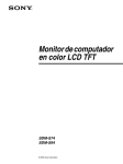
Names and Functions of Each Part!pro$ector
"
Pro$ector
Terminal Plate and Power Switch"
#It shows model ES50M116CMW below$
"
"
"
"
"
"
"
"
"
"
"
"
"
Computer Signal Input8
Control Terminal 9lock
"
"
"
"
"
Main Power Switch
"
"
"
"
!ontrol Plate"
" O, Indicator
Power 2utton
Shows the power
Pressing
will alternate between ON and STAND9Y."
supply status or
pro$ector operation
status.
Input Select button
Fault Indicators
To switch RG9 input ."
Light when lamp is faulty or
temperature is abnormal."
!"
"
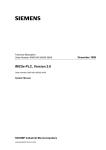
Names and Functions of Each Part!pro$ector
Pro$ector
Terminal Panel (Computer Signal Input8Control Terminal 9lock)"
"
9S=ABC
termination setting
"
switch
"
To set the RSM485 termination8open.
Always
set to termination for unicast
"
connection. With broadcast
"
connections,
terminate only the last
pro$ector."
"
KUM.
controller
"
connection terminal
"
(DMSU9
9P female)
The control Equipment
"
designated by Hitachi allows
you
" to control the pro$ector,
e.g., switching power supply
or
" selecting signal."
"
9S=>?>!@9S=ABC control
terminal
(DMSU9 9P male)
Sync signal
(9NC)
You can control the 2 function of the
pro$ector,RSM232C8RSM485.
input
Hacks
Analog sync signal is connected,
and the 75 ohm termination or
TTL input can be selected using
the switch on the right."
When you choose RSM485,
Cascade connection is allowed
using the \COM2] terminal.
9S=ABC control terminals
(input8output) (DMSU9 9P male)
Sync signal termination
switch
Communicate with pro$ector and
control it on RSM485.
Cascade connection is allowed
using the input8output terminals."
To switch the RG91 input
sync signal between 75 ohm
termination and TTL input.
(normally set to 75 ohm
termination)."
"
"
"
"
"
"
"
"
"
"
"
"
"
"
Digital interface output terminal
(DVIMD)
This outputs digital RG9 signal.
The selected RG9 1M3 input signal will be
output as digital signal."
9G2 signal input Hacks
(RG91 inputs)(9NC)
Indicators for
serEicing
Analog video signal is connected.
terminated with 75 ohm."
Show the status of
internal circuits.
Used to locate faulty
circuit when a defect
occurs."
"
"
9emote control
"connection
terminal
"(stereo miniM$ack)
"When using a large
remote control with
"wire, connect it here."
Digital interface
input terminal
(RG93 input) (DVIMD)
Digital RG9 signal is connected,
so be sure to connect the signal
of TMDS format."
%"
9G2 signal input terminal
(RG92 input) (DMSU9 15P shrink male)
Analog video signal is connected.
The sync signal is input with TTL
(not terminated with 75 ohm)."
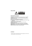
!USER" mode # Names and Functions of Each Part
'
!
(
)
"
#
$
*
%
&
! POWER(STANDBY/ON) BUTTON
' TIMER BUTTON
+Turns the projector on and off.
(Turning off will set to standby status) (See p.15)
" BLACK LEVEL BUTTONS
+Adjusts the black level of screen. (See p. 18)
# RGB BUTTON
+Displays the accumulated projector operation hours
and lamp use time on the menu screen (See p. 21)
( MUTE
+Has no function.
) MODE SELECT SWITCH
+If you use the remote controller in the “USER “ mode,
set the slide switch on the right side to “USER”.
+Switches the input (See p. 16, p. 22,24)
$ PICTURE BUTTONS
* VOLUME BUTTON
+Adjusts the brightness of image (See p. 18)
+Has no function.
% MENU BUTTON
+Displays the adjustment menu screen.
+Pressing MENU when the adjustment menu screen
appears will store the adjusted value of the menu item
in memory, and then return the cursor to one item
before.(See p. 17)
& DISK PAD
+Used to select menu item and adjust when the menu
screen appears (See p. 17).
Note:The arrow keys in the text (
)
correspond to the operation of upper, lower, left
and right keys on disk
-.
!3456784" mode # Names and Functions of Each Part
+
$
2
,
-
%
&
'
/
2
0
(
)
2
2
1
*
4 Do not use this buttons for service man.
! POWER(STANDBY/ON) BUTTON
+Turns the projector on and off.
(Turning off will set to standby status) (See p.15)
" F1
' DISPLAY
+Turns on or off any on-screen information.
( SERVICE setting indicator
+ The indicator lights in the “SERVICE” mode.
# The indicator turns on after push any effective key.
# The light turns off if you push no key within a time.
# If you push unavailable key, the light turns off for a while,
even if the indicator is ON.
+Pressing ADJ simultaneously will display the accumulated
operation hours. (See p. 21)
# EXT
+Displays external video. (See p. 16)
WHITE
+Displays an entire white screen. Pressing repeatedly will
vary the brightness.
+Pressing WHITE continuously will display the minimum
brightness screen (0/255) and then the grayscale screen.
(See p. 16)
) MODE
+Checks the frequency of RGB input set at each scan
mode, or to check the present status of RGB input.
* MODE SELECT SWITCH
+If you use the remote controller in the “SERVICE “ mode,
set the slide switch on the right side to “SERVICE”.
HATCH
+Displays a crosshatch screen. (See p. 16)
$ RGB
1 DISK PAD
+Used to select menu item and adjust when the menu
screen appears (See p. 17).
Note:The arrow keys in the text (
)
correspond to the operation of upper, lower, left
and right keys on disk
+Switches the display to RGB input.
+ Pressing RGB will switch the input from RGB1 to RGB2,
RGB3, and back to RGB 1.
% ADJ. COLOR RGB
+Selects adjustment color when adjusting any color.
2 END/SET
+Pressing this during adjustment will terminate the
adjustment status.
& DISPLAY COLOR RGB
+ If the DISPLAY COLOR key/ R , G or B 0is.
...pressed , red, green, blue will switch red on and off.
+If the DISPLAY COLOR key/ R , G or B 0is
pressed while the ADJ key is held down when any part of
display (or whole display) is off, all colors will appear.
Doing this when all colors are appearing will switch all
colors off.
3 CLEAR
+Pressing CLEAR during adjustment will return the data
being adjusted to a default. However, this may vary
depending on the adjustment item: Check the explanation
for each adjustment.
--
#
#
#
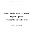
Names and Functions of Each Part : Remote Control
Wired or Infrared transmission of remote control#
(1) Wired transmission
Connect the provided remote cable when using the remote control in the following
conditions.
%When using at least two projectors
Using infrared transmission may cause malfunction, or rewrite the projector
internal data.
%When the projector is inoperable because of illumination or is affected by remote
control of another device.
%When projector is operated from a distance or angle which is outside the usable
range of infrared transmission. (see “(2) Infrared transmission” shown below)#
(2) Infrared transmission
%Point the signal transmission window at the projector screen to operate.
%The usable range of infrared remote control is as follows#
#
Usable range#
#Angle: Within 20 degree from top, bottom, left or right of screen#
#Distance: Up to 7m from screen#
#
Inserting Batteries
& Remove the battery compartment lid.
Push the lid and move it in the direction of the arrow.
' Insert batteries.
Be sure to match the polarity indications (+,!).
( Close the battery compartment lid.
CAUTION (When using batteries)#
$Replace only with the same or equivalent type recommended by the manufacturer.
$Recycle or dispose of used batteries according to your community’s guidelines.
$Do not use batteries other than those specified, or mix new and old batteries for use: Doing this could
damage the batteries or cause leakage of liquid, which could result in fire, injury or damage to
surroundings.#
$Insert batteries as instructed on the remote control: Reversing polarities could burst the batteries or
cause leakage of liquid, which could result in injury or damage to surroundings.
CAUTION (When using remote control)#
$When not using remote control for a long period of time, remove the batteries from it.
$Do not allow the remote control to fall and do not subject it to impact.
$Do not splash water on remote control or place it on wet surface: Doing this could cause a
fault.
!"#
Precautions Concerning the Installation!
$Floor
Install the projector on a horizontal, stable surface. Do not install it on a wall or
a ceiling or a weak and rickety place that is subjected to vibration. Be sure to
install it on a firm, stable surface. Failure to heed this precaution may result in
the unit toppling over and fall down.
$Fixing Projector
Be sure and fix Projector with a bolt, etc. Failure to heed this warning may result
in a slip down for itself if earthquake.
$Water
%Install the projector in a place where it is not exposed to rain, and so on.
%When cleaning the floor, ensure that water does not get onto the projector.
%In regions that are subject to flooding, study in advance a method of moving the
display to safety.
$High frequency waves
Note that if a high frequency device is used in the vicinity, the high frequency waves
emitted by it may cause the projector to malfunction. Note also that the projector itself
emits high frequency waves, although they are weak. This can conceivably cause
interference to a television set that uses an indoor antenna, a radio receiver or a
transceiver. For this reason, keep the unit at least 30 m away from such appliances.
$Ambient light
%Although you can use this projector even in a brightly illuminated room, do not install
it in a place where light strikes the screen directly.
(Recommended conditions of use: Incident illumination of screen: 100 lx max)
%Install the projector in a location where there is no light source brighter than the light
emitted from the projector, including any light source at the rear of the projector,
within the visual field of the projector. Failure to heed this precaution will result in
eyestrain.
!)#
#
#
#
Assembly and Securing of Anchor!
Contact your dealer when projector is installed.
Professionals carry out assembly and securing of anchor.#
"Caution!
%Professionals carry out assembly and adjustment of install to keep up image performance.
%Professionals carry out securing of anchor to prevent projectors from falling.#
#
#
Please be sure to carry out securing of anchor.
#
Contact your dealer when projector is installed.#
#
#
#
!*#
#
#
#
#
Basic Operation
!
Turning Projector On and Off#
CAUTION#
#When turning power on again, wait until the fan stops (after the STANDBY indicator
changes from blinking to a steady light) The power ON switch will not be active
until then.
#The power switch on the projector must be ON.#
Operational procedure#
1. To turn power on#
Step
1
Details of operation
%Turn on the main power switch on projector.
%The ON indicator on control panel will light orange to show that the
projector is in the standby status.(If the projector is connected to a
system, also turn on system equipment in addition to the projector.)
Main Power SW
& ON indicator
2
%Press the POWER button on remote or the power button on
control panel to turn the projector on.
%The ON indicator on control panel will change to blinking in green,
and the projector will enter the setup operation to light the lamp of
light source.
%After several seconds, the lamp of light source will light, and the ON
indicator on control panel will change to a steady green light.
Power
Button
#
2. To turn power off
Step
Details of operation
1 %Hold down the POWER button on remote control or the power button on
control panel for approximately one second: The lamp will turn off.
%The ON indicator on control panel will change to blinking in orange, and
the projector will enter the operation to cool the lamp of light source
(cooling after use) .
%After approx. one minute, the cooling fan will stop, and the projector will
enter the standby status for next power on.
2
%Turn off the main power switch on projector.
#$The ON indicator on control panel will go out.
Caution
Do not turn the main power switch off until the fan stops
completely. Turning the switch off while the fan is in rotation may
damage the lamp.
!+#
Power
Button
Main Power SW
& ON indicator
Basic Operation
!
Switching to Internal Signal Image
#Perform switching between external video signal and projector internal test signal.
&-Operational procedure (Displaying entire white image)#
Step
&
Display
Entire white image
Details of operation
Set the remote control to “SERVICE” mode.
%Press the WHITE key on the remote control.
.The entire white image will appear on the
screen.
.Pressing WHITE key on the remote control
will vary the brightness as follows.
255/240/204/165/127/72/48/0
# # # # # (/Grayscale)/255…
# #
SERVICE
Mode
WHITE
Key
#
'-Operational procedure (Displaying grayscale image)
Step
&
Display
Grayscale image
Details of operation
Set the remote control to “SERVICE” mode
%Press the WHITE key on the remote control.
%The entire white image will appear on the
screen.
%Pressing WHITE key on the remote control
will vary the brightness as follows.
(255/240/204/165/127/72/48/0)
/Grayscale(/255…)
WHITE
Key#
SERVICE
Mode
#
(-Operational procedure (Displaying crosshatch image)#
Step
&
Display
Details of operation
Set the remote control to “SERVICE” mode
%Press the HATCH key on the remote control
will display
%The crosshatch image will appear on the
screen.
WHITE
Key#
SERVICE
Mode
Crosshatch
#
0-Operational procedure (Displaying external image)
Step
&
Display
Details of operation
(In case of “USER” mode)
%Press the RGB key on the remote control.
(In case of “SERVICE” mode)
%Press the EXT key on the remote control.
External image
The external image will appear on the
screen.
!,#
USER
Mode
EXT
Key
RGB
Key
SERVICE
Mode
Adjustment Items and Functions : Adjustment Menu On Screen Display
Adjustment Method (Adjustment Using Menu Screen)
%The following items can be adjusted for each input signal.
%If multiple signals are switched and used, previously adjusted data may be overwritten when the
frequencies and resolutions of signals are similar.(See p.20)
%Adjustments other than those listed must be left to service engineers.#
#
This number shows Scan Mode allocated to
the signal currently connected.
&-Adjustment Items
USER xxx
2 POSITION
SAMPLE CLOCK
SAMPLE PHASE
PICTURE
BLACK LEVEL
COLOR BALANCE
...
...
...
...
...
...
...
Shows user adjustments
To adjust the position of image
To adjust the Horizontal image size
To adjust if there is flickering noise in image
To adjust the brightness of the bright portion of image
To adjust the brightness of the dark portion of image
To adjust the brightness of red and blue
ZOOM
VOLUME
TIMESETTING
DIGITAL I/0
MORE 2 3
...
...
...
...
...
Zoom up a portion of image
Has no function
To adjust the time
To set the polarity of edge in digital input/output
To set the clamp pulse position that determines
...
...
...
# #
Shows user adjustments
Has no function
To set the clamp pulse position that determines the black
level of image
#
When select the MORE2+
USER xxx
SPEAKER OUT
CLAMP POS.
#
2. Basic Key Operations#
2.1 Operating menu screen#
Step
Details of operation
& #$Set the remote control to “USER” mode
USER
Mode
#$Press the MENU key. The above adjustment items will appear on the
screen.
#$Use the 4 or 5 key to move the marker to the item to be
adjusted, and then press 2 to designate.
#$Press the MENU key to return to previous items one by one.
!1#
MENU
Button
DISK PAD
(4526)Key
#
#
#
#
Adjustment Items and Functions: Basic adjustment
Adjustment procedure (basic adjustment)#
Item
Input
POSITION
Image position adjustment
SAMPLE CLOCK
Horizontal size adjustment
SAMPLE PHASE
Adjust if the image is
noisy
PICTURE
Brightness (picture level)
adjustment
Procedure
RGB1
RGB2
RGB3
%Press the 4 or 5 key to move the image up or down.
RGB1
RGB2
%Press the 6 or 2 key to change the horizontal size of
RGB1
RGB2
RGB1
RGB2
RGB3
%Press the 6 or 2 key to move the image left or right.
image.
8The sampling clock frequency of input signal will change.
If the sampling clock frequency is known, set the on-screen
display value to that.9
%Press the 4 or 5 key to adjust to the optimum value.
: Adjust to minimize noise in image. If the adjustment is
incomplete, fine lines of image will be distorted.
:Adjust so that vertical lines are clear and sharp.
%Press the 4 or 5 key
to adjust the brightness of bright
(white) portion of image.
Caution
“0” is the reference of adjustment value displayed on screen. Note
that if the value is larger than necessary in the plus (+) direction, the
bright portion of image will be crushed.
BLACK LEVEL
Black
adjustment
depression
COLOR BALANCE
Tint adjustment
RGB1
RGB2
RGB3
%Press the 4 or 5 key to adjust the brightness of dark
(black) portion of image.
Caution
RGB1
RGB2
RGB3
“0” is the reference of adjustment value displayed on screen. If the
value is negative, the dark portion will be depressed. Basically,
perform adjustment in the direction that will make the dark portion
bright [the value will be plus (+)].
%After entering this adjustment, use the arrow keys to select the
color;R ADJ.<8red9or ;B ADJ.<8blue9to be adjusted.
%The brightness of the selected color can be adjusted using the
4 and 5 keys.
Caution
%“0” is the reference of adjustment value displayed on screen.
Note that if the value is larger than necessary in the plus (+)
direction, the bright portion of image of that color will be
crushed.
%If green is too intense, use PICTURE to decrease the brightness,
and then perform this adjustment.
Remote control operation
USER
Mode
MENU
Button
!7#
DISK PAD
(4526)Key
#
#
Adjustment Items and Functions: Basic adjustment!
#
Adjustment procedure (basic adjustment)#
Item
Input
Setting zoom magnification
RGB1
RGB2
RGB3
ZOOM
Procedure
%Use the
4 or 5 key to change the magnification.
VOLUME
-
%The image can be magnified up to approx. 4 times.
% After changing the magnification, use POSITION to adjust the
position of image on screen.
%Has no function.
TIME SETTING
-
%Adjust the time of projector.
DIGITAL I/0
% 4
5 key to change number of green display.
% 6
2
key to change position of green display. (Hours or
minutes)
%If the projector is turned on and off, setup data can be erased.
%Clock error: about >2 minutes every month.
?
RGB3 %To select the polarity of trigger of digital input/output.
%If this polarity is reversed, glittering noise may occur in image.
%After entering this adjustment, use arrow keys to select “INPUT” or
“OUTPUT”.
:Select only RGB3 in ”INPUT” and RGB1,2,3 in “OUTPUT”.
%Press the 6 to select “RISE”.
%Press the 2 to select “FALL”.
SPEAKER OUT
CLAMP POS
Adjusting the clamp position
of black level of video signal
-
RGB1
RGB2
%Has no function.
%To adjust the clamp position of black level (pedestal).
%Press the
4 to move the clamp position to the left when the
image is too dark.
%Press the
5 key to move the clamp position to the right when
only green is bright and floating.
Caution
%This adjustment is not necessary when a normally bright image
appears.
%Perform the CLAMP POS. adjustment after completing the H
SIZE adjustment.
% 5 key is held down to decrease the value, black vertical stripes
will appear on screen: Perform adjustment in the range where not
this phenomenon appears.
#
Remote control operation
USER
Mode
MENU
Button
!=#
DISK PAD
(4526)Key
#
#
Adjustment Items and Functions: Storing Adjustment data!
#
Storing adjustment data#
%The projector will automatically allocate the addresses of memory in which adjustment data is to be
stored (called “ mode number”), according to the resolution and frequency of input signal.
%If the resolutions and frequencies are similar when multiple signals are adjusted, the same mode will
be allocated, and the previously adjusted signal data will be overwritten the later adjustment data.
%The allocated mode can be checked using the following procedure.
%If the same mode number should be allocated (*) to different signals, use the following method.
%Change Resolution or Refresh rate with Display Properties settings on PC, so that each mode
has a different number. The allocated modes can be checked using the following procedure.
&If PC settings cannot be changed, mode numbers can be allocated to each signal in detail using
special settings: Consult your dealer.
#$The mode number that the projector has automatically been allocated can be checked by pressing the
MENU key on remote control (or MODE key in case of “SERVICE” mode) and viewing the display on the
following screens.#
#
#
Check the mode number in the Input signal
(When MENU key is pressed in case of “USER” mode.)#
USER 120 (RGB1)
Remote control operation
USER
Mode
Scan mode number (*1)
2 POSITION
SAMPLE CLOCK
SAMPLE PHASE
PICTURE
MENU
Button#
Pressing the MENU key will restore the original screen.#
#
(When MODE key is pressed in case of “SERVICE” mode.)#
MODE 120
H xx.xkHz
V xx.x Hz
Preset : S--H xx.xkHz
Scan mode number (*1)
Remote control operation
MODE
Key
SERVICE
Mode
END
Key
Pressing the END key will restore the original screen.#
#
*1AThis number shows the scan mode allocated to the signal currently connected.
If this number is the same even when a different signal is connected, the adjustment data will be stored in
the same memory.#
"@#
#
Adjustment Items and Functions: Display Operation hours!
Displaying Accumulated Operation Hours
%The projector operation hours can be displayed, as a reference for replacing the lamp.#
&-On-screen information
UNIT
LAMP1
TOTAL
CONTINUOUS
P-ON COUNT
LAMP2
TOTAL
CONTINUOUS
P-ON COUNT
5000h
: 512h
:
12h
: 101
: 500h
:
--h
: 100
...
...
...
...
...
...
...
...
...
# #
Shows projector operation hours.
Shows hours of Lamp1.
# Shows lamp operation hours as total.
# Shows continuous operation hours.
# Shows the number of lamp lightings.
Shows hours of Lamp2.
# Shows lamp operation hours as total.
# Shows lamp off.
# Shows the number of lamp lightings.
:Lamp off side is display in gray.
#
When the lamp is trouble
LAMP2
: FAILURE
#
... Shows trouble of lamp2. (Red display in the case.)
#
#
# :Contact your dealer to lamp replacement.
#
2. Operational procedure
8When setting the “USER” mode for the remote control9
Step
1
2
Procedure
%Press the TIMER key.
%The projector, LCD panel and lamp operation hours with the number of
lamp lightings will appear on screen.
#
USER
Mode
TIMER
Key
%Press the TIMER key to terminate the display.
#
8When setting the “SERVICE” mode for the remote control9
Step
1
Procedure
%Press the ADJ key while holding down the F1 key.
%The projector, LCD panel and lamp operation hours with the number of
lamp lightings will appear on screen.
2
#
F1
Key
ADJ
Key
%Press the END key to terminate the display.
"!#
SERVICE
Mode
END
Key
"
"
"
Signal Connections and Adjustment Procedures: Computer Signal
"
When displaying analog computer signal"
"
1. Signal connection
Connect the computer signal to the RGB1 or RGB2 input terminal.
2. Adjustment procedure
$Select the input to which the signal is connected.
%Press the RGB key on remote control.
When the input is selected, RGB1, RGB2 or RGB3 will appear on screen.
If the image does not normally appear even when the input to which the signal has been
connected is selected, or “NO SIGNAL” or “SYNC IS OUT OF RANGE” appears, consult your
dealer.
&Use the remote control to adjust the following items, so that the position and size of displayed
image are correct.
%'SAMPLE CLOCK((See p.17#18)
%'POSITION(" " " (See p.17#18)"
"
)Adjust the phase of image."
Finely adjusting the phase of image will display a sharp image."
%Use the “SAMPLE PHASE” adjustment to adjust so that small characters and vertical lines are
brightest.(See p.17#18)"
%If the “SAMPLE PHASE” value which makes the small characters and vertical lines brightest
varies depending on the portion of screen, there may be a problem in “SAMPLE CLOCK”
adjustment."
"
"
"
"
"
"
"
"
"
"
Tip on SAMPLE CLOCK adjustment (using detailed image) "
Fill the screen with small characters. Or when Windows 2000 PC is used, select “Shut Down” in
the “start” menu (It is not necessary to actually terminate Windows. When “SHUT DOWN” is
selected, a small check pattern will appear on screen).
If the size adjustment is incomplete, stripes will appear on screen vertically. Use “SAMPLE
CLOCK” to adjust so that vertical stripes disappear. (See p.17#18)
*Adjust the brightness."
%To brighten or darken the image, adjust “PICTURE”. (See p.17#18)"
%To adjust the dark portion of image, adjust “BLACK LEVEL”. (See p.17#18)"
"
+Adjust the color."
,To adjust the color, select ”COLOR BALANCE” . (See p.17#18)"
If the image is bluish, select “B ADJ.” and use the- key to darken blue.
If the image is reddish, select “R ADJ.” and use the- key to darken red.
If the image is yellowish, select “B ADJ.” and use the. key to brighten blue.
If the image is light bluish, select “R ADJ.” and use the. key to brighten red."
"
"
!!"
"
Computer Signal
"
"
"
"If the image appears but is extremely dark, perform the “CLAMP POS” adjustment using the
"following procedure."
" %Select the “CLAMP POS.” adjustment. (See p.17, p.19)"
" %Make note of the number displayed under “CLAMP POS.”.
" %Press the0 key until a black vertical band appears from the left edge of screen.
" %Press the1 key to adjust so that the black band just disappears from the screen, and then
" adjust the value by adding 10.
%If the image is not bright enough even after the above adjustment, there may be some other
"
cause: Reset the value to default and consult your dealer."
"
Signal Connections and Adjustment Procedures:
When displaying digital computer signal"
"
1. Signal connection"
Connect digital computer signal to the RGB3 terminal."
2The following shows the specifications and input terminal of digital computer signal used in this
projector. If a terminal with other specifications is to be connected, the shape must be changed
to match the following pin assignment."
2This projector conforms to VESA standard signal: It may not display another digital signal
normally."
"
Signal format TMDS Format
Input jacks DVI-D
"
" Figure of jack
"
"
DVI-D
DVI-I
"""""""""""""
"
"
2Please use cable for DVI-D because figure of jacks differ between DVI-D and DVI-I.
"
"Resolution,Refresh rate
Pin
"%640x480@60Hz" %640x480@72Hz
1
"%640x480@75Hz"
2
%800x600@60Hz"
%800x600@72Hz
"
3
%800x600@75Hz
"
%1024x768@60Hz" %1024x768@70Hz 4
"
5
%1024x768@75Hz
"
%1280x1024@60Hz" %1280x1024@75Hz 6
"
7
"
8
"
Terminal name
Input Output
RX2TX2RX2+ TX2+
GND
GND
NC
NC
NC
NC
SCL/DD SCL/DD
SDA/D SDA/D
NC
NC
!/"
Pin
9
10
11
12
13
14
15
16
Terminal name
Input Output
RX1TX1RX1+ TX1+
GND
GND
NC
NC
NC
NC
+5V
+5V
GND
GND
Hot
Hot
Pin
17
18
19
20
21
22
23
24
Terminal name
Input Output
RX0TX0RX0+ TX0+
GND
GND
NC
NC
NC
GND
RXC+
RXC-
NC
GND
TXC+
TXC-
"
Computer Signal
"
"
"
2. Adjustment procedure
$ Select the input to which the signal is to be connected.
,Press the RGB key on remote control.
When the input is selected, RGB1 or RGB2, RGB3 will appear on screen.
If the image does not normally appear even when “RGB3” is selected, or “NO SIGNAL” or
“SYNC IS OUT OF RANGE” appears, consult your dealer.
Signal Connections and Adjustment Procedures:
&Use the remote control to adjust the following item, so that the position of displayed image is
correct.
,'POSITION(" (See p.17#18)
)Adjust the color.
,To adjust the color, select “COLOR BALANCE”.
If the image is bluish, select “B ADJ.” and use the- key to darken blue.
If the image is reddish, select “R ADJ.” and use the- key to darken red.
If the image is yellowish, select “B ADJ.” and use the. key to brighten blue.
If the image is light bluish, select “R ADJ.” and use the. key to brighten red."
"
Digital output signal"
The signal obtained by digitizing the selected signal will be output from the digital output terminal.
The specifications of digital signal and terminal are the same as those for digital input."
If star-like glittering noise is noticeable on the screen, perform the following adjustment."
%Choose “DIGITAL I/O” and then “INPUT EDGE GOING”. (See p.17, p.19)"
%Use the 1 or 0 key to set to “FALL”: If star-like noise decreases, keep the “FALL” setting
(slight glittering noise may remain). If noise does not change or increases, keep the “RISE”
setting."
!3"
#
Lamp and Auto Lamp Changer!
#
#
HI1H VOLTA1E#
HI1H TEMPERATURE#
HI1H PRESSURE#
#
Contact your dealer before replacing the lamp. For the optional lamp, see the table ‘Spare Parts’ of
the p.32. The lamp may explode if handled at high temperatures.
#WARNIN1
#
A mercury lamp used in Projector is made of glass and has high internal pressure. The mercury
lamp can burst with a big noise due to deterioration resulting from a shock, crack and passage of
time, and can end its service life in unit condition. Lamps also have a considerably different service
life and can sometimes end up in burst or turn to unit condition soon after use. Furthermore, when
the lamp is blown up, glass fragments can get scattered around the lamp house and some gas
containing mercury inside the lamp can leak out of the projector’s air vent.
!About disposal of a lamp
This product contains a mercury lamp; do not put in trash. Dispose of in accord with
environmental laws. For lamp recycling, go to www.lamprecycle.org (for US only).
For product disposal, contact your local government www.eiae.org (for US only) or www.epsc.ca
(for Canada only). Please return to Hitachi Data Systems for proper disposal.
For more information, call at 1-800-555-6820 (North America).
$Handle the lamp with utmost care as it can burst during use if subjected to a shock or impact or
if scratched or cracked.
$Probability for the burst will increase if the lamp is used for extended period of time or used
exceeding the period of replacement. You are advised to follow instructions for lamp
replacement as soon as they are given (See p.26, p.27). Avoid any reuse of an old lamp (used
lamp) since such reuse can result in burst.
$In case the lamp gets blown up in a short period of time after use, some electrical failures or
troubles other than the lamp itself may be suspected as causes. Under such circumstances,
consult the store where you purchased it or a service company.
$Should the lamp burst (accompanied by big bursting noise), perform ventilation sufficiently, and
exercise maximum caution not to inhale any gas out of the projector’s air vent or not to let it
enter your eyes or mouth.
$Should the lamp burst (accompanied by big bursting noise), make absolutely sure to unplug the
power cord from the outlet and ask the store where you bought the lamp for immediate
replacement. You should not engage in cleanup or replacement of the lamp by yourself since
scattered glass fragments can damage the inside of projector or can result in personal injury
when you handle it.
$When you dispose of any used lamps, be sure to observe and follow local ordinances and
regulations of the area or district where they are subjected to disposal. Generally speaking, the
lamps are treated similarly as glasses and bottles in most cases, but there are areas or districts
where lamps are classified as a separate collection, and so be sure to use caution.
$Never use the lamp in a state where the lamp cover is removed.
!"#
#
#
Lamp and Auto Lamp Changer
!
Projector lamps have a finite life, the image will became darker, and hues will become weaker, after a lamp
has been used for a long period of time. Please sure to replace lamp.
Projector displays to the following the on-screen information corresponding to the lamp operation hours to
send a message of replace period. Lamp is not turned off forcibly.#
#
Auto lamp changer function is that lamp is automatically replaced.
Contact your dealer before replacing the lamp.#
#
&Caution
The lifetime of the lamp is 8,000 hours**. However, if the projector runs continuously as 24 hours,
Projector’s lamp is no-warranty. So, we suggest you to use the alternative lamp operation of Automatic
lamp-changer.
**
Lifetime of Lamp is defined as the average time that mortality of Lamp is 50%.
The Intermittent condition is defined as the cycle that ON-time is 3.5 hours and that OFF-time is 0.5 hour.#
#
#
#
$The following shows the on-screen information, corresponding to the lamp operation hours.
Operation item
After 6000 hours elapse
&
'Message
# (LAMP1 TIME ____h)
# (LAMP2 TIME ____h)
'Timings for display
Power ON
*10 seconds after power is turned on+
*1 The display will disappear in approx. 20 seconds, but it will reappear whenever power is turned on again.#
!%#
List of OSD Messages!
#
#
On-screen Information
(The following messages will appear on screen, depending on the status of projector.)
Contents
Message
LAMP1 TIME EEEEh.
LAMP2 TIME EEEEh.
LAMP1 TIME EEEEh.
LAMP2 TIME FAILURE.
PLEASE REPLACE
LAMP2
LAMP TIME EEEEh.
LAMP CHAN1E AFTER
EEh
LAMP TIME EEEEh.
LAMP CHAN1E
MINUTE.
IN
CONTINUOUS
LAMP1 TIME EEh
LAMP2 TIME --h
ABNORMAL
TEMPERATURE
FAN FAILURE
F2
8012
A
Remedy
Appears when the lamp-accumulated time exceeds 6000
*1
hours.
When other lamp is off, message is displayed in approx. 20.
*This case is when (LAMP2) is off.+
Appears lamp operation hours as total from 100 hours
of
“forced lights out time function” before.
&-
(**h) displays time to replace the lamp.
Appears message when exceed “forced lights out time
Ask the dealer to replace
the lamp.
function” lamp operation hours as total. Lamp is off
after 15 seconds forcibly and lamp is replaced the lamp
automatically.
When other lamp is trouble, lamp is off after 15 seconds
forcibly.
Appear when other lamp is trouble or continuous
operation hours exceed 25 hours.
*This case is when “LAMP1” is on.+
The temperature is extremely high.
&.
&/
Fan is faulty.
*The case is that fan of (F2) is trouble..+
Appear the time after power on in auto lamp change
function.
Not appear the time when this function is invalid.
*This case is when the time is 8:12.+
Ask the dealer for
inspection.
Ask the dealer to replace
the fan.
Set the present time.1
(See p.19-TIME SETTING)
&-
The message will disappear in 20 seconds, but reappear whenever power is turned on again.
#When set the function of forced lamp out .#
&.
The message will disappear in approx. 1 seconds, and power will also go off.
&/
The message will disappear in approx. 1 minute, and power will also go off.#
&2
Indicators (LED lamps)#
No
1
Name
Remarks
2-color LED
(ON/STAND BY) 'Blinks green during warm-up (power on by power switch or remote control). used
(Terminal plate)
2
Operation
Power indicator 'Lights orange in the standby status (main power on).
'Lights green during operation.
'Blinks orange during cooling down (power off by power switch or remote
control).
'Lights red when the projector is faulty or the lamp does not light.
Fault judgment Indicate the circuit that is faulty, or stops and gives its status.
If the following indicators light or blink simultaneously when the
indicators
(LAMP, TEMP)
ON/STANDBY indicator lights red,
(Terminal plate) 'LAMP: Lights when the lamp is faulty; blinks when there is no lamp.
'TEMP: Lights when the temperature is abnormal; blinks when the
fan operation is faulty.&Indicate the fan is faulty, indicator lights blink. &2
A fault could
have occurred
or it is
necessary to
replace lamp3
Consult your
dealer.
'TEMP, ST10Lights when main circuit board is abnormal voltage.
ON/STANDBY indicator lights green and lamp lights,
3
Status
indicators
on
main circuit board
(Terminal plate)
'Other lamp is trouble when lamp changer is mounted.
'CPU: Lights red or blinks during faulty run of program.
'ST2: Lights red when lamp changer communication is faulty.
'TERM: Lights green when RS485 termination is set.
&-
Since power will turn off in approx. 1 seconds, the lamp indicator will also turn off.
&2
#The message will disappear in approx. 1 seconds, and power will also go off
!,#
A fault could
have occurred:
Consult your
dealer.
#
#
#
Symptom
No power
No image
Failure Analysis of Projector?
Probable cause
!"
Main power is not turned on.
!"
The power cord is unplugged.
!"
Cables are not correctly
connected to the projector.
Brightness adjustment is set
!"
to the darkest position.
No image of digital !"
Digital signal is not outputted
signal
because computer signal is
run before connecting DVI
cable.
Bright portion of !"
Termination of video signal is
image is likely
off.
crushed.
Amplitude of input video
!"
signal is too high.
!
Check to see
!"
Turn the main power switch on.
!"
Plug in the power cord securely.
Connect them correctly.
!"
Page
!"
P8
!"
P9
!"
Check the following adjustments3
P18
"#PICTURE (Brightness: Basic adjustment) !"
"#BLACK LEVEL (Black level: Basic
adjustment)
!"
Check the specifications of computer.
Correct video cable connection.
!"
5In case of computer signal6
It is necessary to adjust the amplitude of
!"
input signal with amplitude exceeding
0.75 V. Consult your dealer.
!"
P9
!"
P20
Adjustment status !"
Signals with similar timings !"
(1) Change the signal so that a different
varies.
are connected, and the
scan mode is selected.
adjustment data may be
(2) Or set the scan mode to a different
overwritten.
number: Consult your dealer.
Color is faint, or !"
The lamp is nearly dead.
!"
Verify lamp operation hours, using the !"
P21
tint is bad.
procedure on p.21. If the lamp is nearly
dead, it must be replaced.
#
!4#
May be Failure of Projector?!
#
#
#
Symptom
Image is dark.
Probable cause
!"
Adjustment is incomplete.
The lamp is nearly dead.
!"
Black portion of !"
Adjustment is incomplete.
image floats white
or green.
Vertical stripes are !"
Adjustment is incomplete.
seen in image
Image is blurred
!"
This does not indicate a fault.
Check to see
Page
!"
Check the following adjustments:
!"
P18
8
"#PICTURE (Brightness)
P19
"#CLAMP POS (Clamp position)
Verify lamp operation hours, using !"
!"
P23
the procedure on p.21.
!"
P21
!"
Check the following adjustments:
!"
P18
"#BLACK LEVEL (Brightness: Basic
P19
adjustment)
"#CLAMP POS(Clamp position : Basic
adjustment)
!"
Check the following adjustment:
!"
P19
"#CLAMP POS (Clamp position: Basic
adjustment)
!"
It becomes clear image after 30
minutes since power on.
If image is not back to normal, check !"
P18
the following adjustment:
!"
P22
"#SAMPLE CLOCK
"#SAMPLE PHASE
When a still image !"
This does not indicate a fault. !"
Display another image: Normal
remains displayed, !"
Anytime the same image is
display will be restored.
an
after-image
displayed for several dozen
occurs.
hours, an after-image may
occur.
!"
There are black
This does not indicate a fault:
spots
Some black spots and bright
spots may occur, which are
(which do not light)
peculiar to liquid crystal panel.
or bright spots
(which remain light)
on screen.
!7#
8
Cleaning
#
#
!
#
Cleaning the screen
If the surface of the screen or the LCD projector is dirty, the clarity of the screen and the
focusing will deteriorate. To prevent this, clean the screen about once every six months using
the following procedure.
#
(1) Cleaning the front of the screen#
Gently wipe the front of the screen with a soft cloth (gauze, flannel, etc.) or flick it with a
feather duster.
Be careful not to rub the screen hard or beat it because this may result in it being covered
with fine scratch marks.
f the screen is noticeably dirty, gently wipe off the dirt with a cloth that has been immersed
in water or water to which a small quantity of a neutral detergent has been added (about
0.5 cc of detergent in about 2 liters of water) then wrung hard. Finish off with a soft, dry
cloth.
Never use a luster, a chemically treated cloth or a volatile solvent to clean the screen.#
#
Soft cloth or feather
duster
#
#
#
(2) Cleaning the back of screen and the lens#
A special technique is necessary to clean the back of the screen and the lens of the LCD
projector.
Please contact our designated service company through your dealer.#
9:#
#
Product Specifications!
#
#
No.
Item
1
Screen size
(aspect ratio)
Input
Horizontal
frequency
Vertical
Number of
Horizontal
pixels
Vertical
Brightness (Normal white)&
2
3
4
2
5
6
7
8
9
10
11
12
13
Contrast
Range of
Horizontal
appropriate
Vertical
view
CDE
Analog
input
jacks
Digital
RGB outputs
Power consumption
Lamp
Weight
Operating temperature
humidity ranges
Provided accessories &/
ES50-116CMW
ES70-116CMW
Approx.1016mm < 762mm
Approx. 1414mm < 1061mm
*4:3+
*4:3+
15kHz 8 100kHz*reference&-+
40Hz 8120Hz *reference&-+
1400 dots
1050 dots
1000cd=m2 >20?&2
500cd=m2 >20?&2
Typ.1300:1[Min.1000:1 @A] entire white0entire black
120Bpeak-peak
50Bpeak-peak
R3G3B3H3V3*BNC jacksF5+ < 1system
R3G3B3H3V3*15P shrink D-sub+F1system
TMDS format*DVI-D+
Digital*TMDS format; DVI-D+
170 G(Quick lamp change mode (approx. 2 minutes): 300W)
100 G super hight pressure mercury lamp
59kg&.
100kg&.
Temperature05H835H*during non-operation# 0H840H+
Humidity020?880?*during non-operation# 8?890?+
IIIIII 1
Remote Transmtte
IIIIII 2
“AA” batteries
IIIIII 1
User’s manual
IIIIII 1
Power cord
IIIIII 1
Remote Control Cable (for repair service)
IIIIII 1(set)
Joint Parts
IIIIII 1
Cleaning Cloth
&1 The frequencies shown are for reference. The actual range of frequencies that can be input may be narrower, depending on the display
resolution of signal. It can display up to SXGA (1280x1024dot(60Hz)) at Digital Input.
&2 The brightness is initial value at production.
&3 The weight is not included the face panel and the mout.
&4 Accessories other than those shown above may be provided for maintenance of repair service engineers:
Retain them with care.#
#
"#This projector is subject to production changes without notice, to make improvements.
"#This projector is designed exclusively for commercial use.
9;#
#
#
Warranty and After-sales Service!
#
After-sales service #
If the projector is not functioning properly, first read the instruction manual once again.
If you still experience trouble, consult the shop where you purchased the projector or our service company.
#
#
#List of spare parts (periodically replaced)
#
Replacement part
Item No.
Quantity used
1
Lamp ASSY LCOS
2
FANASSY-109R0812F4J03 (Lamp, PWB Unit)
3
FANASSY-109R0612H4J04 (Circuit Power supply)
One per screen
4
FANASSY-109L0812F4J03 (LCD panel)
One per screen
5
FANASSY-109L0612H4J03 (Optical Unit)
One per screen
6
LCOS panel'Lens ASSY
One per screen
One per screen
#
9!#
Three per screen
#
#
#
#
Warranty and After-sales Service!
FCC Statement Warning
WARNIN1: This equipment has been tested and found to comply with the limits for a
Class A digital device, pursuant to Part 15 of the FCC Rules. These limits are designed to
provide reasonable protection against harmful interference when the equipment is
operated in a commercial environment. This equipment generates, uses, and can radiate
radio frequency energy and, if not installed and used in accordance with the instruction
manual, may cause harmful interference to radio communications. Operation of this
equipment in a residential area is likely to cause harmful interference in which case the
user will be required to correct the interference at his own expense.
CAUTION: Changes or modifications not expressly approved by the party responsible for
compliance could void the user’s authority to operate the equipment.
#
99#
#
#
#
#
#
#
#
#
#
#
#
#
#
#
#
#
#
#
#
#
#
#
#
#
#
#
#
#
#
#
#
#
#
#
#
#
#
#
#
#
#
#
Hitachi,
# Ltd.
Digital Media Division#
##
OR61331
Printed in Japan
#