1
Application Report
SLAA368 – September 2007
Using the USI I2C Code Library
Priya Thanigai ..................................................................................................... MSP430 Applications
ABSTRACT
This document serves as an overview of the master and slave code libraries for I2C
communication using the USI module as found on the MSP430F20xx. The USI I2C
master and slave libraries encapsulate all the functions necessary to transmit and
receive multiple bytes. The functions are written in assembly and can be accessed by
any C program that includes the required header files.
1
2
3
4
5
Contents
Introduction .......................................................................................... 2
I2C Master Library .................................................................................. 2
I2C Slave Library .................................................................................... 9
Code Size .......................................................................................... 13
References ......................................................................................... 13
List of Figures
1
2
Program Flow for Master Code Library .......................................................... 3
Program Flow for Slave Code Library ........................................................... 9
List of Tables
1
Code Size (IAR) ................................................................................... 13
All trademarks are the property of their respective owners.
SLAA368 – September 2007
Submit Documentation Feedback
Using the USI I2C Code Library
1
www.ti.com
Introduction
1
Introduction
The USI module provides the basic functionality needed to support synchronous serial communication.
When configured in the I2C mode, the USI module is an 8-bit shift register that can output a stream of
serial data. With minimal software, it can be used to setup a master/slave relationship to implement serial
communication. A software I2C library is especially useful for lower-pin-count devices that do not include a
hardware module dedicated to I2C communication. The USI I2C libraries offer the functionality needed to
configure the MSP430 as either a master or a slave device capable of transmission and reception of
multiple bytes. The library functions are capable of servicing interrupts while allowing I2C transactions to
take place in the background, without interfering with user applications. The definitions of the interrupt
service routines, however, prevent the master and slave libraries from existing on the same device. The
example files include a master MSP430 interface to a slave EEPROM device and to a slave MSP430
device.
Note:
2
Internal pullup resistors are enabled on the MSP430F20xx to support I2C communication.
I2C Master Library
The I2C master initiates data transfer and generates the clock signal SCL. It can be used in two modes:
• Master transmit
• Master receive
The master code library provides the necessary functionality to support multiple byte and word
transmission and reception. It allows the user to switch between transmit and receive operations on the fly
using a repeated start condition. The library can execute in both blocking and nonblocking modes. While
operating in the nonblocking mode (callback function provided), the I2C function returns immediately and
communication takes place in the background. In this mode, the result of the operation (ACK/NACK) is
passed as an argument to the callback function. In the blocking mode (no callback function provided), the
functions in the library are executed exclusively (without parallel application code) and provide a valid
return value in the end. The return value reflects the result of the operation. Also, the CPU operating mode
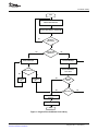
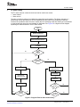
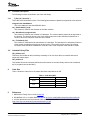
can be changed or modified using callback functions defined at the application level. Figure 1 is a
high-level flow diagram explaining the state transitions in an I2C routine.
2
Using the USI I2C Code Library
SLAA368 – September 2007
Submit Documentation Feedback
www.ti.com
I2C Master Library
Start
Initialize State Machine
Transmit Slave Address and R/W Bit
No
Did Slave
Acknowlege?
Yes
Yes
No
Perform Read
Operation?
Recieve One Byte
Transmit One Byte
Byte CTR = 0?
Receive ACK/NACK
From Slave
No
Send ACK
Bit
Yes
No
Send NACK
Bit
Did Slave
ACK?
Yes
Yes
Byte CTR = 0?
No
Invoke Callback
Function
Prepare for Stop
Stop
Figure 1. Program Flow for Master Code Library
SLAA368 – September 2007
Submit Documentation Feedback
Using the USI I2C Code Library
3
www.ti.com
2
I C Master Library
2.1
Usage From C
<br/>
Void main(void)
{
WDTCTL = WDTPW+WDTHOLD;
BCSCTL1 = CALBC1_1MHZ;
DCOCTL = CALDCO_1MHZ;
P1DIR |= 0x01;
P1OUT = 0x00;
// Stop watchdog
// Load DCO constants
// P1.0 as output (LED)
/* Initialize USI module, clock ~ SMCLK/128 */
TI_USI_I2C_MasterInit(USIDIV_7+USISSEL_2+USICKPL, StatusCallback);
/* Acknowledge polling function - LED blinks continuously until slave device
provides an ACK
TI_USI_I2CSelect(unsigned char SlaveAddress) */
while(TI_USI_I2CSelect(0x50))
{
P1OUT ^= 0x01;
// Toggle LED
for (i = 0; i < 0x3000; i++);
// Delay
}
P1OUT =0;
// Slave acknowledged, LED off
/* Transmit data to the EEPROM device, prefixed by page address 0x01
TI_USI_I2CWrite(SlaveAddress, Length, Multi, TxData) */
__disable_interrupt();
TI_USI_I2CWrite(0x50,9,0,TxData0);
__bis_SR_register(LPM0_bits + GIE);
/* Acknowledge polling function - loops continuously until slave device
provides an ACK */
while(TI_USI_I2CSelect(0x50));
/* Transmit data to the EEPROM device, prefixed by page address 0x08
TI_USI_I2CWrite(SlaveAddress, Length, Multi, TxData)*/
__disable_interrupt();
TI_USI_I2CWrite(0x50, 3, 0, TxData1);
__bis_SR_register(LPM0_bits + GIE); //*/
/* Acknowledge polling function - loops continuously until slave device
provides an ACK */
while(TI_USI_I2CSelect(0x50));
/* Reset address counter of the EEPROM device by transmitting the page
address to be read from (0x00) (Dummy write)
TI_USI_I2CWrite(SlaveAddress, Length, Multi, TxData)*/
__disable_interrupt();
TI_USI_I2CWrite(0x50,1, 1,TxData0);
__bis_SR_register(LPM0_bits + GIE);
/* Read data from the EEPROM device, starting at page address 0x00
TI_USI_I2CRead(SlaveAddress, Length, Multi, RxData)*/
4
Using the USI I2C Code Library
SLAA368 – September 2007
Submit Documentation Feedback
www.ti.com
I2C Master Library
__disable_interrupt();
TI_USI_I2CRead(0x50, 10, 1,RxData);
__bis_SR_register(LPM0_bits + GIE);
/* This function can be used to end any open I2C transaction.
Use only if I2C transaction was left open previously by setting stop
condition bit =1 */
TI_USI_I2CStop();
// check data for validity
for (j = 0;j<10;j++)
{
if (RxData[j]!=j)
{
while(1);
}
}
P1OUT |= 0x01;
while(1);
// data invalid, stay in loop
// data valid, LED on
// program ends here
}
int StatusCallback(unsigned char c)
{
return TI_USI_EXIT_LPM;
}
// Exit active for next transfer
The file USI_I2CMaster.h must be included to initialize variables and functions when using the library from
a C program. The TI_USI_I2C_MasterInit(…) function needs to be called only once at the start to initialize
the USI module in master mode.
In the previous example (example_EEPROM.c), the MSP430 master transmits a stream of data to the
AT 24C02, a two-wire serial EEPROM device. The device requires an 8-bit data word address following
the device address before data bytes can be written to it. The internal word address counter of the
EEPROM maintains the last address accessed during the previous data transmission. Hence, before a
read, the internal counter needs to be reinitialized by transmitting to the required data word address. At
the end of every write operation, the EEPROM enters an internally timed write cycle and does not respond
until the write operation is complete. At this time, it can be polled by the master device for an acknowledge
(ACK) using the TI_USI_I2CSelect function. This function returns a nonzero value if the slave sends a No
Acknowledge (NACK). Once the slave has acknowledged, the data is ready to be read from the EEPROM.
The transmitted and received data are compared and, if found to be valid, the LED is turned on. The data
can also be viewed in the memory through a watch window. The callback function is used to modify the
low-power mode for the next operation. The result of the previous operation is passed as an argument to
the callback function. A zero indicates that the previous operation was successful. An additional example
application to communicate with a dedicated slave MSP430 device is provided in the file
example_master430interface.c.
Note:
If C callback functions are used, the library needs to preserve additional CPU registers (C
scratch registers) across the callback function call, as these registers could be affected by
the callback function. If it can be ensured that the callback function does not modify the C
scratch registers, they need not be preserved. Preserving the C scratch registers
consumes additional code space and execution cycles. Therefore, the end user is given
the option of using a predefined macro within the library to preserve the C scratch
registers (USE_C_CONTEXT_SAVE is included) or leaving the registers as is
(USE_C_CONTEXT_SAVE is commented out). See the compiler documentation for more
details regarding C calling conventions.[2]
SLAA368 – September 2007
Submit Documentation Feedback
Using the USI I2C Code Library
5
www.ti.com
2
I C Master Library
2.2
Usage From Assembly
<br/>
RESET
StopWDT
SetupDCO
SetupPx
InitCall
mov.w
mov.w
mov.b
mov.b
bis.b
bic.b
mov.b
mov.w
call
#SFE(CSTACK),SP
#WDTPW+WDTHOLD,&WDTCTL
&CALBC1_1MHZ,&BCSCTL1
&CALDCO_1MHZ,&DCOCTL
#0x01,&P1DIR
#0x01,&P1OUT
#0xEA,R12
#StatusCallback,R14
#TI_USI_I2C_MasterInit
; Initialize stackpointer
; Stop WDT
; Load DCO calibration constants
#0x01,&P1OUT
#0xFFFF,R5
R5
L1
#AcknowledgePoll
#0,R12
SlaveDetect
&P1OUT
; Detect if slave is present...
; ... LED toggles until slave ACKS
;
;
;
;
Slave device present?
Is result zero (ACK)?
Loop until device acknowledges
Slave acknowledged, LED off
#0x50,R12
#9,R14
#Transmit1
#0x00
#TI_USI_I2CWrite
#4,SP
#LPM0+GIE,SR
#AcknowledgePoll
#0,R12
Poll_1
;
;
;
;
;
;
;
;
;
;
Slave address
length = 9
pointer to data buffer
generate stop
transmit data stream #1
compensate SP on return
enter LPM, enable interrupts
Device ready for next transfer?
Is result zero (ACK)?
Loop until device acknowledges
#0x50,R12
#3,R14
#Transmit2
#0x00
#TI_USI_I2CWrite
#4,SP
#LPM0+GIE,SR
#AcknowledgePoll
#0,R12
Poll_2
;
;
;
;
;
;
;
;
;
;
Slave address
length = 3
pointer to data buffer
generate stop
transmit data stream #2
compensate SP on return
enter LPM, enable interrupts
Device ready for next transfer?
Is result zero (ACK)?
Loop until device acknowledges
#0x50,R12
#1,R14
#Transmit1
#0x01
#TI_USI_I2CWrite
#4,SP
#LPM0+GIE,SR
;
;
;
;
;
;
;
Slave address
length = 1
pointer to data buffer
generate stop
transmit to reset internal counter
compensate SP on return
enter LPM, enable interrupts
#0x50,R12
#10,R14
#Receive
#0x01
#TI_USI_I2CRead
#4,SP
#LPM0+GIE,SR
;
;
;
;
;
;
;
Slave address
length = 10
pointer to data buffer
do not generate stop
receive stream#1,#2
compensate SP on return
enter LPM, enable interrupts
; P1.0& 1.1 as output
; USIDIV_7+USISSEL_2+USICKPL
; Callback fn. pointer
; Initialize USI master
SlaveDetect
xor.b
mov.w
L1
dec.w
jnz
Poll_0
call
cmp.b
jnz
clr.b
TransmitCall_1
mov.w
mov.w
push.w
push.w
call
add.w
bis.w
Poll_1
call
cmp.b
jnz
TransmitCall_2
mov.w
mov.w
push.w
push.w
call
add.w
bis.w
Poll_2
call
cmp.b
jnz
TransmitCall_3
mov.w
mov.w
push.w
push.w
call
add.w
bis.w
ReceiveCall
mov.w
mov.w
push.w
push.w
call
add.w
bis.w
6
Using the USI I2C Code Library
SLAA368 – September 2007
Submit Documentation Feedback
www.ti.com
I2C Master Library
StopTransaction
call
CheckResult
mov.w
clr.b
Compare
cmp.b
jz
clr.b
jmp
Increment
inc.b
inc.w
cmp.b
jnz
bis.b
EndProgram jmp
AcknowledgePoll
mov.b
call
ret
StatusCallback
mov.w
ret
#TI_USI_I2CStop
; Stop I2C transactions
#Receive,R6
R4
R4,0(R6)
Increment
&P1OUT
EndProgram
; store received data location
; data valid, continue
; data invalid, LED off
R4
R6
#10,R4
Compare
#0x01,&P1OUT
$
; if all 10 bytes are correct.
; ... turn on LED
; program ends here
#0x50,R12
#TI_USI_I2CSelect
; slave address
; Ack polling function
#1,R12
; wake up on exit
In assembly, the usage of the library is the same as in C. Arguments are passed using the C calling
convention (making the library functions compatible to both C and assembly usage). The first two
parameters are passed using registers R12 and R14; all others are pushed onto the stack.[2]
2.3
Function Description
The following functions are defined in the master code library.
2.3.1
TI_USI_I2C_MasterInit(…)
The function initializes the USI module for I2C communication. The parameters passed as arguments are:
unsigned char ClockConfig
This value contains the clock select, frequency divider, and clock polarity bits that are to be loaded
onto the control register USICTL0.
int (* StatusCallback) (unsigned char)
This function is called on the transmission/reception of the last byte in the communication stream. The
result of the previous operation (ACK/NACK) is passed as an argument to this function. The function
returns a zero if the existing low-power mode should be maintained or a nonzero value if the low-power
mode should be exited.
2.3.2
TI_USI_I2CSelect(…)
This function detects the presence of a slave by addressing it and determining if the slave responds with
an ACK/NACK. The following parameter is passed as an argument:
unsigned char SlaveAddress
This is the device address of the slave.
The return value is the result of the operation. The function returns a zero if the slave is present and has
acknowledged, and it returns a nonzero value if the slave is absent or not ready to acknowledge. For
example, this function can be used to poll slower slave devices like EEPROM while waiting for it to
complete an internally timed write cycle.
SLAA368 – September 2007
Submit Documentation Feedback
Using the USI I2C Code Library
7
www.ti.com
2
I C Master Library
2.3.3
TI_USI_I2CRead(…)
This function implements block-read master receiver functionality. The parameters passed as arguments
are:
unsigned char SlaveAddress
This is the device address of the slave.
unsigned int Length
This value is the number of bytes to be received.
unsigned char Multi
This variable is used to suppress the generation of I2C stop condition if the user wants to leave the
channel open for further transactions.
void *RxData
This pointer variable points to the memory location where the received data should be stored.
The function returns a zero if the operation was successful and a nonzero value if a NACK was received
at any time during the I2C transaction. It is valid only when no callback function is provided. Otherwise, the
function returns immediately, and the I2C transaction takes place in the background.
2.3.4
TI_USI_I2CWrite(…)
This function implements block-write master transmitter functionality. The parameters passed as
arguments are:
unsigned char SlaveAddress
This is the device address of the slave.
unsigned int Length
This value is the number of bytes to be transmitted.
unsigned char Multi
This variable is used to suppress the generation of I2C stop condition in case the user wants to leave
the channel open for further transactions.
void *TxData
This pointer variable points to the memory location of the data to be transmitted.
The function returns a zero if the operation was successful and a nonzero value if a NACK was received
at any time during the I2C transaction. It is valid only when no callback function is provided. Otherwise, the
function returns immediately, and the I2C transaction takes place in the background.
2.3.5
TI_USI_I2CStop( )
This function generates the I2C stop condition and can be used to end an open I2C transaction. It is
typically not used, as both transmit and receive functions generate a stop condition by default. It can be
used in conjunction with a read or write function when the Multi parameter has a nonzero value.
2.4
Included Library Files
USI_I2CMaster.s43
This library file includes all the functionality necessary to transmit and receive single and multiple bytes as
an I2C master device. It also contains the acknowledge polling function, which polls for the presence of a
slave device.
USI_I2CMaster.h
This header file has the necessary definitions and functions for the master library and must be included in
any C program that uses the library.
8
Using the USI I2C Code Library
SLAA368 – September 2007
Submit Documentation Feedback
www.ti.com
I2C Slave Library
3
I2C Slave Library
The I2C slave does not control the clock and can be used in two modes:
• Slave transmit
• Slave receive
The slave code library allows for multiple byte transmission and reception. The library executes in a
nonblocking manner and allows for the I2C transactions to take place in the background. Callback
functions are provided to allow the user to modify the CPU operating mode after each byte is transmitted
or received and also store the received data for application use. Figure 2 is a high-level flow diagram
explaining the state transitions in an I2C slave routine.
Start
Initialize State Machine
Invoke Start Callback Function
Receive Slave Address
and R/W Bit
Device
Address
Correct?
No
Yes
Yes
Perform Read
Operation?
No
Invoke Transmit
Callback Function
Receive Byte
Transmit Byte
Invoke Receive
Callback Function
Receive
ACK/NACK
Send ACK
NACK
Received
Yes
No
Yes
Restart
Condition
Received?
No
No
Restart
Condition
Received?
Yes
Figure 2. Program Flow for Slave Code Library
SLAA368 – September 2007
Submit Documentation Feedback
Using the USI I2C Code Library
9
www.ti.com
2
I C Slave Library
3.1
Usage From C
<br/>
void main(void)
{
WDTCTL = WDTPW + WDTHOLD;
BCSCTL1 = CALBC1_1MHZ;
DCOCTL = CALDCO_1MHZ;
P1DIR |= 0x01;
P1OUT = 0;
FCTL1 = FWKEY + ERASE;
FCTL2 = FWKEY + FSSEL_2 + FN0;
FCTL3 = FWKEY;
*(unsigned int *)0x1000 = 0;
FCTL1 = FWKEY;
FCTL3 = FWKEY+LOCK;
// Stop watchdog
// Set DCO
// Enable P1.0 as output
//
//
//
//
Enable flash erase
Flash timing setup
Disable lock
Dummy write to erase flash
// Diasble flash write
/* Initialize USI module in Slave mode */
TI_USI_I2C_SlaveInit(OwnAddress,StartCallback,RxCallback,TxCallback);
while(1)
{
__disable_interrupt();
__bis_SR_register(LPM4_bits + GIE);
// enter LPM, enable interrupts
__no_operation();
}
}
void StartCallback()
{
P1OUT |= 0x01;
}
int RxCallback(unsigned char RxData)
{
// Received data byte is stored in flash
FCTL3 = FWKEY;
FCTL1 = FWKEY+ WRT;
*(unsigned char*)ptr_rx = RxData;
ptr_rx++;
FCTL1 = FWKEY;
FCTL3 = FWKEY + LOCK;
return TI_USI_STAY_LPM ;
}
// start received, turn LED on
// Enable flash write
// Write data to flash
// Increment Rx pointer
// Disable flash write
// stay in LPM
int TxCallback(int* TxDataPtr)
{
// Data byte to be transmitted is passed through reference to the library
*(unsigned char*)TxDataPtr = *(unsigned char*)ptr_tx;
ptr_tx++;
// Increment tx pointer
return TI_USI_STAY_LPM ;
// stay in LPM
}
10
Using the USI I2C Code Library
SLAA368 – September 2007
Submit Documentation Feedback
www.ti.com
I2C Slave Library
The file USI_I2CSlave.h must be included to initialize variables and functions when using the library from
a C program. The TI_USI_I2C_SlaveInit(…) function needs to be called only once at the start to initialize
the USI module in slave mode. The slave program (example_slave430interface.c) runs on the dedicated
slave MSP430, while the master program (example_master430interface.c) runs in parallel on the
dedicated master MSP430 device. The slave device uses the Info D segment (0x1000 to 0x104F) to
emulate an EEPROM with 64-byte data storage. On reception of the start condition from the master, the
StartCallback() function is called. This function can be used to refresh data pointers before a transmit or a
receive operation.
In the previous example, the StartCallback() function turns on the LED to indicate that the I2C transaction
has started. The master MSP430 transmits 16 bytes of data and then reads it back from the slave
MSP430. On the reception of each data byte, the RxCallback() function is called. The received data byte
is passed as an argument to this function, and the return value is used to modify the low-power mode. The
TxCallback() function is called before each transmit operation. The function passes the data byte to be
transmitted indirectly using a reference pointer. It also returns a zero if the existing low-power mode
should be maintained or a nonzero value if the low-power mode should be exited. The data can be
validated by viewing the Info D segment of flash.
Note:
If C callback functions are used, the library needs to preserve additional CPU registers (C
scratch registers) across the callback function call, as these registers could be affected by
the callback function. If it can be ensured that the callback function does not modify the C
scratch registers, they need not be preserved. Preserving the C scratch registers
consumes additional code space and execution cycles. Therefore, the end user is given
the option of using a predefined macro within the library to preserve the C scratch
registers (USE_C_CONTEXT_SAVE is included) or leaving the registers as is
(USE_C_CONTEXT_SAVE is commented out). See the compiler documentation for more
details regarding C calling conventions.[2]
SLAA368 – September 2007
Submit Documentation Feedback
Using the USI I2C Code Library
11
www.ti.com
2
I C Slave Library
3.2
Usage From Assembly
<br/>
RESET
StopWDT
SetupDCO
SetupPx
EraseFlash
mov.w
mov.w
mov.b
mov.b
bis.b
mov.w
mov.w
mov.w
mov.w
mov.w
mov.w
mov.w
mov.w
#SFE(CSTACK),SP
;
#WDTPW+WDTHOLD,&WDTCTL ;
&CALBC1_1MHZ,&BCSCTL1
;
&CALDCO_1MHZ,&DCOCTL
#0x03,&P1DIR
;
#FWKEY+ERASE,&FCTL1
;
#FWKEY+FSSEL_2+FN0,&FCTL2
#FWKEY,&FCTL3
;
#0,&0x1000
;
#FWKEY,&FCTL1
#FWKEY+LOCK,&FCTL3
#0x1000,&RxFlashPtr
;
#0x1000,&TxFlashPtr
;
Initialize stackpointer
Stop WDT
Load DCO calibration constants
#0x48,R12
#StartCallback,R14
#TxCallback
#RxCallback
#TI_USI_I2C_SlaveInit
#4,SP
#LPM4+GIE,SR
$
;
;
;
;
;
;
;
Address of slave
StartCallback fn. ptr
Tx Callback fn. ptr
Rx Callback fn. ptr
I2C Slave initialize
compensate stack pointer
enter LPM, enable interrupts
#0x01,&P1OUT
; start received, LED on
&TxFlashPtr,R6
@R6,0(R12)
&TxFlashPtr
#0,R12
;
;
;
;
pass data to be transmitted ...
... to the library
increment tx pointer
stay in LPM
#FWKEY+WRT,&FCTL1
#FWKEY,&FCTL3
&RxFlashPtr,R6
R12,0(R6)
#FWKEY,&FCTL1
#FWKEY+LOCK,&FCTL3
&RxFlashPtr
#0,R12
;
;
;
;
Set WRT bit
Clear lock bit
Move rxed byte to ...
... flash location
P1.0 and 1.1 as output
Set erase bit
; Set flash timing
Clear lock bit
Dummy write to start Flash erase
Initialize Rx pointer
Initialize Tx pointer
SlaveCall
mov.b
mov.w
push.w
push.w
call
add
bis.w
jmp
StartCallback
bis.b
ret
TxCallback
mov.w
mov.b
inc.w
mov.w
ret
RxCallback
mov.w
mov.w
mov.w
mov.b
mov.w
mov.w
inc.w
mov.w
ret
; lock flash
; stay in LPM
In assembly, the usage of the library is the same as in C. Arguments are passed using the C calling
convention (making the library functions compatible for both C and assembly usage). The first two
parameters are passed using registers R12 and R14; all others are pushed onto the stack.[2]
12
Using the USI I2C Code Library
SLAA368 – September 2007
Submit Documentation Feedback
www.ti.com
Code Size
3.3
Function Description
The following functions are defined in the slave code library:
3.3.1
TI_USI_I2C_SlaveInit(...)
This is the slave initialization function. The following parameters are passed as arguments to this function:
unsigned char OwnAddress
This is the address of the slave MSP430 device.
int (* StartCallback) (void)
This function is called on the detection of the start condition.
int (* RxCallback) (unsigned char)
This function is called on the reception of a data byte. The received data is passed as an argument to
the function. The function returns a zero if the existing low-power mode should be maintained or a
nonzero value if the low-power mode should be exited.
int (* TxCallback) (int*)
This function is called before the transmission of a data byte. The data byte to be transmitted is stored
at the location provided as an argument to this function. The function returns a zero if the existing
low-power mode should be maintained or a nonzero value if the low-power mode should be exited.
3.4
Included Library Files
USI_I2CSlave.s43
This library file includes all the functionality necessary for an I2C slave device to transmit and receive
single and multiple bytes.
USI_I2CSlave.h
This header file has the necessary definitions and functions for the slave library and must be included in
any C program that uses the library.
4
Code Size
Table 1 shows the code size for the master and slave code libraries in IAR.
Table 1. Code Size (IAR)
CODE LIBRARY
USE_C_CONTEXT_SAVE
SIZE (bytes)
0
616
1
628
0
408
1
444
Master
Slave
5
References
1. MSP430x2xx Family User’s Guide (SLAU144)
2. IAR MSP430 C/C++ Compiler Reference Guide (ftp://ftp.iar.se/WWWfiles/msp430/guides/oc430.pdf)
3. I2C-Bus Specification and User Manual, NXP Semiconductors, 2007
(http://www.nxp.com/acrobat/usermanuals/UM10204_3.pdf)
SLAA368 – September 2007
Submit Documentation Feedback
Using the USI I2C Code Library
13
IMPORTANT NOTICE
Texas Instruments Incorporated and its subsidiaries (TI) reserve the right to make corrections, modifications, enhancements, improvements,
and other changes to its products and services at any time and to discontinue any product or service without notice. Customers should
obtain the latest relevant information before placing orders and should verify that such information is current and complete. All products are
sold subject to TI’s terms and conditions of sale supplied at the time of order acknowledgment.
TI warrants performance of its hardware products to the specifications applicable at the time of sale in accordance with TI’s standard
warranty. Testing and other quality control techniques are used to the extent TI deems necessary to support this warranty. Except where
mandated by government requirements, testing of all parameters of each product is not necessarily performed.
TI assumes no liability for applications assistance or customer product design. Customers are responsible for their products and
applications using TI components. To minimize the risks associated with customer products and applications, customers should provide
adequate design and operating safeguards.
TI does not warrant or represent that any license, either express or implied, is granted under any TI patent right, copyright, mask work right,
or other TI intellectual property right relating to any combination, machine, or process in which TI products or services are used. Information
published by TI regarding third-party products or services does not constitute a license from TI to use such products or services or a
warranty or endorsement thereof. Use of such information may require a license from a third party under the patents or other intellectual
property of the third party, or a license from TI under the patents or other intellectual property of TI.
Reproduction of TI information in TI data books or data sheets is permissible only if reproduction is without alteration and is accompanied
by all associated warranties, conditions, limitations, and notices. Reproduction of this information with alteration is an unfair and deceptive
business practice. TI is not responsible or liable for such altered documentation. Information of third parties may be subject to additional
restrictions.
Resale of TI products or services with statements different from or beyond the parameters stated by TI for that product or service voids all
express and any implied warranties for the associated TI product or service and is an unfair and deceptive business practice. TI is not
responsible or liable for any such statements.
TI products are not authorized for use in safety-critical applications (such as life support) where a failure of the TI product would reasonably
be expected to cause severe personal injury or death, unless officers of the parties have executed an agreement specifically governing
such use. Buyers represent that they have all necessary expertise in the safety and regulatory ramifications of their applications, and
acknowledge and agree that they are solely responsible for all legal, regulatory and safety-related requirements concerning their products
and any use of TI products in such safety-critical applications, notwithstanding any applications-related information or support that may be
provided by TI. Further, Buyers must fully indemnify TI and its representatives against any damages arising out of the use of TI products in
such safety-critical applications.
TI products are neither designed nor intended for use in military/aerospace applications or environments unless the TI products are
specifically designated by TI as military-grade or "enhanced plastic." Only products designated by TI as military-grade meet military
specifications. Buyers acknowledge and agree that any such use of TI products which TI has not designated as military-grade is solely at
the Buyer's risk, and that they are solely responsible for compliance with all legal and regulatory requirements in connection with such use.
TI products are neither designed nor intended for use in automotive applications or environments unless the specific TI products are
designated by TI as compliant with ISO/TS 16949 requirements. Buyers acknowledge and agree that, if they use any non-designated
products in automotive applications, TI will not be responsible for any failure to meet such requirements.
Following are URLs where you can obtain information on other Texas Instruments products and application solutions:
Products
Amplifiers
Data Converters
DSP
Clocks and Timers
Interface
Logic
Power Mgmt
Microcontrollers
RFID
RF/IF and ZigBee® Solutions
amplifier.ti.com
dataconverter.ti.com
dsp.ti.com
www.ti.com/clocks
interface.ti.com
logic.ti.com
power.ti.com
microcontroller.ti.com
www.ti-rfid.com
www.ti.com/lprf
Applications
Audio
Automotive
Broadband
Digital Control
Medical
Military
Optical Networking
Security
Telephony
Video & Imaging
Wireless
www.ti.com/audio
www.ti.com/automotive
www.ti.com/broadband
www.ti.com/digitalcontrol
www.ti.com/medical
www.ti.com/military
www.ti.com/opticalnetwork
www.ti.com/security
www.ti.com/telephony
www.ti.com/video
www.ti.com/wireless
Mailing Address: Texas Instruments, Post Office Box 655303, Dallas, Texas 75265
Copyright © 2008, Texas Instruments Incorporated