1
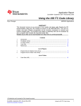
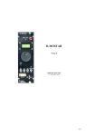
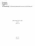
QUICK START GUIDE
MODEL DXA/DXI 100/200
DIGITAL ACCELEROMETER &
INCLINOMETER
JEWELL INSTRUMENTS, LLC
850 Perimeter Road
Manchester, NH 03103
PHONE: (800) 227-5955
E-MAIL: [email protected]
Jewell Instruments DXA/DXI Quick Start Guide v. 7/2013
DXA-DXI Quick Start Guide
A)
Hardware Connections
The DXA/I Unit make use of a barrel style connector (MS27476Y10D35P)
for interface with the external systems. In order to communicate with your
DXA/I Unit please connect the following:
B)
Functional Connections
Pin Number
[+] POWER
12
[-] RETURN
11
D+ / TX+
4
D- / TX-
5
Case Ground (Optional)
3
Packet Structure & Decoding
Packet Structure:
Each data packet received from the unit consists of 7 bytes when either polled
(RS-485) or set to continuous sending mode (Emulated RS-422). The
quantitative data output is 18 bits long in the D0, D1, D2 bytes. The order and
significance of these bytes is fixed and is explained the following:
7 Byte Data Packet:
[Prefix][UAID][D0][D1][D2][Aux][Checksum]
[Prefix]: The prefix byte will always start the beginning of any data packet.
The value of this prefix for all data packets will be 0xA6.
[UAID]: The UAID byte serves as both the identifier for which axis is
transmitting on a particular unit and the address for incoming commands to a
unit. The UAID consists of 2 parts a 6 bit [BASE] concatenated with a 2 bit
[OFFSET]. Only the base is user selectable. The default address for a unit is
X Axis: [0x71] and Y Axis: [0x72]. The default base value is [0x1C]
standalone or [0x70] when left justified in the UAID Byte.
[D0]: This is the first byte which contains output data; it is also referred to as
the status byte. It contains the two least significant bits and the remainder (6
Jewell Instruments DXA/DXI Quick Start Guide v. 7/2013
bits) represents the flag and code portions of the status byte. The following is
the binary breakout of the status byte:
0b[XX]
[XXX] [XXX]
LSBs Data FLAG CODE
[D1]: This byte consists entirely of data output and it is MSB in relation to
the 2 bits in [D0] but is placed in midpoint in the full 18 bit data output.
[D2]: This byte consists entirely of data output and it is MSB in relation to
both [D1] and [D0:7,8] as seen below.
D2:[ _ _ _ _ _ _ _ _ ] D1:[ _ _ _ _ _ _ _ _ ] D0:[ _ _ | _ _ _ |_ _ _ ]
[Aux]: The Auxiliary byte serves a variety of purposes that are dependent on
the configuration parameters. Functions include indicating the current
DCOCTL register value, number of samples in an output average, etc.
[Checksum]: Checksum computation for packet transmission verification.
Decoding:
DXA Models: Value is in fractional g’s, with 17 fraction bits. These results in
the MSB representing the largest fractional portions of the output value where bit
16 of 0:17 represent 0.5g.
Available integer sizes in C are generally (8<<n) bits. If 16 bits are enough, you
can store just D2 and D1 as a Q15 (i.e., 15 fraction bits) value. To include the 2
LSb’s, you would have to use a 32-bit integer. If you store it left-justified in the
32-bit integer and mask off the Flag bits, scale will be Q31. 0x00000000 is midvalue (0g, or 0 degrees). 0x7fffc000 and 0x80000000 represent +/- 1g, minus 1
resolution unit at the positive end. Reading will “peg” at these values, but the
instrument is specified only over its calibrated range - these end values may not
even be reachable.
Jewell Instruments DXA/DXI Quick Start Guide v. 7/2013
The data can be read as a 32 bit signed integer, type int or long depending on your
architecture. Store the bytes D0, D1, D2 into Reading with D2 occupying the
MSB of the data element.
Reading &= 0xffffc000;
// Mask off the Flag and Code bits
//Acceleration is type float or double.
Acceleration /* g’s */ = (float) Reading/0x80000000ul;
DXI Models: Value is in milli-degrees, 1 sign bit and 17 incremental bits. These
results in the MSB representing the largest value as a standard unsigned integer of
the output value where bit 0 of 0:17 represent 0.001 Degrees.
Available integer sizes in C are generally (8<<n) bits. If 16 bits are enough, you
can store just D2 and D1 as a Q15 (i.e., 15 bits with a minimum resolution of
0.004 degrees) value. To include the 2 LSB’s you would have to use a 32-bit
integer. If you store it left-justified in the 32-bit integer and mask off the Flag
bits, scale will be Q31. Reading will “peg” at these values, but the instrument is
specified only over its calibrated range - these end values may not even be
reachable.
The calibrated Full Scale + and – inclination values for a unit with +/- 60 degree
“full-scale reading” correspond to +/- 60 deg. In the Q31 scaled integer above
with 18 actual data bits, +60 degrees corresponds to 0x3A980000, and -60
degrees corresponds to (-0x3A980000) / [0x3A980000+Ox80000000] /
0xBA980000. Converting these back to angle yields +/- 60.000 degrees.
Reading the data as a 32 bit fixed signed integer, type int or long depending on
your architecture. Store the bytes D0, D1, D2 into Reading with D2 occupying the
MSB of the data element.
Reading &= 0xffffc000;
// Mask off the Flag bits
if(Reading & 0x80000000) // Determine if signed
{ Set_Negative = TRUE;
Reading -= 0x80000000;}
Reading = Reading >> 14;
// Shift for scaling in 32b
if(Set_Negative)
{(float)Reading *= -1000;} // Reading represented as -xx.xxx degrees.
else
{(float) Reading *= +1000;} // Reading represented as +xx.xxx degrees.
Jewell Instruments DXA/DXI Quick Start Guide v. 7/2013
C)
Command Structuring
Commands sent to the unit are set by a specific firmware structure which
includes a static prefix, unit addressing, the arguments, and a verification
checksum. In this subsection we will cover the different elements of the
command structure and identify each element’s purpose and manipulation.
[PREFIX]: In order to determine the length of a command being received by
the DXA / DXI unit the value of a command prefix is predetermined as seen
in the following table:
COMMAND TYPE PREFIX COMMAND LENGTH
Short
0xA9
3 Bytes
Long
0xAC
4 Bytes
Extended
0xAF
5 Bytes
[ADDRESS]: This value will correspond with the UAID of the desired unit
being targeted for command.
[ARGUMENT]: The argument for a command can be either 0-2 bytes. The
only command for which an argument isn’t required is the poll command
where a combination of the prefix and unit address satisfies the requirements
for decoding. For single action commands as in turning off RS-422 emulation
off, or turning on averaging, one argument is used. In the event a command is
issued where the tuning of a specific parameter is required, the argument
consists of one static byte to identify the primary command and the user
selected value as an unsigned integer.
[CHECKSUM]: In order to calculate the checksum for any command
complete the Hexadecimal addition of all non checksum bytes. Take the least
significant nibble overflow from the addition and add it back into the sum.
The next step is to NOT the sum. Ex:
Command: AC 72 B1 [Checksum]
AC
+
72
=
11E
11E
+
B1
=
1CF
[01][CF] First Nibble = 1
01 +
CF
=
D0
~DO = 2F = Checksum
Just as a note when using the BREAK command it is recommended that the
command be spaced by 2 ‘Rubout’ characters (0xFF) especially at higher
baud rates. In order to see a full list of commands please refer to your
DXA/DXI User Manual.
Jewell Instruments DXA/DXI Quick Start Guide v. 7/2013
D)
Default Address Partial Fixed Command Listing
In order to quickly begin integrating your DXA/DXI unit in your application
the following section will outline commonly used commands with fixed
(default) addresses and pre-calculated checksums. Acknowledges are
provided for the commands that execute them. A command which address
both axes simultaneously will respond with acknowledges independently from
each axis.
Command
Poll Both Axis
Poll X
Poll Y
Set Baud 19.2k X&Y
Set Baud 38.4k X&Y
Turn ON RS-422 Emulation X&Y
Turn OFF RS-422 Emulation X&Y
Allow Update X&Y
Update Configuration X&Y
Averaging ON X&Y
RESET X&Y
E)
Hexadecimal
Sequence
A9 73 E2
A9 71 E4
A9 72 E3
AC 73 B0 2F
AC 73 B1 2E
AC 73 C3 1C
AC 73 C2 1D
AC 73 01 DE
AC 73 00 DF
AC 73 C5 1A
AC 73 03 DC
Acknowledge /
~Acknowledge
(2) 7 Byte Data Packets
7 Byte Data Packet
7 Byte Data Packet
A3 71 B0 3A A3 72 B0 39
A3 71 B1 39 A3 72 B1 38
A3 71 C3 27 A3 72 C3 26
A3 71 C2 28 A3 72 C2 27
A3 71 01 E9 A3 72 01 E8
A3 71 00 EA A3 72 00 E9
A3 71 C5 25 A3 72 C5 24
No Acknowledge
Using your DXA/DXI Demo Program
Included with your DXA / DXI Digital Inclinometer was a Demonstration
Software installation. After uncompressing the folder from the media
provided, install the Labview virtual instrument (VI).
Jewell Instruments DXA/DXI Quick Start Guide v. 7/2013
Upon program launch you are presented with the operational mode selection
for your unit. Please select your operating mode, baud rate, the COM port of
your RS 485/422 reader and if you are interfacing with a DXA or DXI Unit.
The factory default values are RS-422 & 38400 Baud.
Due to the nature of emulated RS-422 operation on the DX unit the subprogram within the DXA /DXI demo is primarily a reader. However since the
break command is only applied to a unit set to RS-422 mode it is included in
this sub-section. In order to allow for the input of any commands, the unit
must accept a break command in order to stop transmission before the unit
starts streaming data. This must occur in a 28 mS window at power on. In
order to facilitate this process the RS-422 sub-mode of the DXA/DXI Demo
has the break command built in for easy transition to the temporary RS-485
unit state.
Pressing the break button near the bottom of the VI window will automate
sending the Break command continuously with rubouts. As the user you need
to cycle power during this 5 second window. After the time has elapsed the
VI will default back into the RS-485 mode as the unit should now be in a
temporary RS-485 mode.
If you have previously set the unit into a RS485 state please click the toggle
switch at the home page in order to enter the RS-485 mode after selecting
your other DXA / DXI parameters. The RS-485 portion of the demo program
still decodes the outputs for you but when the unit is polled but also has
several pre-constructed command inputs for the change of primary
characteristics. The majority of these are changing ON/OFF characteristics
with 2 exceptions. For more detailed explanations of the pre-constructed
command input functions please refer to the DXA / DXI Manual.
Jewell Instruments DXA/DXI Quick Start Guide v. 7/2013
Of the two commands which take inputs within the DXA / DXI Demo
program, the poll continuous command polls does not take the input field as
an argument to send to the unit. Instead the poll continuous function uses the
input field to control the rate at which the poll command is sent to both axis.
The Set-Max Avg. Time input value of the function under the same name
allows for an unsigned integer value between 1 and 255 to be entered. This
entry is used in order to convert that number back into the unsigned
hexadecimal equivalent. At which point it is used as the second argument for
the function and the checksum is calculated for the user. For more
information on the implementation and calculating the effective 1 pole filter
target value see the DXA / DXI Manual.
F)
Operational Modes and Mode Conversion
The DXA / DXI have 2 dedicated operational modes and one intermediary
operational mode. This can be seen below in the operational mode flowchart:
Jewell Instruments DXA/DXI Quick Start Guide v. 7/2013
RS-422
Operation
RS-485
Operation
Yes
No
Temporary
RS-485
Operation
Is RS-422
Emulation
Turned On?
28 mS
Start-Up
Window
While in startup Window
Yes
Was the BREAK
Command
Received?
Start Up
No
RESET
The RS-422 operational mode has been designed to continuously send a
stream of data outgoing without interruption for parameter adjustment. Once
in this operational mode the Rx Ports on the DSP are disabled even when
commands can be fit between output packets.
The RS-485 operational mode has been designed to provide data when polled
and allow for the use of the dual purpose Tx / Rx data connections to receive
data into the unit. This incoming data can provide adjustment to averaging,
polarity, operational mode, effective filtering etc…
The third operational mode is a temporary RS-485 mode which behaves in the
exact some fashion and the standard RS-485 mode with one exception. While
in the temporary RS-485 mode, a power cycle or RESET command will cause
the system to reboot. At which point if enabled default back into RS-422
Emulation. Namely the RS-485 mode if designed for 2 primary purposes to
allow for the permanent transition between RS-422 and RS-485 modes by
sending the turning off the RS-422 Emulation sub variable. Or in this case to
set the operational conditions under which RS-422 operation will permanently
resume.
The primary method for transitioning between modes is based in 3 commands:
BREAK, 422 Emulation ON, and 422 Emulation OFF. As shown before if
the unit is currently set with 422 Emulation ON then the BREAK command
must be used in order before the unit starts sending. For convenience this
Jewell Instruments DXA/DXI Quick Start Guide v. 7/2013
functionality is built into the DXA / DXI Demo program. However in order to
do it manually the following procedure should be observed:
1: Using a terminal emulator program or otherwise controllable data line
monitor and control set-up; write a Hexadecimal command string that reads as
the following:
0x[AC][UAID][02][Checksum][FF][FF]
This command consists of the BREAK concatenated with 2 Rubout and
should be sent a sufficient amount of times constantly in order cover the 28
mS start up window. Take into account the time between break rubout
execution start time and power cycle if your power supply will need to be
disconnected manually we can call this system power delay. For a graphical
timeline representation please see below:
Start-Up Window
Power to System
System Power
Delay
BREAK / Rubout Loop Execution Time
Time
2: If successful, the unit will stop sending any data and appear idle. If true,
you have successfully placed the unit into temporary RS-485 mode. You can
confirm this by requesting a executing a poll command. If untrue, the unit
will continue to send data constantly and the process in step one will need to
be repeated. Once in temporary RS-485 mode, if the unit needs to be placed
into a permanent RS-485 mode, the Turn RS-422 Emulation OFF command
must be executed. If you are just modifying parameters to then return to RS
422 mode execute the applicable commands. In either situation the final
parameter altering command should be followed by allow update and update
configuration. If you placed the unit in permanent RS-485 mode upon power
cycle the unit should not be transmitting and is waiting for your polling.
3: In order to make the transition from RS-485 operation to RS-485 operation
the break command not required. Instead, RS-422 operations are reactivated
by sending the Turn 422 Emulation ON command followed by Allow Update
and Update configuration. Upon RESET or power cycle for this operation the
unit should begin transmitting once the start up window has elapsed. If it fails
to transmit the unit is still in RS-485 Mode.
Jewell Instruments DXA/DXI Quick Start Guide v. 7/2013