1
Application Report
SLAA386A – January 2008 – Revised February 2008
PMBus Implementation Using the MSP430 USCI
Priya Thanigai ..................................................................................................... MSP430 Applications
ABSTRACT
This document provides an example application for the Power Management Bus
(PMBus) protocol implementation using the MSP430 as a master PMBus device. The
PMBus protocol is an open-standard power-management protocol used for
communicating with power conversion devices. It is implemented using the popular I2C
communication protocol at a hardware level and is controlled by a software interface of
PMBus commands. The demonstration application has been created for use with the
MSP430 USCI module configured in I2C mode. The code is intended for single
master-slave applications only.
Contents
Introduction .......................................................................................... 2
PMBus Protocol ..................................................................................... 2
2.1
PMBus Layer ............................................................................... 3
2.2
PMBus Protocol Formats ................................................................. 4
3
PMBus and MSP430 ............................................................................... 5
3.1
Configuring MSP430 Modules ........................................................... 5
3.2
Software Implementation ................................................................. 6
4
Example Application: Using the UCD9112 Synchronous Buck Controller Slave .......... 7
5
Function Description ............................................................................... 9
5.1
USCI I2C Interface Functions ............................................................ 9
5.2
PMBus Interface Functions ............................................................. 10
6
Application Examples ............................................................................. 12
6.1
General PMBus Status Polling ......................................................... 12
6.2
Alert Line Implementation ............................................................... 13
6.3
Control Line Implementation ............................................................ 14
6.4
Packet Error Check Implementation ................................................... 15
7
Code Size .......................................................................................... 15
8
References ......................................................................................... 15
Appendix A
Associated Files ......................................................................... 16
1
2
List of Figures
1
2
3
4
5
6
7
Communication Model .............................................................................
Send Byte Protocol .................................................................................
Read Byte Protocol .................................................................................
Write Byte Protocol .................................................................................
Read Word Protocol ................................................................................
Software Architecture ..............................................................................
MSP430 PMBus Interface to UCD9112 .........................................................
1
2
Differences Between I C, SMBus, and PMBus Protocols ..................................... 2
Code Size (IAR) ................................................................................... 15
3
4
4
4
5
6
8
List of Tables
2
All trademarks are the property of their respective owners.
SLAA386A – January 2008 – Revised February 2008
Submit Documentation Feedback
PMBus Implementation Using the MSP430 USCI
1
www.ti.com
Introduction
1
Introduction
The Power Management Bus (PMBus) is an industry-wide standard that can be viewed as a step toward
unifying communication standards for power conversion and digital power-management devices. It was
developed by the PMBus Implementers Forum (PMBus-IF). The standard uses the widely accepted
Inter-Integrated Circuit (I2C) communication protocol for the hardware interface. A number of additional
features serve to enhance the basic I2C communication protocol. The PMBus standard is also considered
to be an extension to the System Management Bus (SMBus) protocol that was popularized by the SBS
Implementers Forum for battery systems.[1]
This application report serves as a guide to implementing the PMBus protocol on MSP430 host
microcontroller devices with the USCI module. An example application is used to demonstrate the master
MSP430 PMBus interface with a UCD9112 buck controller.
2
PMBus Protocol
The PMBus standard was developed by a group of companies that envisioned the need for a
power-management protocol that has a well-defined physical communication layer and includes support
for implementing commonly used power-management commands. I2C was considered the preferred
standard for implementing the physical communication layer because it provided a simple means to relay
data representing commands, control, and information over a serial bus.[3] In addition to the data and
clock lines provided by I2C, the PMBus protocol implements the optional alert response (for host
notification in the presence of a fault) and control line (for turning the slave device on/off). The PMBus
command layer provides a set of 256 commands that the host microcontroller can use to instruct slave
PMBus devices.
Note:
PMBus commands and their functionality as mentioned in this application report can be
found in PMBus Specification Part II, Appendix I.[3]
The PMBus protocol also implements a timeout feature (present in SMBus) that prevents slower slave
devices from holding the clock line for longer than the specified timeout interval. This limits the minimum
allowable frequency of I2C transactions to 10 kHz, similar to SMBus but absent in I2C. For further
differences in timing and DC specifications between the protocols, see System Management Bus (SMBus)
Specification V2.0.[1] A new feature that increases reliability and robustness of this protocol is Packet
Error Checking (PEC). PEC was first introduced in version 1.1 of the SMBus protocol and is implemented
by using a Cyclic Redundancy Check-8 (CRC-8) algorithm to validate the integrity of a transaction.
It should be noted that PMBus can function as a 2-wire protocol. The data and clock lines are retained
from the I2C protocol for transmitting/receiving data and for controlling the clocking of data respectively.
The alert response and control signals are optional implementations/enhancements for host
microcontrollers that are willing to trade two GPIO pins for the ability to service a system fault and to turn
the slave device on or off using software. Table 1 briefly lists the significant differences between these
protocols.
Table 1. Differences Between I2C, SMBus, and PMBus Protocols
Protocol
Alert Response
Control Line
Maximum Timeout
Minimum
Frequency
PEC
2
I C
No
No
No
0 (DC)
No
SMBus
Yes
No
35 ms
10 kHz
Yes
PMBus
Yes
Yes
35 ms
10 kHz
Yes
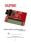
Figure 1 shows the architecture of the PMBus host microcontroller's communication model. The
application layer is at the user-interaction level and also can be viewed as a data translation/interpretation
layer. It performs application services and issues requests to the PMBus layer. The PMBus layer accepts
commands from the application layer. It processes these commands and instructs the hardware access
(I2C) layer on how to execute them. The I2C layer, in conjunction with the alert response and control line,
provides the physical interface needed for direct communication with the slave device.
2
PMBus Implementation Using the MSP430 USCI
SLAA386A – January 2008 – Revised February 2008
Submit Documentation Feedback
www.ti.com
PMBus Protocol
PMBus Master Device
Application Layer
PMBus Layer
Clock
Ports
PMBus Slave Device
2
I C Layer
Data
Control
Alert
Figure 1. Communication Model
2.1
PMBus Layer
The following significant features uniquely identify the PMBus protocol and establish its position as a
valuable part of any power-management system.
2.1.1
Alert Signal (SMBALERT)
The SMBALERT line is used by slave devices to notify the master in the presence of a system fault. This
line is a wired-AND signal and is tied high at reset similar to I2C clock and data lines. The slave device
can pull it low at any time to notify the host microcontroller that it needs to communicate. When the master
PMBus device receives an alert from the slave, the master can be configured to read the status registers
of the slave device to determine the type and location of the fault. Once the fault has been read and
recorded, the slave device can be notified and its status registers reinitialized.
In systems that have multiple slaves tied to the bus, the master uses the Alert Response Address (ARA)
to determine which slave pulled the alert line low. If multiple slaves are asserting the alert simultaneously,
the slave with the lowest address wins. This application report, however, deals with alert response
implementation for single slave only; for multi-slave implementation with the alert response, see System
Management Bus (SMBus) Specification V2.0.[1]
2.1.2
Control Signal (CONTROL)
On/off control of the slave device is achieved by using the control line in combination with commands on
the bus. The control line is configured as active high or active low based on the ON_OFF_CONFIG
command. The OPERATION command can then be used to turn the slave device on/off through software.
2.1.3
Packet Error Checking (PEC)
PEC is optionally implemented in PMBus devices but is highly recommended due to the critical nature of
data validity in power-management systems. Packet Error Code (also PEC) bytes are generated using the
popular CRC-8 algorithm that is based on performing XOR operations on the input bit stream with a fixed
CRC polynomial. The PEC byte is calculated on all bytes in the I2C transaction including device address
and read/write. PEC does not include start, stop, ACK/NACK, and repeated start bits.
SLAA386A – January 2008 – Revised February 2008
Submit Documentation Feedback
PMBus Implementation Using the MSP430 USCI
3
www.ti.com
PMBus Protocol
2.2
PMBus Protocol Formats
To understand implementation of PMBus commands and their classification, a brief overview of PMBus
protocol formats is needed. All PMBus commands defined in the standard can be classified under one of
the formats in the following sections.[1]
2.2.1
Send Byte
This format is typically used to instruct the slave device to perform a specified action. The I2C action for
this format is to transmit one byte. For example, the CLEAR_FAULTS command instructs the slave device
to clear all faults and reinitialize fault registers. This format also can be used to enable or disable a certain
feature in the slave device. A graphical representation of the Send Byte format is shown in Figure 2.
S = Start
1
7
1
1
8
1
1
S
Slave Address
W
A
Command Byte
A
P
P = Stop
Sr = Repeated Start
W = Write
R = Read
A = Master ACK
A = Slave ACK
Figure 2. Send Byte Protocol
2.2.2
Read Byte
This format is used to read a single byte of information from the slave device. The I2C action for this
format is to transmit one byte and receive one byte. For example, the master can issue a STATUS_BYTE
command to read the lower byte of the slave device's status register. This is followed by a repeated start
condition that indicates a direction change (from write to read). The slave device stops transmitting on
receiving a STOP (or a NACK) from the master. In this case only one data byte is transmitted by the slave
before it gets a STOP. This format differs from the Read/Write Byte format (see Section 2.2.5) in that
Read Byte commands are typically addressed to registers or parameters that are read-only (they cannot
be modified). A graphical representation of the Read Byte format is shown in Figure 3.
1
7
1
1
8
1
1
7
1
1
8
1
1
S
Slave Address
W
A
Command Byte
A
Sr
Slave Address
R
A
Read Data Byte
A
P
Figure 3. Read Byte Protocol
2.2.3
Write Byte
This format is used to write a single byte of information to the slave device. The I2C action for this format
is to transmit two bytes. This format starts with transmitting the command code, followed by a repeated
start, and then the data that is to be written to the slave device. For example, using the
STORE_DEFAULT_CODE command, the master can instruct the slave device to store the parameter
(matching the command code in the data byte) from the operating memory to the nonvolatile default store
memory.
A graphical representation of the Write Byte format is shown in Figure 4. This format differs from the
Read/Write Byte format (see Section 2.2.5) in that Write Byte commands are typically addressed to
registers or parameters that are write-only (they cannot be read back). Note that there are no PMBus
commands that are 'Write Word' only.
1
7
1
1
8
1
1
7
1
1
8
1
1
S
Slave Address
W
A
Command Byte
A
Sr
Slave Address
W
A
Write Data Byte
A
P
Figure 4. Write Byte Protocol
4
PMBus Implementation Using the MSP430 USCI
SLAA386A – January 2008 – Revised February 2008
Submit Documentation Feedback
www.ti.com
PMBus and MSP430
2.2.4
Read Word
This format is similar to the Read Byte format, except that two data bytes are read from the slave device.
The I2C action for this format is to transmit one byte and receive two bytes. A graphical representation of
the Read Word format is shown in Figure 5.
1
7
1
1
8
1
1
7
1
1
8
1
S
Slave Address
W
A
Command Byte
A
Sr
Slave Address
R
A
Data Byte Low
A
8
1
1
Data Byte High
A
P
Figure 5. Read Word Protocol
2.2.5
Read/Write Byte
Commands that use the Read/Write Byte format typically address slave device parameters that can be
either written to or read from. The I2C action for this format changes according to direction of data flow
(see Figure 3 and Figure 4). For example, the command VIN_OV_WARN_LIMIT sets the threshold for
overvoltage fault in a device, and this threshold value may be preserved in a register. The register can be
read from (to view the default threshold value) or written to (to configure a new threshold value),
depending on what the user needs.
2.2.6
Read/Write Word
Commands that use the Read/Write Word format are similar in purpose and format to Read/Write Byte,
except that two bytes can be read from or written to a slave device in any transaction.
PMBus devices receive or transmit data bytes in two formats – DIRECT and LINEAR. Any given device is
capable of supporting only one of these formats.[3] Implementation of data post-processing based on
these two formats has not been done in the accompanying code and is beyond the scope of this
application report.
3
PMBus and MSP430
This section has been divided into two subsections for ease of understanding. The first section deals with
configuring the MSP430 USCI module and I/O pins for alert response and control line implementation.[8]
The second section deals with the software architecture and the implementation of PMBus commands
using the MSP430. It is also an overview of how the PMBus layer interacts with the hardware layer.
3.1
Configuring MSP430 Modules
The demonstration application presented in the accompanying code (see Section 4) uses an
MSP430FG461x device with the MSP-TS430PZ100 target board. As mentioned earlier, the PMBus uses a
4-wire interface. The USCI module configured in I2C mode furnishes the clock and the data lines. Any port
pin can be used for the alert response line. It is tied high using pullup resistors (similar to clock and data
lines) and triggers an interrupt on a high-low transition, i.e., whenever the slave pulls the line low due to a
system fault. The control line is also an I/O pin configured as an MSP430 output line. This line is used in
combination with commands on the serial bus to turn the slave device on and off.
SLAA386A – January 2008 – Revised February 2008
Submit Documentation Feedback
PMBus Implementation Using the MSP430 USCI
5
www.ti.com
PMBus and MSP430
3.2
Software Implementation
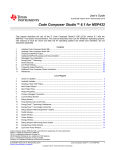
The software for this application is implemented in three levels as shown in Figure 6. The I2C access level
and the PMBus level are independent of the slave device. The application level is specific to the slave
device being used and consists of an initialization routine call followed by PMBus function calls. The
demonstration package included can, therefore, be used with any PMBus-compatible slave device with
minor changes in the application level.
Application Level
Initialize PMBus Master
PMBus Function Call
PMBus Level
Decide Protocol of Issued Command
2
I C Function Call
2
I C Access Level
Transmit Command Byte
Read Back Data From Slave
Figure 6. Software Architecture
The application level contains the PMBus function calls and the user-issued commands that are passed
as arguments. The PMBus level processes the commands it receives from the application level. Note that
all PMBus commands are defined by two parameters – the Protocol Format and the Command Code. The
Protocol Format parameter defines the I2C action that needs to be performed to execute the command (as
explained in Section 2.2). For example, Read Word format indicates that one byte is transmitted and two
bytes are received. The Command Code parameter is the hexadecimal byte that indicates which
command should be executed. For example, the command to read the input voltage is 0x88. The
summary of command codes in the form of hex bytes can be found in the PMBus Specification Part II –
Appendix I.[3]
The PMBus function decides to which of the defined Protocol Formats the command belongs and the
associated Command Code. All 126 PMBus commands defined in the standard (except user-defined
commands) have been classified under the previously mentioned formats, sorted in a header file to lessen
overhead. Based on the Protocol Format decision, the I2C functions are called and the Command Code is
transmitted.
The PMBus function also implements PEC as an added feature for optional use. Users who need PEC
implementation in the host microcontroller can select the appropriate file that allows for PEC capabilities.
Generating the PEC byte involves invoking the CRC-8 algorithm provided in a function. The CRC function
performs an XOR operation on the input data stream with the CRC-8 polynomial C(x) = x8 + x2 + x1 + 1.
This calculation is done in the order bits are received and also can be considered a brute force polynomial
division technique. The algorithm used to calculate the CRC byte is modified from the application report
CRC Implementation With the MSP430.[2]
PMBus master devices that implement PEC have either prior knowledge of whether or not the slave
supports the feature, or they are expected to determine this by reading information from the slave. The
master transmitter generates the PEC byte and inserts it at the end of the transmit data stream. If the PEC
byte is not acknowledged by the slave, then the transaction is considered invalid.
6
PMBus Implementation Using the MSP430 USCI
SLAA386A – January 2008 – Revised February 2008
Submit Documentation Feedback
www.ti.com
Example Application: Using the UCD9112 Synchronous Buck Controller Slave
If the master is receiving, then it generates the extra clock cycles needed to receive the PEC byte from the
slave as the last byte of the transaction. Master receivers can then check the validity of the PEC byte by
generating their own PEC and comparing it to the one received from the slave device.
PMBus slave devices that implement PEC must be able to respond to master devices with or without PEC
support. Slave transmitters must have the capability of generating PEC bytes and inserting them as the
final byte of any transaction if requested. Slave receivers must be able to accept the PEC byte, check to
see if the byte is valid or not, and respond with an ACK/NACK accordingly.[1]
The PMBus layer also supports alert response and control functionality by configuring two I/O pins for the
SMBALERT and CONTROL signals. The SMBALERT line is configured to trigger an interrupt on high-low
transitions. The port ISR services the interrupt and returns to the application level for further processing.
Implementing alert response functionality using the port ISR ensures better system efficiency as it
eliminates the need for polling. The CONTROL line is configured as active high but needs the
OPERATION command to turn the device on. Consequently, the port pin configured for use as the control
line is driven high in the PMBus initialization routine.
The I2C access level consists of an initialization routine that configures the USCI in I2C mode and the
functions needed to perform I2C transactions. I2C functions are used to check if the slave device is
present, verify if the bus is free, or send and receive one to n bytes based on commands from the PMBus
layer. All I2C functions are executed in low-power mode 0 (LPM0) and are optimized to work using ISRs.
This layer also implements a timeout capability using Timer A. The timeout feature is added to ensure that
slower slave devices do not hold the clock for any more than ttimeoutmax = 35 ms. If the timer expires, the
timer ISR resets the USCI module and exits low-power mode. A port pin (P5.1 connected to LED on target
board) is turned high and a flag is set to indicate that timeout has occurred. The user can add further
timeout handling capabilities as needed. Sourcing Timer A from ACLK (32-kHz crystal) allows the MSP430
to be in LPM3 for maximum power savings. For more details on using the USCI module as an I2C master
device, see the application report Using the USCI I2C Master.[4]
4
Example Application: Using the UCD9112 Synchronous Buck Controller Slave
The UCD9112 buck controller device is a part of the UCD911x family of digital power controllers. This
family of controllers provides PMBus support including support for features such as the alert response,
control signal, and PEC. The device was chosen because it can be configured easily and supports almost
all major PMBus commands. The demonstration application uses the UCD9112 Dual-Phase Synchronous
Buck Digital Controller Evaluation Module (UCD9112 EVM), which provides convenient test points and
output headers for PMBus lines.[10] A list of compatible commands and data format details are provided
in the document PMBus Support in UCD911x Family of Digital Power Controllers.[5]
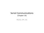
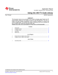
Figure 7 shows the electrical connections between the MSP430 and the UCD9112 device. The UCD9112
requires 9-V to 12-V input voltage and is capable of providing a varying output voltage of 1 V to 4 V. See
the device data sheet for more information.[6] The PMBus clock, data, and alert response lines are tied to
a 3.3-V/100-mA bus using 10-kΩ resistors. The MSP430 USCI module provides I2C support, and the clock
and data lines are interfaced to the slave device accordingly. The I2C output waveforms can be viewed
and recorded using a bus analyzer tool such as the Total Phase Beagle Protocol Analyzer
(www.totalphase.com).
SLAA386A – January 2008 – Revised February 2008
Submit Documentation Feedback
PMBus Implementation Using the MSP430 USCI
7
www.ti.com
Example Application: Using the UCD9112 Synchronous Buck Controller Slave
3.3 V at 100 mA
10 kW
XIN
32.768 kHz
10 kW
10 kW
UCB0SDA
DATA
UCB0SCL
CLK
XOUT
P1.4
VIN
10 V to 12 V
ALERT
UCD9112
EVM
MSP430xG461x
P4.2
CONTROL
VOUT
1 V to 4 V
P5.1
Figure 7. MSP430 PMBus Interface to UCD9112
Port pins P1.4 and P4.2 are used for the SMBALERT and the CONTROL lines. P1.4 interrupt (P1IE) is
enabled to trigger on high-low transitions. The control line is configured as an output and is driven high by
the MSP430 in the initialization routine. This is because the slave device is configured to turn its output on
(or off) based on both the control line and the reception of the OPERATION command. Therefore, the
device provides the specified output only when the control line is high and the OPERATION command
instructs the output unit to be turned on.
Care should be taken to avoid changing device parameters by writing to registers while the device is in
operation. If a system fault occurs, the slave device pulls the alert line low and records the source of the
fault in the status register. The status register can be read, and the CLEAR_FAULTS command can be
sent to inform the slave device that the master has acknowledged the fault. On clearing the fault (or if the
fault condition no longer exists), the alert line is released. The slave device also provides PEC functionality
and can generate/validate PEC bytes as needed. These key features are illustrated using demonstration
application code as explained in Section 6.
8
PMBus Implementation Using the MSP430 USCI
SLAA386A – January 2008 – Revised February 2008
Submit Documentation Feedback
www.ti.com
Function Description
5
Function Description
This section is divided into two subsections based on the software level the functions service.
5.1
USCI I2C Interface Functions
The USCI I2C functions are derived from those used in Using the USCI I2C Master [4]. These functions
are collectively available through the file I2Cfunctionset.c. The function prototypes are declared in the
header file TI_USCI_I2C_master.h.
5.1.1
TI_USCI_I2C_Init (Slave_Address,Prescale)
This function initializes the USCI module in I2C mode. It is called once through the PMBus initialization
subroutine. The following parameters are passed as arguments to this function:
Name
Description
Slave_Address
Device address of the slave
Prescale
This parameter is used to compute the desired baud rate. It is computed as the quotient of DCO
frequency when divided by the prescale parameter.
The USCI I2C clock is configured to operate at ~58 kHz (default DCO frequency/18) using this function.
5.1.2
TI_USCI_I2C_Slave_Present (Slave_Address)
This function detects the presence of a slave. The following parameter is passed as an argument to this
function:
Name
Description
Slave_Address
Device address of the slave
The return value is the result of the operation. The function returns a zero if the slave is present and has
acknowledged and a non-zero value if the slave is absent or not ready to acknowledge. This function also
can be used to poll slave devices that are slow in responding to the master. If there are no slave devices
connected to the bus, then the master device is trapped in a while loop and the LED is toggled rapidly
until the issue is resolved.
5.1.3
TI_USCI_I2C_NotReady ()
This function takes no parameters and returns zero, if the I2C bus is not busy. If the I2C bus is busy, then
it returns a value different from zero. It can be used to poll the I2C lines to indicate the status of an
ongoing transaction.
SLAA386A – January 2008 – Revised February 2008
Submit Documentation Feedback
PMBus Implementation Using the MSP430 USCI
9
www.ti.com
Function Description
5.1.4
TI_USCI_I2C_Transmit (Byte_CountTx, *Tx_Array, Byte_CountRx, *Rx_Array,unsigned char
*AckPointer)
This function initializes all the variables necessary to perform a transmit operation. In cases where the
transmit operation needs to be followed by a restart and a receive operation, additional parameters must
be initialized. The function first checks to see if the last two parameters – Byte_CountRx and Rx_Array are
defined. If these parameters are non-zero values, the USCI module is configured to transmit the required
number of bytes and send out an I2C restart condition, which is then followed by a receive operation. If the
last two parameters are zero, then the USCI module is configured to perform a 'transmit only' operation.
The *AckPointer variable is used to return the status of the I2C transaction. A zero is returned if the
transaction was successful (ACK); otherwise, a one is returned (NACK).
This function also initializes Timer A at the start of transmit operation. The timer is set to expire at 35 ms
(timeout functionality of PMBus) if no activity occurs on the I2C bus during that period. It uses ACLK as the
clock source. The following parameters are passed as arguments to this function:
5.2
Name
Description
Byte_CountTx
Number of bytes to be transmitted
*Tx_Array
Pointer to the array of values that are to be transmitted. Because I2C communication works byte-wise, a
field of bytes is used, for example, “unsigned char” values.
Byte_CountRx
Number of bytes to be received. This parameter is defined only if an I2C receive operation is necessary;
otherwise, a zero is passed.
*Rx_Array
Pointer to the array used to store the received values. Because I2C communication works byte-wise, a
field of bytes is used, for example “unsigned char” values. This parameter is defined only if an I2C
receive operation is necessary; otherwise, a zero is passed.
*AckPointer
Pointer to store the status of the I2C operation (ACK/NACK).
PMBus Interface Functions
There are two files that implement the PMBus interface, one that uses PEC (PMBus_PECfn.c) and one
that does not (PMBusfn.c). One or the other should be used in a given PMBus application, depending on
whether or not PEC functionality is to be used. The files are identical, except that the PMBus_PECfn.c file
includes an extra function to generate the PEC byte. Similarly, there are two header files, PMBUS.h and
PMBUS_PEC.h. The latter should be used if PEC functionality is needed. The
PMBus_Init (Slave_Address) function is common to both files.
5.2.1
PMBus_Init (Slave_Address)
This function must be called only once at the start to initialize the MSP430 for PMBus functionality. This
includes initializing two GPIO pins for the alert and control functionality. Also, the USCI_Init() function is
called to initialize the USCI module. This function checks for the presence of a slave device using the
USCI_Slave_Present() function that is repeatedly called in a while loop until the slave device
acknowledges the address. Also, if there are no slave devices connected to the bus, then the master
device is trapped in a while loop and the LED is toggled rapidly until the issue is resolved. The following
parameter is passed as an argument to this function:
10
Name
Description
Device_Address
Device address of the slave
PMBus Implementation Using the MSP430 USCI
SLAA386A – January 2008 – Revised February 2008
Submit Documentation Feedback
www.ti.com
Function Description
5.2.2
PMBus (Command_Byte,RW_Flag,Message,*Received_Value)
This function implements the PMBus software stack that is used to control the hardware access or I2C
layer. It includes the necessary functionality to determine the Protocol Format and the Command Code of
the PMBus command passed from the application level. The Command Code is determined using a
lookup table defined in the variable list_of_commands. The look-up table sorts the PMBus commands by
the order of the Protocol Format they belong to. For example, all Read Byte commands are allocated to
the first Protocol Format. Once the Protocol Format is determined, switch-case logic is used to call the I2C
functions that are needed to implement the command. For example, if the READ_VIN command is passed
from the application level, the PMBus function determines the Command Code (0x88) needed to process
this command and the Protocol Format it belongs to (Read Word). The function then proceeds to call the
I2C transmit operation and to pass all the parameters needed for the transaction.
In case of Write Byte/Word commands, the bytes to be written to the slave device are processed and
presented as a part of the transmit buffer to the USCI module. The function also sets the master device in
LPM0 when I2C transactions are being carried out. If a receive operation has been performed, the function
returns the received data bytes through a pointer to the application level. The following parameters are
passed as arguments to this function:
Name
Description
Command_Byte
This is the actual PMBus command as passed by the user, e.g., READ_VIN. It corresponds to an index
value in the PMBus lookup table. It is used to determine the Protocol Format and the Command Code of
the specified PMBus command. A list of allowed PMBus commands can be found in Power Management
Bus (PMBus) Specification Part I and II [3] and those compatible with the UCD9112 device can be found
in PMBus Support in UCD911x Family of Digital Power Controllers.[5]
RWFlag
This parameter is used only if the user command belongs to Read/Write Byte or Read/Write Word
protocol format. For example, VIN_OV_WARN_LIMIT can be used as a Read Word (to read the default
value) or Write Word (to configure the new value) command. When used as a Read Word command,
RWFlag = 1, and when used as a Write Word command, RWFlag = 0.
For all other protocol formats, this parameter is 'don't care' and is passed as zero.
Message
This parameter is defined only for Write Byte or Write Word commands. It contains the data byte or word
that is to be written to the slave device. Because the parameter is of type unsigned int, a byte or a word
may be passed. If a data word is passed, it is unpacked and stored in the transmit buffer as two bytes as
I2C operations are performed byte-wise. If the byte or word is an illegal value, the UCD9112 device does
not acknowledge it (NACK).[5]
*Received_Value
This parameter is a pointer to an array that holds the received values passed by the I2C function. It is
used only if any bytes or words are to be received from the slave device. For transmit-only operations,
this parameter is a 'don't care' and is passed as zero.
The PMBus function returns the status of the I2C transaction. A successful transaction returns a zero and
a NACK is represented by a one.
5.2.3
PMBus_PEC (Command_Byte,RW_Flag,Message,*Received_Value)
This function is defined in the file PMBus_PECfn.c. Its structure is almost identical to the PMBus()
function. However, it has the additional ability to generate the PEC byte if the master is a transmitter or if
the master can check the validity of the received PEC byte (if the master is a receiver). The PEC byte is
generated (either for transmission or for comparison and validation) using the function
crc8MakeBitwise().This function is a modified version of the CRC16/CRC32 functions defined in CRC
Implementation with the MSP430.[2]
For the master transmitter, once the PEC byte is generated, it is placed as the last value in the transmit
buffer. If the slave device acknowledges this last byte, then data integrity is said to have been maintained;
else, the slave does not acknowledge (NACK) the PEC byte. This can be verified by checking the
Ack_Status variable. For the master receiver, the last value in the receive buffer is considered to be the
PEC byte (stored in the variable crc_slave_generated). A PEC byte is then generated on the master side
(in variable crc_master_generated), and the two bytes are compared. If the bytes are found equal, the I2C
data is considered valid.
The arguments passed to this function are the same as those for the PMBus() function. The function has
one return value that reflects the PEC status of the transaction. If the PEC status is 'pass', a one is
returned; otherwise a zero is returned.
SLAA386A – January 2008 – Revised February 2008
Submit Documentation Feedback
PMBus Implementation Using the MSP430 USCI
11
www.ti.com
Application Examples
5.2.4
crc8MakeBitwise (CRC,Poly,*Pmsg,Msg_Size)
This function is a modified version of the CRC16/CRC32 functions used in CRC Implementation with the
MSP430.[2] It is defined in the file PMBus_PECfn.c and is used only by the function PMBus_PEC() to
generate the PEC byte. The standard definitions used by this function are listed in the header file
PMBUS_PEC.h. The following parameters are passed as arguments to this function:
Name
Description
CRC
Initial value of the CRC byte
Poly
CRC-8 polynomial 0x07 (the '1' in the polynomial 0x107 is implied) [2]
*Pmsg
Input bit stream for which the PEC byte needs to be calculated. All bytes in the transaction, including
Address and R/W bits, are used. Start, Stop, and ACK/NACK bits are not used.
Msg_Size
Number of bytes in the input bit stream
This function returns the calculated CRC byte.
6
Application Examples
The included application examples illustrate the key features of the PMBus protocol (as described in
Section 2.2).
6.1
General PMBus Status Polling
This application file checks for presence of slave device and reads parameters such as input voltage,
output voltage, and switching frequency from the UCD9112 slave device.
The files that must be included in a project are:
• I2Cfunctionset.c
• PMBusfn.c
• Status_Poll.c
Also, the header files PMBUS.h and TI_USCI_I2C_master.h must be accessible by the project. Example
code that illustrates how device parameters are retrieved from the slave device is shown in the following
code:
void main(void)
{
WDTCTL = WDTPW + WDTHOLD;
PMBusInit(0x08);
PMBus(CAPABILITY,0,0,Capbl);
PMBus(READ_VIN,0,0,Vin);
PMBus(READ_VOUT,0,0,Vout);
PMBus(READ_FREQUENCY,0,0,Freq);
while(1);
}
12
PMBus Implementation Using the MSP430 USCI
//
//
//
//
//
//
//
Stop WDT
Initialize PMBus device
Read device capability
Read input voltage
Read output voltage
Read switching frequency
Trap CPU
SLAA386A – January 2008 – Revised February 2008
Submit Documentation Feedback
www.ti.com
Application Examples
6.2
Alert Line Implementation
This application illustrates one way the alert functionality can be implemented. The initial device
parameters are read, after which the master device is put to sleep. When the user increases the input
voltage beyond the overvoltage warning threshold (default value for the UCD9112 device is 13.20 V), a
system fault occurs. This causes the alert line to be pulled low and the port ISR to wake up the PMBus
master device. The master device then proceeds to service the fault by reading the status registers and
sending the CLEAR_FAULTS command over the serial bus. Once the fault has been serviced, the master
device returns to LPM0.
The files that must be included in a project are:
• I2Cfunctionset.c
• PMBusfn.c
• Alert_Notify.c
Also, the header files PMBUS.h and TI_USCI_I2C_master.h must be accessible by the project. The
following code illustrates this application example:
void main(void)
{
volatile unsigned int i;
WDTCTL = WDTPW + WDTHOLD;
//
PMBusInit(0x08);
//
PMBus(READ_VIN,0,0,Vin);
//
PMBus(STATUS_WORD,0,0,Status);
//
PMBus(CLEAR_FAULTS,0,0,0);
//
PMBus(VIN_OV_WARN_LIMIT,1,0,Over_Voltage);//
while(1)
{
__bis_SR_register(LPM0_bits + GIE);
//
PMBus(STATUS_WORD,0,0,Status_Fault);
//
for(i=0;i<0x7FFF;i++);
//
//
//
PMBus(CLEAR_FAULTS,0,0,0);
//
P5OUT =0;
//
P1IE |= BIT4;
//
}
}
Note:
Stop WDT
Initialize PMBus device
Read initial Vin <13.20V
Read initial status - no faults
Clear any existing faults
Read Vin threshold value ~13.20V
Enter LPM
Read status - fault indicated
SW Delay for Vin to settle
PLACE BREAKPOINT HERE
Remove fault condition, Vin<13.2V
Clear all faults
LED off
P1.4 (Alert) Interrupt enabled
An alert condition is repeatedly generated as long as the fault exists. Therefore, while
creating the fault condition, maintaining the voltage above the warning threshold for long
periods may result in multiple or nested alerts.
SLAA386A – January 2008 – Revised February 2008
Submit Documentation Feedback
PMBus Implementation Using the MSP430 USCI
13
www.ti.com
Application Examples
6.3
Control Line Implementation
This application demonstrates the use of the control line to turn the slave device on or off. The control line
functionality is typically configured using the ON_OFF_CONFIG command. The data byte 0x1E is written
using this command. This is the default device setting.[5] It indicates that the UCD9112 device is
configured to have an active-high control line and that it also needs the OPERATION command to turn on
or off the output. Initially, the OPERATION command is used to turn the output off. At this time, reading
the output voltage returns a result of ~0 V (0x0044). Then, the VOUT_COMMAND instruction is used to
configure the output voltage to ~1 V (default value = 0x080D). The OPERATION command turns the
device on. Now, when the output voltage is read back, it is shown to be the previously set value of 1 V
(~0x0800). This application thus illustrates how to turn the slave device output on or off using software
commands. Note that the device has a specified rise and fall time (time taken for the output unit to turn on
or off). If the Vout parameter is read before this specified time, it may reflect an incorrect value. A small
delay has been added in the example code to prevent this.
The files that must be included in a project are:
• I2Cfunctionset.c
• PMBusfn.c
• ON_OFF_Control.c
Also, the header files PMBUS.h and TI_USCI_I2C_master.h must be accessible by the project. The
following code illustrates this application example:
void main(void)
{
WDTCTL = WDTPW + WDTHOLD;
PMBusInit(0x08);
PMBus(ON_OFF_CONFIG,0,0x1E,0);
PMBus(OPERATION,0,0x00,0);
PMBus(OPERATION,1,0,Oprn);
for(i=0;i<2000;i++);
PMBus(READ_VIN,0,0,Vin);
PMBus(READ_VOUT,0,0,Vout);
PMBus(VOUT_COMMAND,0,0x080D,0);
PMBus(OPERATION,0,0x80,0);
for(i=0;i<2000;i++);
PMBus(READ_VOUT,0,0,Vout);
PMBus(OPERATION,0,0x00,0);
while(1);
}
14
PMBus Implementation Using the MSP430 USCI
//
//
//
//
//
//
//
//
//
//
//
//
//
Stop WDT
Initialize PMBus device
Active high, OPERATION command
Turn Unit Off (o/p =0V)
Read back oprn. status
Delay for Vout to settle
Read Vin
Read Vout ~0V
Configure output voltage = ~1V
Turn Unit On, Margin off
Delay for Vout to settle
Read Vout ~1V
Turn Unit Off (o/p =0V)
SLAA386A – January 2008 – Revised February 2008
Submit Documentation Feedback
www.ti.com
Code Size
6.4
Packet Error Check Implementation
This application is a simple illustration of how PEC is implemented using the PMBus function. A
READ_VIN command is used to read three bytes of information – the two bytes that represent the input
voltage and the PEC byte. If the PEC byte is found valid (by the PMBus_PEC() function), the
operation_result parameter holds a value of one, otherwise it is zero. A successful transaction (valid PEC)
is indicated by toggling the LED.
The files that must be included in a project are:
• I2Cfunctionset.c
• PMBus_PECfn.c
• PEC_Check.c
Also, the header files PMBUS_PEC.h and TI_USCI_I2C_master.h must be accessible by the project.
void main(void)
{
WDTCTL = WDTPW + WDTHOLD;
// Stop WDT
P5DIR |= 0x02;
PMBusInit(0x08);
// Initialize PMBus device
Operation_Result=PMBus_PEC(READ_VIN,0,0,Vin);// Read input voltage
if (Operation_Result==1)
{
while (1)
{
P5OUT ^= 0x02;
for (i = 0; i < 0x4000; i++);
}
}
while(1);
// PEC byte valid?
// Toggle LED
// SW Delay
// Trap CPU
}
7
Code Size
Table 2 shows the code size for the included examples. The code was complied using IAR Embedded
Workbench KickStart for MSP430 V 4.09A with low optimization settings.
Table 2. Code Size (IAR)
8
Files
Code Size (Bytes)
I2CFUNCTIONSET.C
470
PMBUSFN.C
478
PMBUS_PECFN.C
900
API FILES
~80
References
1.
2.
3.
4.
5.
6.
7.
System Management Bus (SMBus) Specification V2.0 (www.smbus.org)
CRC Implementation With the MSP430 (SLAA221)
Power Management Bus (PMBus) Specification Part I and II, Version 1.1 (www.pmbus.org)
Using the USCI I2C Master (SLAA382)
PMBus Support in UCD911x Family of Digital Power Controllers (SLUA427)
UCD9112 Digital Dual-Phase Synchronous Buck Controller data sheet (SLVS711)
I2C-Bus Specification and User Manual, NXP Semiconductors, 2007
(http://www.nxp.com/acrobat/usermanuals/UM10204_3.pdf)
8. MSP430x4xx Family User's Guide (SLAU056)
9. MSP430xG461x data sheet (SLAS508)
10. UCD9112 Dual-Phase Synchronous Buck Digital Controller Evaluation Module (SLUU295)
SLAA386A – January 2008 – Revised February 2008
Submit Documentation Feedback
PMBus Implementation Using the MSP430 USCI
15
www.ti.com
Appendix A
Appendix A Associated Files
The following files are included in the associated zip package.
Folder I – Without PEC
• I2Cfunctionset.c – USCI I2C functions
• PMBusfn.c – PMBus functions without PEC implementation
• PMBUS.h – Definitions needed by PMBus files
• TI_USCI_I2C_master.h – Definitions needed by the file I2Cfunctionset.c
• Status_Poll.c – General PMBus device parameter read
• Alert_Notify.c – PMBus Alert functionality example
• ON_OFF_Control.c – PMBus Control functionality example
Folder II – With PEC
• I2Cfunctionset.c – USCI I2C functions
• PMBus_PECfn.c – PMBus functions with PEC implementation
• PMBUS_PEC.h – Definitions needed by PMBus files
• TI_USCI_I2C_master.h – Definitions needed by the file I2Cfunctionset.c
• PEC_Check.c – General parameter read with PEC
16
SLAA386A – January 2008 – Revised February 2008
Submit Documentation Feedback
IMPORTANT NOTICE
Texas Instruments Incorporated and its subsidiaries (TI) reserve the right to make corrections, modifications, enhancements, improvements,
and other changes to its products and services at any time and to discontinue any product or service without notice. Customers should
obtain the latest relevant information before placing orders and should verify that such information is current and complete. All products are
sold subject to TI’s terms and conditions of sale supplied at the time of order acknowledgment.
TI warrants performance of its hardware products to the specifications applicable at the time of sale in accordance with TI’s standard
warranty. Testing and other quality control techniques are used to the extent TI deems necessary to support this warranty. Except where
mandated by government requirements, testing of all parameters of each product is not necessarily performed.
TI assumes no liability for applications assistance or customer product design. Customers are responsible for their products and
applications using TI components. To minimize the risks associated with customer products and applications, customers should provide
adequate design and operating safeguards.
TI does not warrant or represent that any license, either express or implied, is granted under any TI patent right, copyright, mask work right,
or other TI intellectual property right relating to any combination, machine, or process in which TI products or services are used. Information
published by TI regarding third-party products or services does not constitute a license from TI to use such products or services or a
warranty or endorsement thereof. Use of such information may require a license from a third party under the patents or other intellectual
property of the third party, or a license from TI under the patents or other intellectual property of TI.
Reproduction of TI information in TI data books or data sheets is permissible only if reproduction is without alteration and is accompanied
by all associated warranties, conditions, limitations, and notices. Reproduction of this information with alteration is an unfair and deceptive
business practice. TI is not responsible or liable for such altered documentation. Information of third parties may be subject to additional
restrictions.
Resale of TI products or services with statements different from or beyond the parameters stated by TI for that product or service voids all
express and any implied warranties for the associated TI product or service and is an unfair and deceptive business practice. TI is not
responsible or liable for any such statements.
TI products are not authorized for use in safety-critical applications (such as life support) where a failure of the TI product would reasonably
be expected to cause severe personal injury or death, unless officers of the parties have executed an agreement specifically governing
such use. Buyers represent that they have all necessary expertise in the safety and regulatory ramifications of their applications, and
acknowledge and agree that they are solely responsible for all legal, regulatory and safety-related requirements concerning their products
and any use of TI products in such safety-critical applications, notwithstanding any applications-related information or support that may be
provided by TI. Further, Buyers must fully indemnify TI and its representatives against any damages arising out of the use of TI products in
such safety-critical applications.
TI products are neither designed nor intended for use in military/aerospace applications or environments unless the TI products are
specifically designated by TI as military-grade or "enhanced plastic." Only products designated by TI as military-grade meet military
specifications. Buyers acknowledge and agree that any such use of TI products which TI has not designated as military-grade is solely at
the Buyer's risk, and that they are solely responsible for compliance with all legal and regulatory requirements in connection with such use.
TI products are neither designed nor intended for use in automotive applications or environments unless the specific TI products are
designated by TI as compliant with ISO/TS 16949 requirements. Buyers acknowledge and agree that, if they use any non-designated
products in automotive applications, TI will not be responsible for any failure to meet such requirements.
Following are URLs where you can obtain information on other Texas Instruments products and application solutions:
Products
Amplifiers
Data Converters
DSP
Clocks and Timers
Interface
Logic
Power Mgmt
Microcontrollers
RFID
RF/IF and ZigBee® Solutions
amplifier.ti.com
dataconverter.ti.com
dsp.ti.com
www.ti.com/clocks
interface.ti.com
logic.ti.com
power.ti.com
microcontroller.ti.com
www.ti-rfid.com
www.ti.com/lprf
Applications
Audio
Automotive
Broadband
Digital Control
Medical
Military
Optical Networking
Security
Telephony
Video & Imaging
Wireless
www.ti.com/audio
www.ti.com/automotive
www.ti.com/broadband
www.ti.com/digitalcontrol
www.ti.com/medical
www.ti.com/military
www.ti.com/opticalnetwork
www.ti.com/security
www.ti.com/telephony
www.ti.com/video
www.ti.com/wireless
Mailing Address: Texas Instruments, Post Office Box 655303, Dallas, Texas 75265
Copyright © 2008, Texas Instruments Incorporated