1
MCS-4000
USERS MANUAL
(Red text indicates object links. Clicking on the text takes you to that portion of the manual.)
INDEX
SECTION 1
Page
INTRODUCTION
INSTALLATION
Location/Mounting
Transformer
Grounding
Local I/O Bus
Global w/Com-5002
Sensors & Accessories
Relay-8
Digital Input-8
Analog Input-8 or 16
Analog Out-4
RTU Board
Singles Board
CIO Board
Pulse Modulated Output Board
BASIC INFORMATION & OPERATIONS
Getting Started
Keypads
Activating the Display
Adjusting the Display Viewing Angle
Screen Layout
Help
Setup
Passwords
Changing a Sensor Type
Board Numbering System - Addressing
Setting Board Types
I/O Assignment
I/O Overrides
Analog Offsets
Inversion
Alarms
Setting the Clock
Setting the MCS-4000 Address Switch
Configuring the System
3
9
10
10
10
10
11
11
11
11
13
13
13
13
13
14
14
14
15
15
15
15
16
16
17
18
18
19
20
20
21
22
22
22
MCS-4000
USERS MANUAL
INDEX (CONT.)
USING THE SYSTEM
Task Status
Summaries
Alarm History
Runtime History
Graphs
Task Settings
Task Setpoints
Analog Alarms
Digital Alarms
Float Assignments
Float Limits
Setup Menu
I/O Menu
Board Status
Schedules
Run/Stop/Monitor
Miscellaneous
Set-up Graphs
Graph Interval
Alarm Enables
Defrost Time Map
Schedule Overrides
Emergency Defrost
Page
23
26
29
30
30
31
31
32
33
34
35
36
36
37
37
40
40
41
42
42
43
44
44
SECTION 2
MCS-4000 SETUP
Introduction
Tasks Common to All Libraries
Rack Library
HVAC Library
SNGL Library
CSTR Library
Tasks Common to All Libraries
Anti-Sweat Group
Lighting Group
Unit Heater/Exhaust Fans
Options Tasks
AI Monitor Task
DI Monitor Task
RO On Rise Task
1
1
1
2
2
3
3
3
8
13
18
25
26
27
MCS-4000
USERS MANUAL
INDEX (CONT.)
Page
Options Tasks (cont.)
RO On Fall Task
RO and DI Task
Analog Out Task
Subcooler Task
Desuperheater Task
Surge Valve Task
Crossover Valve Task
Freon Sniffer Task
Assorted Options Tasks
Rack Library
Compressor Group
Condenser Fans
Temp/Defr
Satellite Compressor
Single Compressor
HVAC Library
Large/Central Packages
RTU/Small Packages
SNGL (Singles) Library
Singles Group
CSTR Library
29
31
32
34
35
35
35
36
36
39
49
55
62
67
68
87
95
105
SECTION 3
APPENDIX
Drawings
MCS-4000 Front Panel
MCS-4000 Processor Board
Relay Output Board
Digital Input Board
1
2
3
4
Analog Input Board AI-16
Analog/Digital Input Board AI-16/DI-8
CIO Board
RTUBoard
Singles Board
Pulse Modulated Output Board
Definition of Terms
5
6
7
8
9
10
11
2
MCS-4000
MULTI-FUNCTION CONTROL SYSTEM
USERS MANUAL
10/06/98
INTRODUCTION
The MCS-4000, or 4K, is a microprocessor based control system that may be used for a
wide variety of control applications. Its particular application is defined by the
software/firmware, called an algorithm library that is installed in the basic controller.
There are currently 3 libraries that deal with supermarket & refrigerated warehouse
control applications including compression systems, circuit control (temperature and
defrost), condensers, HVAC, TOD scheduling, and miscellaneous. A fourth library is
available for drug store or C-Store applications, where simple compressor control,
lighting and HVAC are required.
One 4K may be used to control the complete operation of a Rack, or single Condensing
unit, or HVAC and Lighting. The MCS-4000 is capable of performing 50 assignable
tasks. A task is a defined unit of control. Any single task can have a maximum of 12
relay outputs, 12 digital inputs, 12 analog inputs, and 4 analog outputs. An example of
a task, is the control of one refrigeration circuit. This task would include the defrost
relay, temperature control relay, control temperature (analog) inputs, termination
temperature inputs or digital inputs and appropriate alarm indicators. Thus, while a
large number of I/O points could be used to control this single circuit, it is only
considered as one task to the controller, giving the MCS-4000 sufficient capacity to
handle even the largest refrigeration racks.
The MCS-4000 may be used in a totally stand-alone environment or multiple 4K's may
be connected to a COM-5002 Communications Controller or to the 6000 Advantage
color touch screen MMI (man machine interface) via the high speed COM-NET global
bus providing complete centralized local and remote communications. The COM-5002
or 6000 is also necessary to pass information between multiple 4K's, to interface with
the PMA (pulse meter adapter) which
handles up to eight utility meter pulses, and for the custom 25 character descriptions
associated with each I/O point. The 6000 Advantage provides many other features.
See the 6000 Manual for more information.
The I/O (input/output) is fully distributed. That is, the I/O boards may be located up to
5000 feet from the 4K controller. The I/O boards are connected to the 4K by the
3
RS-485 high speed Local Bus with a 3-conductor cable. There are 10 types of
input/output boards of various configurations including 3 combination boards.
The 4K can support up to 16 relay board addresses, 16 analog addresses, 16 digital
board addresses, and 16 analog output board addresses as the long as the total point
count does not exceed the following rules:
Relays
63
Digital Inputs
63
Analog Inputs
127*
Analog Outputs
31
* There are ten analog inputs that are always assumed to be present whether used or
not. They are called global inputs. They are included in the 127 total. They are: head
pressure, intermediate pressure, ambient temp, liquid temp, drop leg temp, low gas (AI),
light level #1, dew point/relative humidity, and 2 spares.
There are also 32 local transfer points: used to pass computed values within a 4K, and
32 global transfer points: used to transfer inputs between 4K's over the global bus.
The 4K utilizes a 16 line x 42 character back-lit LCD display and a unique keypad
arrangement that takes system set-up, programming, and interrogation to an
unprecedented level of ease. This controller is truly EZ-SET. The large LCD display,
two to four times larger than competitive systems, makes it possible to display
significantly more data without having to move to additional screens, and graphs have
greater resolution. The LCD back-light is equipped with an automatic time-out feature,
to pro-long the life of the display. After 15 minutes of no usage, the back-light turns off;
touching any key, except Cancel, will turn it back on.
The keypad design is actually made up of two keypads. There are 14 keys, 7 on each
side of the LCD display, that are visually connected with lines on the overlay to 14 of the
LCD display lines; similar to the concept used in banking ATM's. Then, there is a
second keypad below the screen with 20 keys for numbers, cursor movement, etc. The
combination of these two keypads with the display software produces a simple, flexible,
and very powerful user interface. The system is set-up/configured by answering a
series of questions with choices that can be selected by pressing the appropriate key at
the side of the display.
Note: With the 6000 Advantage, the 4K's may be ordered without their displays and
keypads if desired.
The system contains built-in refrigerant temperature/pressure tables, set points, and
standard names for most of the normal supermarket fixtures and refrigeration systems.
Thus, the 4K can automatically furnish about 90% of the necessary set-point
parameters based upon the answers supplied to a few questions. The user then has to
enter or modify only a few set-points to suit the specific application. I/O points may be
automatically or manually assigned. The 4K thus greatly simplifies and speeds-up the
set-up and programming process typically experienced in other controllers.
4
The 4K also features a built-in manual that is accessed from any screen by pressing the
HELP key. This is another feature that separates it from other systems. If the user
doesn't understand a particular screen or question, simply pressing the HELP key
provides the explanation. The documentation is always at hand, it can't "walk away".
Figure 1 illustrates the interconnection of the MCS-4000 and its I/O boards on the Local
Bus and the ADV-6000 (or COM-5002) on the COM-NET Global Bus.
FIGURE 1 - MCS-4000 / ADV-6000 COM-NET COMMUNICATIONS
5
The CPU board utilizes a Hitachi 64180 microprocessor running at 6 MHz. 256K of
EPROM is provided for program storage and 256K of battery backed ram for temporary
data storage. It has two communications ports; the local I/O bus (RS-485 @ 19.2
Kbaud) and the Global COM-NET communications bus (RS-485 @ 38.4 Kbaud ). A
reset switch is provided to re-boot the system.
Two alarm outputs are provided to drive a remote audible (SONALERT) alarm, and a
visual alarm (flashing light). One alarm input is provided for remote silencing of the
audible output.
Power requirements are 1 amp @ 115/230 volts AC (fused, user selectable) at 50/60
Hz. The environmental limitations are 32 F to 148 F, 95 % RH non-condensing for the
CPU. This range is limited by the LCD display; below these temperatures, the LCD
blinking speed will decrease, and ultimate failure may occur; above these temperatures,
it will turn black. When the temperature drops below the upper limit, the display will
operate normally. The I/O boards are rated from -40 F to 150 F.
The transformer/terminations module is located in the rear section of the enclosure (or
is provided separately). Connections are provided for 230/115 VAC. The MCS-4000
will operate over a voltage range of 90 volts to 245 volts. Varistors are provided for
surge suppression. An additional terminal block is provided for field wiring connections
for the alarm outputs/inputs, and for the local and global buses.
A dip switch is located on the CPU board to set the 4000 controller address and other
options.
The viewing angle of the display may also be adjusted with a potentiometer located at
the left side of the CPU board.
The MCS-4000 is mounted in a 10.25 x 12 x 4.5 in. metal enclosure with a locking door.
It weighs 6 lbs. The MCS-4000 can also be purchased on a surface mount frame,
without the enclosure, or in a 2.5" deep enclosure, for OEM mounting in existing
cabinets. These configurations are provided with a cable harness, 10 feet in length,
with connectors at one end, and a transformer that may be mounted where convenient
in the OEM cabinet.
There are 10 types of I/O boards available for the MCS-4000; rela y output, digital input,
analog/digital input 8 or 16, analog output, analog input 16 with 8 digital inputs, a special
HVAC RTU board, a singles condensing unit board, a CIO (combination input/output)
board, and a pulse/solid state relay driver board. They are connected to the 4000 by
the local RS-485 bus, which is a 2 wire plus ground cable, that may be run in star or
daisy chain fashion. The I/O boards can be located as much as 5,000 feet from the
MCS-4000. Each board has a 16 position rotary switch that is used to set the board
address. Each board has a RED LED that indicates when the local bus is transmitting
6
and a GREEN LED for Power. Power is supplied to each board via a 230/115VAC to
24 volt center tap transformer that is field mounted along with the I/O board in the
desired location. The input power to the board is fused at 3 amps. The I/O boards are
mounted in individual rack assemblies that allow stacking of the boards, if desired, to
reduce mounting space requirements, or they may be flat mounted. Cabinets are also
available that will accommodate 2, 5, or 8 I/O boards with pre-wired transformers
included. The MCS 4000 may be mounted on the front of the 8-card cabinet, if desired.
Custom cabinets are also available.
The relay output board (RO-8) contains 8 relays rated at 3 amps at 240 volts with NO
and NC contacts. Removable Phoenix connectors are provided for field wiring to the
relays and for the local RS-485 bus and the power input wiring. All connectors are
sized such that high voltages cannot be accidentally plugged into low voltage sockets.
All relays are fused at 3 amps. Spare fuses are provided on the boards. A three position
computer/manual-on/manual-off switch is provided for each of the relays. The board
may also be ordered without the switches, if desired. A red LED indicates the on/off
state of each control point; the software makes the LED reflect the control state
correctly whether the point is inverted or not. That is, if the LED is ON, the controlled
device is ON. The dimensions of the RO board are 13 x 4 x 1 inches, with a weight of 1
lb.
The digital input board (DI-8) contains 8 inputs that monitor from 24VAC to 280 VAC.
For 300 volts and above, an isolation relay or DIM module of the appropriate voltage is
required. Note: if used with dry contacts, an external power source must be supplied.
Removable Phoenix connectors are provided for field wiring to the inputs and for the
local RS-485 bus and the power input wiring. A red LED indicates the on/off state of
each input. The dimensions of the board are 13 x 4 x 1 inches, with a weight of 1 lb.
The analog/digital input board (AI-8 & AI-16) can be ordered with 8 or 16 inputs at 0-6
VDC with 10-bit resolution. Removable Phoenix connectors are provided for field wiring
to the inputs and for the local RS-485 bus and the power input wiring. There are a set of
switches for each input that allows the input to accept the standard Com-Trol
temperature (3.3k thermistor) and pressure transducers (12volts dc), or 10k thermistors,
or the AD590 solid state sensor. 5 volts DC is also available to drive other pressure
transducers. A jumper indicates whether the board is being used for analog inputs only,
or analog and digital inputs (dry contact only). The dimensions of the board are 13 x 4 x
1 inches, with a weight of 1 lb.
7
The combination analog and digital input board (AI-16/DI-8) has the same analog
capabilities as stated above with 16 inputs, but the 8 digital inputs are dry contact only,
with the board supplying the necessary voltage.
It has the same physical
characteristics as the other boards. Analog inputs on this board may not be used for
dry contact DI's due to addressing conflicts.
The analog output board (AO-4) contains 4 outputs, with 8-bit resolution, of 0 to 5, 0 to
10, 0 to 15 and 0 to 20 VDC, jumper selectable for each output. Removable Phoenix
connectors are provided for field wiring to the inputs and for the local RS-485 bus and
the power input wiring. The dimensions of the board are 13 x 4 x 1 inches, with a
weight of 1 lb.
The RTU board contains 6 relay outputs for a fan, 2 cool, 2 heat, and 1 damper. It has
1 analog output for modulating dampers. It has 8 inputs for analog/digital inputs such as
zone, outside, supply air, and return air temperatures or digital inputs such as air
flow/fan proof. This board is normally used for the small RTU selection in the HVAC
algorithm library but may be used for other applications as appropriate. It has the same
physical characteristics as the other boards.
The Singles board has 4 relay outputs, 4 digital inputs (same characteristics as DI-8
board), and 8 analog inputs. It has the same physical characteristics as the other
boards.
The CIO board has 8 relay outputs that are individually jumper selectable for normally
open or normally closed operation. It has 8 inputs that may be used for analog or digital
inputs (dry contact) as explained previously. Physical characteristics are the same as
for all other I/O boards.
The Pulse/Solid State Relay Driver board has four outputs that can drive solid state
relays for pulsed output applications such as anti-sweat heaters or pulse type expansion
valves.
Up to ten solid state relays can be driven off of each output. Physical
characteristics are the same as for all other I/O boards.
The MCS-4000 is UL listed/recognized and its I/O boards are UL recognized. It
also has CSA approval.
8
INSTALLATION
An MCS-4000 Installation Manual is available and should be used in conjunction with
the following information to achieve the best results.
Location/Mounting
The MCS-4000 can be rack mounted or wall mounted, both in it's own enclosure or in
the optional OEM surface mount frame or shallow box configurations. The unit should
be mounted at or slightly above eye level to provide the best viewing angle for the LCD
display. The OEM package consists of the processor unit mounted on a standard door
with a special frame that can be mounted to the front of the control cabinet through an
opening of 10.5" x 12.5". The transformer can then be mounted inside of the OEM
control cabinet and connected with the supplied cable. A metal shield is attached to the
back of the processor board to prevent electrical noise from getting into the system, or
damage during installation/servicing. The shallow box version, 2.5 inches deep, can
also be used in a similar fashion, but attached to the interior or exterior surface of the
rack cabinet.
The I/O boards should be located as close to the load/item being controlled or
monitored as possible to reduce wiring costs; especially the high voltage control and
monitoring wiring. The rack mount provides a quick and secure mounting. All
connectors are removable, which can be handy in tight spaces or if replacement is
necessary. Be sure to utilize the proper type and size of wire as outlined on the
installation prints. The I/O boards are rated from -40 to 150 F, thus may be mounted in
outdoor equipment in most instances.
The rack/card mounting brackets allow the I/O boards to be mounted in a vertical
side-by-side, or horizontal stacked fashion, to reduce the area that the boards occupy.
Running a plastic gutter below or to the side of the boards produces a neat/functional
installation. Wiring to the connectors should be neatly tie wrapped in groups that
correspond to each removable connector. This will enable the connectors to be
removed more easily, and keep the wiring "flexible", so that it can be moved out of the
way when the board is removed from the rack. If sufficient space is available they can
also be ordered for flat mounting with stand-offs already pressed into the board.
If the optional COM-5002 is being utilized, it can be piggy-backed to one of the 4000
units of the surface mount frame variety (as long as sufficient depth is available), or in
the deep box, or it may be mounted in a separate enclosure and be located where
convenient.
9
Transformer
The transformer for the I/O boards is 24-volt center tapped and can operate up to five
boards. Only transformers supplied by Com-Trol may be used. Make sure that you wire
the transformer as indicated on the installation prints.
Grounding
Proper grounding is essential for reliable operation of electronic equipment. Follow the
installation prints for grounding.
Local I/O Bus
The local I/O bus connects all the I/O boards associated with one 4000 to it. One 4000
can support a maximum of 64 I/O boards (16 RO, 16 DI, 16 AI- 8, or 8 AI-16, and 16
AO). The bus is a 2 wire plus ground 22-gauge cable that may be run in a star or daisy
chain pattern. Each I/O board must be addressed by setting the rotary switch (0 to F,
which corresponds to 1 to 16) located on each board. Boards must be addressed
starting at 0 (= board #1) and proceed in order up to the maximum number of each type.
Global Bus w/COM-5002
The Global bus must be wired when the optional COM-5002 or 6000 Advantage is
used. Each MCS-4000 is connected via the global bus to the COM-5002 and 6000 in
the same manner as the I/O boards are connected to a 4000. One COM-5002 or 6000
will support up to 16 MCS-4000s. Each 4000 must then have its address DIP switch set:
CAUTION
10
Sensors & Accessories
The standard sensors and accessories available with other Com-Trol products are
available with the MCS-4000. They include standard temp sensor (-50 to 150F), high
temp sensor (50 to 250F), 0 to 100 psi, 0 to 200 psi, 0 to 500 psi, and 0 to 1000 psig
pressure transducers, humidity sensor, dew point sensor, and light level sensor (0 to
300 FC). See the installation drawings for further information.
Relay-8
The Relay-8 board contains eight relay outputs with or without manual override
switches. The RO-8 relays are rated at 3 amps at 250 volts. Both normally open and
normally closed contacts are provided. See the installation prints for the appropriate
connections for your application. The removable Phoenix connectors will accept wire up
to 10 gauge. Use the smallest wire appropriate for the load. A flexible jacket is
preferred. See the installation prints for recommended wire and sizing.
Digital Input-8
The DI-8 will accept 24 vac to 280 vac. If 440 volts is present, then an interposing relay
with the appropriate coil voltage, or a Com-Trol DIM (digital input module) of the proper
voltage must be used to produce a dry contact. For use with dry contacts, an external
voltage source must be used.
Analog Input-8 or 16
The analog/digital-input board can be ordered with 8 or 16 inputs. It may be used for
various analog sensors or for digital inputs, dry contact only.
NOTE: If used for dry contact DI's, the input must still be treated like an analog input.
Refer to Com-Trol Tech Note #95001 and the installation drawings.
There is a jumper to tell whether the board is being used for analog inputs only or
analog and digital. There are two switches for each input to support various types of
sensors.
The following table illustrates the switch settings and the sensor type
supported:
11
Note: These switches are found on all I/O boards with analog/digital input capabilities,
and there are two switches per input.
Note: There is a 12vdc and 5vdc terminal on alternating connectors. The 5vdc terminal
is used with the Eclipse Transducer. Make sure the correct voltage source is being
used.
12
Analog Output-4
The analog output board will drive from one to four devices. There is a jumper pin for
each output that must be set to the desired output range, 0-5, 0-10, 0-15 & 0-20 vdc. It
is shipped with the pins set at 0 to 10 volts. See the installation drawings for type and
size of wire, and restrictions.
RTU Board
The RTU board has all the inputs and outputs normally associated with the operation of
a typical small RTU unit on it, as described previously. It has the same analog circuitry
as the AI-8 and AI-16 boards. See the installation prints for wiring hookup.
Singles Board
The Singles Board has all the inputs and outputs normally associated with the operation
of a typical condensing unit on it, as described previously. It has the same analog
circuitry as the AI-8 and AI-16 boards, but dry contact DI’s are not available as it has 4
high voltage DI inputs on it. See installation prints for wiring hookup.
CIO Board
The CIO board has 8 relays and 8 analog inputs. Jumpers must be set for
normally open or normally closed contact operation for each relay. It has the same
analog circuitry as the AI-8 and AI-16 boards. See installation prints for wiring hookup.
Pulse Modulated Output Board
The pulse modulated output board provides 4 drivers that can operate solid state relays
(not to be used to drive coils/contactors). Normal application is in conjunction with
Com-Trol’s anti-sweat heater control panel. See installation prints for wiring hookup.
13
COM-TROL MCS-4000
BASIC INFORMATION & OPERATIONS
Getting Started
The following information is provided to assist the first time user with the basic
operations associated with the MCS-4000. For further information, refer to the Users
Manual and Installation Prints.
Keypads
The 4000 has two keypads that are part of the front panel overlay (refer to Appendix A,
Figure 1). The top keypad consists of 14 keys, 7 on each side of the LCD. Each of
these keys points to two lines on the display. These keys are used to select the desired
item displayed on the LCD screen; the item indicates selection when it is placed in
inverse video (blue lettering with white background). Sometimes these keys will be
used to 'toggle' options in the setup procedure.
The lower keypad consists of 20 keys that include the numerical keys 0 to 9, a decimal
point, a minus or dash, the 4 directional arrow keys, the HELP key, the ESCAPE key
(normally used to backup between menus or exit screens), the CANCEL key (used to
acknowledge alarms and to cancel an entry), and the ENTER key (which normally acts
to save the entry).
Normal usage requires the pressing of the appropriate side key on the upper keyboard
to select a menu choice, then pressing ENTER on the lower keyboard to activate the
choice.
KEY instructions for each screen are given on the next to the bottom line and on the
HELP screens.
Activating The Display
The liquid crystal display, LCD, on the 4000 has an automatic shut-off feature that turns
off the display back-light if no keys are pressed for 15 minutes. It can be turned ON by
pressing any of the keys on the lower keypad except the
CANCEL key. The CANCEL key is used to acknowledge alarms.
Note: The display will also turn off if the ESCAPE key is pressed when on the Home
Menu.
Note: As long as the green 'Active' LED, located at the lower left corner of the display,
is flashing, the 4000 is alive and functioning.
14
Adjusting the Display Viewing Angle
If the display is not providing a well focused image, open the door and turn the viewing
angle adjustment knob until the display obtains the best focus (see Figure 2, Appendix
A). If the 4000 was mounted much below eye level, it may not be possible to get a wellfocused display; lowering the eye level may be necessary for best viewing in this case.
Screen Layout
The top line of the display (line 1) is normally used for the title of the screen and for
display of the name of the task currently being setup/reviewed. The bottom line (line
16) displays the software Library Type and Version that is installed in this 4000 (e.g.
Rack 1.326), the mode (running, monitor, stopped) the 4000 is operating in, the address
or Box number of this 4000 i.e. “#01", and the date and time of the clock in this 4K. Line
15 normally provides Key usage prompts. Lines 2 through 14 display information,
menus, data, etc. and are addressed by the side keys as appropriate.
Note: The system must be in the 'Running' mode to provide output control.
In the 'Monitor' mode, the inputs are processed but the relay outputs are not turned
on/off. In the 'Stopped' mode, the system does no control or monitoring. It will only
remain in the stopped mode for 1 hour.
Help
One of the unique features of the MCS-4000 is the built-in HELP information. If you do
not understand a particular screen/menu, press the key labeled 'HELP'. This will pop up
a HELP screen(s) that may consist of several pages of information concerning the
screen/menu you are currently on. Make sure you read all pages, the number of which
are shown in the upper right hand corner, by pressing the down arrow, to go from page
to page.
Setup
Before a 4000 can do anything, the 'SETUP' procedure must be completed. This
process provides the 4000 with all the information it needs to assign the necessary input
and output points, and the alarm and control set points. In many installations, especially
new construction, the 4000 will have been setup at the factory, with the program being
maintained by batteries for several months. If the Setup has not been performed, the
Main Menu 'Setup' option will be highlighted.
Note: Clear Memory before doing set-up; It is found on the 'Miscellaneous' Menu.
Failure to clear memory prior to programming the system for the first time can lead to
uncertain results.
To perform the 'Setup', certain information must be available, such as a refrigeration
schedule, plans and specifications, etc. to enable the person doing the setup to supply
answers or make correct choices required in the setup procedure. Make sure you have
this information before beginning the Setup.
15
Com-Trol also has the Setup procedure available on a diskette (or bulletin board) that
allows the user to perform the setup on a PC, and to printout an input/output board
points list. This program also allows the setup information to be uploaded to and/or
downloaded from the 4000 when direct connected from the PC to the global
communications port, utilizing an RS-232/485 adapter module, available from Com-Trol,
or it can be loaded through the COM-5002 or 6000 Advantage, when present. This
program is called EZSET2. A separate manual is provided for EZSET2.
See the ‘Setup’ section of the manual for complete information.
Passwords
Passwords are built-in to the MCS-4000 to provide some measure of security for
preventing unauthorized individuals from changing set points or performing other
operations, which can have a profound affect on the operation of the system.
Three passwords are present in the MCS-4000. They are initially set-up as
follows: Level 1 = 7777, Level 2 = 8888, Level 3 = 9999.
The high level password is necessary to perform the Setup operation, Auto Assign I/O,
Clear the program/memory, Clear the Alarm History, Edit Passwords, to change the
Run, Stopped or Monitor modes, and to setup I/O Board Types.
To change the passwords, the high level password must first be active and then the
'change code' entered. The change code is 1843.
Note: The low and high level passwords should be changed upon completion of the
installation by the responsible authority to maintain proper system security.
Note: Some items, such as 'Emergency Defrost', have the option of requiring a
password or not, posed during the 'Setup' process.
Changing A Sensor Type
Normally, the 4000 will automatically assign all the analog input sensors of the
appropriate type necessary for the application. However, in some instances it may be
necessary to change the sensor type; for example the 4000 assigns all suction pressure
transducers as 0 to 200 psi types. If a 0 to 100 psi transducer was used, the type may
be changed by selecting 'Setup' on the Main Menu, and 'I/O Menu' on the submenu.
Select ‘Analog Ins’, and then press Enter. A list of all the Tasks will then be displayed.
Select the Task that the analog input is associated with and press Enter. The first
analog will be displayed. Pressing Enter will move you through all the analog inputs
associated with this task. Stop at the one you want to change and press the left side key
pointing to ‘Type’. Next, press the up/down arrows to rotate through a list of the sensor
types available. When you arrive at the desired type, press Enter. There are 33 sensor
types as follows:
16
Reg f
Regular Com-Trol temperature sensor (-45F to 120F).
Hi F Com-Trol high temperature sensor (0 to 300F).
Reg c Regular Com-Trol temp sensor in degrees Celsius.
Hi C Com-Trol high temp sensor in degrees Celsius.
Dewp f
Com-Trol dewpoint sensor, degrees Fahrenheit.
Dewp c
Com-Trol dewpoint sensor, degrees Celsius.
Etmp f Not available at this time.
Etmp c
Not available at this time.
Johns6
Johnson Controls oil pressure transducer (6 psi trip).
Johns9
Johnson Controls oil pressure transducer (9 psi trip).
Abient Ambient temp sensor with special range.
Car 5K
Accepts the Carlyle 5k sensor built into screw comps.
P100
Com-Trol 12v pressure transducer, 0 to 100 psi.
P200
Com-Trol 12v pressure transducer, 0 to 200 psi.
P500
Com-Trol 12v pressure transducer, 0 to 500 psi.
P1000Com-Trol 12v pressure transducer, 0 to 1000 psi.
4-20ma
Yields 1-5 v; requires 250 ohm 1% resistor across input.
FtCndlCom-Trol light level sensor 0-300 foot candles.
Frost
Not available at this time.
Cfreon
Com-Trol Freon sensor; 1 to 6 volts, 0 - 2000 ppm.
Ammonia
Com-Trol ammonia sensor; `1 to 6 volts, 0-300 ppm.
Oil Pr
Differential pressure xducer; 1 to 6volts; 0-100psi.
HnsLq Hansen liquid level sensor; 1 to 6 volts, 0 to 100%.
Margau
Margaux temperature sensor; AD590.
Percnt Percent; based on 0 to 5 volt input.
Freon Freon sensor; 0 to 5 volts, 0 - 500 ppm.
P100 E
Com-Trol Eclipse pressure transducer; 5 volt; 0-100 psi.
P200 E
Com-Trol Eclipse pressure transducer; 5 volt; 0-200 psi.
P500 E
Com-Trol Eclipse pressure transducer; 5 volt; 0-500 psi.
P1000E
Com-Trol Eclipse pressure transducer; 5 volt; 0-1000 psi.
Offs f
Special purpose.
User#1
User definable; must be linear sensors.
User#2
User definable; must be linear sensors.
User#3
User definable; must be linear sensors.
User#4
User definable; must be linear sensors.
Note: Types that appear as *-**-* are spares that have not been defined.
I/O Board Numbering System – Addressing
The input and output boards and each point are referenced in various places by the
following scheme: ##-#; where the first two numbers represent the board number (from
1 to 16) and the number after the dash represents the point number (from 1 to 8). For
example: 01-1 indicates board 01, point 1.
17
Note: When an analog input board with 16 inputs (AI-16) is used, it occupies two
addresses; even though only one physical address switch is set.
Note: For boards with combinations of inputs/outputs, each type of input will occupy
that address. For Example - the AI-16/DI-8 board will occupy analog addresses 1 & 2
and digital address 1.
The board number/address is set by turning the rotary DIP switch located at the top left
corner (see Figure 3, Appendix A), with a small screw driver in the slot, or with the
fingers, when equipped with the appropriate style of switch, as indicated on the
installation prints; i.e. board 01 = 0, board 02 = 1.... board 11 = A, board 12 = B etc.
Remember that each type of board (relay, digital, analog in, analog out) can have
addresses from 1 to 16 for each 4000.
Setting Board Types
If analogs are present on board types other than AI-8, the Board Type may be selected
by selecting ‘Task Settings’ with the side key on the ‘Main Menu’, press “Enter”. Next
Select ’I/O Menu’ with side key and press “Enter”. Press the side key aligned with
‘Board Types’, Press “Enter”. You will be prompted for the high level password if not
previously entered. Use the arrow keys to move to the desired board address, press the
side key aligned with the reverse video “Select” menu item (bottom right), then use the
up/down arrow keys to rotate through the board types. The choices are AI-8, AI-16,
RTU, Sngl, and CIO. Stop on the desired type, and then press “Enter”. Continue until
all Board Types have been set. Press “Enter” again to return to the previous menu.
The I/O configuration shown on the "Summary"/"Relay", "Digital Inputs", and "Analog
Inputs", and "Analog Output" screens will now reflect the proper number of inputs
present for each board type/address.
I/O Assignment
The 4000 can provide all input/output assignment automatically, or the assignments can
be made manually.
To automatically assigned the I/O, after all tasks are set-up, select ‘Task Settings’ from
the ‘Main Menu’, and press “Enter”. Select ’I/O Menu’ and press “Enter”. Select ‘Auto
I/O Assign’ and press “Enter”. Two choices are now available, ‘Pack Tight’ or ‘Skip by
Task’.
‘Pack Tight’ assigns all the I/O point required in a predetermined order leaving no
spaces/unused points. This would give the minimum number of boards required, but
would not consider that the boards may need to be in different locations for certain
tasks.
18
‘Skip by Task’, assigns all the points required for a given task type/category, then jumps
to a new board(s) for the next Task type; i.e. condenser would be separate from
compressors, temp/defr circuits would be separate, etc. This would enable, the boards
associated with the task type to be physically located where the device is located.
Either one of these may be used with some manual assignment/re-assignment to get
the desired layout.
Manual assignment is accomplished as indicated above, but selecting ‘Relays’, ‘Digital
Ins’, ’Analog Ins’, and ‘Analog Outs’, instead of ‘Auto I/O Assign’. Each task is then
selected from the Task list displayed. The first point of the selected type will then
appear. Use the side key to select ‘Bd-Pt’, and type in the board and point number with
the number keys, with a “.” or “-” separating the board number from the point number.
Note: If an assignment is already present, remember that for Relays and Analog
Outputs, the system will not allow you to assign it to another point that has
already been assigned. You may have to use unused points temporarily to get
relays and analog outs moved around. Digital inputs and Analog inputs may be
multiply assigned, if required. An asterisk, *, will be placed after the ‘Bd-Pt’ to
indicate multiple assignment.
Note: The EZSET2 editor may also be used to assign I/O.
See EZSET2 Manual.
Assignments may be changed at any time for service or installation purposes.
I/O Overrides
Any input or output may be overridden/forced to a specified on/off state, or value (for
analog input and outputs). Overrides are useful for testing or to temporarily "fix" a bad
sensor.
Relay Override - Select ‘Task Settings’ on the Main Menu with the side key and
press “Enter”. Select ‘I/O Menu’ with the side key, press “Enter”. Select
‘Relays’ with the side key, press ”Enter”. Enter password, if prompted.
Pick the desired task from the list of tasks displayed with the side key,
press “Enter”; use the up/down arrows to get to other tasks, if not
displayed on current page. The first relay associated with the selected
task will be displayed. Use the side key to select ‘State’, then use the
up/down arrows to toggle through the choices; “Com”, “On, Off”. Com =
computer control, On = put relay in override On; Off = put relay in override
Off. Press “Enter” to secure the desired state. Proceed through rest of
relays, as appropriate; Pressing “Enter” continues through all relays
associated with the selected task.
19
Relay (or other I/O types) will remain in the selected overridden state until user
puts back to Com mode.
Digital Ins - same process as for relays, except select ‘Digital Ins’ on the
I/O Menu screen.
Analog Ins - Same process as for ‘Relays’ above except select ‘Analog Ins’ from
the I/O Menu screen and when you select ‘State’, the only choices are,
Com and On. Then, select ‘Units/Override Value’ with the side key, and
type in the desired override value you want the input to read, and press
“Enter”. Thus, it is a two step process to implement an override on an
analog input.
Analog Outs - same process as for ‘Analog Ins’.
Note: If no inputs or outputs of the category selected are associated with the task;
nothing will happen when you press “Enter”.
Analog Offsets
Analog inputs and Outputs can have an offset value (an amount that is added or
subtracted from the sensor input value before using it for control), entered if needed.
This is normally used to adjust the value of a pressure transducer or a temp sensor to
match a known good reference. The procedure used is similar to the analog override
procedure explained previously, except select ‘Units/offset’ with the side key, and enter
the desired offset value with the number keys (may be plus or minus (-)), then press
“Enter”.
Note: The temperature sensors and transducers are normally very accurate and offsets
should rarely be required. Don't assume your gauge is more accurate than the sensor;
be sure.
Inversion Relays
Relay output states and control states are defined within the 4000 software. Relay
inversion/failsafe mode is normally properly handled by the 4000 in the Setup routine.
However, there may be a few instances where the relay output needs to be inverted or
the inversion removed.
Relays specified as 'Normal', are defined so that they are wired to the normally closed
contacts, so that they fail on, such as refrigeration compressors and circuit temperature
control solenoids. Relays specified as 'Inverted' are wired to the normally open contacts
and fail off, such as defrost.
20
Select ‘Task Settings’ on the Main Menu with the side key and press
“Enter”. Select ‘I/O Menu’ with the side key, press “Enter”. Select ‘Relays’
with the side key, press ”Enter”. Enter password
if prompted. Pick
the desired task from the list of tasks displayed with the side key, press
“Enter”; use the up/down arrows to get to other tasks, if not displayed on
current page. The first relay associated with the selected task will be
displayed.
Use the side key to select ‘Inv/Inversion’, then use the
up/down arrows to toggle through the choices; “Normal” or “Invert”. Press
“Enter” to secure the desired choice. Proceed through rest of relays by
pressing “Enter”.
Digital Inputs
Digital inputs may also be inverted. Process is same as for relays, except select Digital
Ins from the “I/O Menu”.
Analog Outputs
Analog outputs may also be inverted if needed. If inverted, the output signal goes from
maximum to minimum; e.g. 10v to 0v. Follow same process as for Relays explained
previously, except select ‘Analog Outs’ from the I/O Menu.
Alarms
Various alarms are created during the Setup/programming routine. These alarms may
be altered or disabled by selecting ‘Task Settings’ on the Main Menu with the side key,
then press “Enter”. Next select ‘Analog Alms’ or ‘Digital Alms’ as appropriate, with the
side keys and press “Enter”. Next, select the Task, side key; from the task list screens
that you want to modify alarms for and press “Enter”. Use the left/right side keys for the
parameter you wish to alter, type in the desired value, and press “Enter”. Press “Enter”
again to move on to the next alarm associated with that task, or keep pressing until you
return to the task list.
When an alarm occurs, the red LED at the lower right of the display (just above the key
lock) will be ON and the horn will be sounding (unless dip switch #8 is set to ON). The
horn may be silenced by pressing the CANCEL key, while viewing the ‘Alarm History”,
which acknowledges the alarm. The Red LED will stay on however, until the alarm
condition clears.
NOTE: IF DIP SWITCH NUMBER 8 IS SET TO THE RIGHT, THE 4K ALARM HORN
WILL NOT SOUND, AND IF A 5K2 IS PRESENT, THE 5K2 HORN OUTPUT WILL NOT
SOUND (FOR ALARMS ON THAT PARTICULAR 4K). THE ALARM LED ON THE 4K
AND THE 5K2 ALARM LIGHT OUTPUT WILL OPERATE, HOWEVER.
To view the alarm history, select ‘Alarm History’, on the Main Menu. The most current
alarm will be at the top of the list, proceeding to the oldest (use down arrow to step back
through the log). The last 40 alarms are maintained. Use the right arrow to view the
‘Cleared’ and ‘Acknowledged’ time stamps.
21
Setting The Clock
If the time and date do not appear correctly at the bottom right of the display, select
‘Miscellaneous’ on the Main Menu, then 'Set Time' on the sub menu. Use the right arrow
to move to the desired element to change and type in the desired value with the
numerical keys. Press “Enter” when done to secure the change.
Note: When a Com-5002, its clock is used to set/synchronize the clocks on all 4000's
connected to it. The clocks are synchronized every hour at 5 minutes past the hour.
Setting the MCS-4000 Address Switch
If a COM-5002, Communications Controller, or 6000 Advantage is present in the
installation, then each MCS-4000 must have its address switch set to a unique value
from 1 to 16. The address switch is reached by opening the door and locating the DIP
switch at the middle right side of the CPU board (see Figure 2). Set the first 4000 at
address 01 and proceed upwards. Dip switch settings are shown on the installation
drawings. Switches 1 - 5 are used for the address. The switch setting can be verified by
looking at the bottom line of the display; 'Box01' would indicate that the 4000 had its
address switches set to 01.
Configuring the System
If a COM-5002 is present in the installation, then once the global bus is connected to all
MCS-4000 controllers and each 4000 has been setup/programmed, the system must be
configured. This is accomplished by plugging in a terminal or PC to the local RS-232
port on the COM-5k2, or by calling it up over the phone line utilizing the built-in modem.
When the system answers/connects, type in the number that represents the type of
terminal or PC you are using. The password screen will appear. Enter the password,
initially set to UEI450. The Main Menu will then be displayed. Type a 'Z' to obtain the
'Monitor Commands' menu. Select 'Configure All' and press Enter. The COM will then
start polling at address 01 over the global bus. For each 4000 that responds, the tasks
information and default names will be created for the system/task menu. This process
will be repeated for each 4000 that responds. The COM-5002 has now stored the
system configuration in its battery backed memory. If the Task or I/O configuration is
altered at anytime after this process, then it needs to be repeated to obtain the new
configuration information.
Refer to the COM-5002 Users Manual for further information on communications.
22
USING THE SYSTEM
The MCS-4000 provides the user with an abundance of information. The following
discussions deals with the screens that you will normally use once the system has been
programmed and is up and running.
Task Status
The Task Status screen provides you with the most complete data picture of what is
currently going on with each task and you will use it frequently. You may also go
directly from the selected task status screen to all items associated with it, simply by
pressing a number key between 1 and 9. These quick access keys are defined as
follows:
1 = set points
2 = schedules (if applicable to the selected task)
3 = relays
4 = digital inputs
5 = analog inputs
6 = analog outputs
7 = analog alarms
8 = digital alarms
9 = removes any computer relays overrides for the
selected task.
A typical Compressor Task status screen is illustrated below. All other status screens
are similar in structure but have the appropriate inputs, outputs, and set points
displayed for that particular task type. See setup information for each task type for
further explanation. All data on this screen is updated every 6 seconds.
To get to the task status screen, Select ‘Task Status’ from the Main Menu with the side
key, press “Enter”. Use the left/right side keys to select the desired task from the list,
and press “Enter”. If the desired task is not visible on the task list screen, push the
down arrow to get to the next page(s). The Task Status screen will then be displayed.
Rack A -25 LT-Cmp#01
Mode: Normal Run
Alarms: Clear
Suction PSI 10.0p2
Sat Suction -22.0
Initial Target
6.0
Current Tgt
7.0
Float TmpAv -12.1
Float Tgt
-12.0
01-SDIC
Ckt#1
Current Acc
76.5%
Head Press 185.0p5
Head Safety 325.0
23
--------------------------------------------------------------------------------Unit Status Monitor
% of Grp
Run,
Tdy/Yst
Comp1-1 On On
14.2% 25.6% 35.5%
Comp2-1 Off Off
28.5% 85.0% 87.2%
Comp3-1 On On
57.1% 99.9% 99.9%
^ | More Pnts, Enter next tsk,
Rack 1.334
Running
#01
<- -> More Data
8/10/95
06:10:33
The top line gives the name of the Task, either default or as customized with Ezset2
and downloaded.
The second line displays the Mode, which is the current operating state of the task
(varies by task), and Alarm, which indicates “Clear’, “Timing” or “In Alarm”. These give
you basic status at a glance.
The third line down to the dotted line displays various input and set point information.
The information displayed here varies depending upon the task type and the options
that were selected during the setup/programming process. For the example compressor
task status screen, they are as follows:
Suction PSI - The current suction pressure.
Sat Suction - The equivalent saturated suction temperature based on the
suction pressure and the refrigerant specified during set-up.
Initial Tgt - The initial target suction pressure; may float up or down if a float
temp/defr circuit was specified. See Float Assignment.
Current Tgt - The current target pressure which takes into account the float
assignment/value.
Float TmpAvg - The current float circuits average temperature Used in
conjunction with the Float Target to determine the offset applied to the target pressure.
Float Tgt - The target float temperature taken from the temp/defr circuit that is
being used for the float process.
01-SDIC - The task name of the selected float temp/defr circuit.
Current Accumulator - The current projected capacity required to meet the load as
predicted by the PID control algorithm. Determines which step of capacity/combination
of compressors is being used.
24
Head Press - The current head/discharge pressure.
Head Safety - The pressure at which compressors will start staging off for
safety purposes.
Information below the dotted line:
Unit - The name of the relay output(s).
Status - The On/Off and override status. If overridden by software, a “r” will appear
next to the on or off; if switched at the relay I/O board, a “s” will be present; and if
overridden both ways, a “b” will be displayed.
Monitor - If a monitor/proof input was selected during set-up, it will appear in this
column. It should match the relay state within 6 sec. (Unless something is getting in the
way).
% of Grp - For compressor groups, indicates the percentage of the total
capacity that each compressor represents, based upon the HP or Btuh values entered
during the set-up process.
Run Tdy/Yst -These two columns provide the calculated percentage of runtime for
each relay for today (thus far), and yesterday.
Pressing right arrows, as indicated at the bottom of the screen, will provide additional
information in these columns. This includes, the runtime and cycles for today and
yesterday, and the last on and last off and total runtime since the system was setup/reprogrammed.
Use the down arrows to get to additional relays, if necessary.
The bottom line always displays the following information:
Software Library present and its version number.
Mode - running, monitor, stopped.
Box Address
Date and Time
Remember, to save time, use the quick access keys (1-9) from this screen to get
to all additional information about this task.
25
Summaries
Summary screens provide additional ways to look at system information in several ways
that are not task specific. Selecting Summaries with the side keys from the Main Menu
brings up the Summary Menu. Items displayed here include:
Relays - displays status of all relays on a board by board basis.
Digital Ins - status of all digital inputs on a board by board basis.
Analog Ins - status of all analog inputs on a board by board basis
Analog Outs - status of all analog outputs on a board by board basis
Alarm Summary - a list of all alarms and their set points for all tasks setup on this 4K.
Circuit Summary - a list of all Temp/Defr tasks and their temperature
control set points and status.
Defrost Summary - a list of all Temp/Defr tasks and their defrost
set points and status.
Select the desired summary type with the side keys and press “Enter”.
Example screen for the I/O Summaries follows:
1 Fan 01
Relays
Board #1 RO8
On
Fan Group#01
2
3
4
5
6
7
8
The board # (1-16) and type (RO8, SNGL, RTU, CIO) are shown on the first line.
Each relay present on the board type selected is listed with the point name and the
Task Name it is associated with underneath.
The state of the relay is listed On/Off, or Lost if the I/O is not communicating.
Use the up/down arrows to get to other Relay boards and left/right arrows to get to other
board types (DI, AI, AO) if you do not want to return to the menu to select them.
The other I/O types display the same information with their appropriate state or value.
26
An example of the ”Alarm Summary Screen” follows.
Alarm Summary
Name Task Type
Now/Trip
Sate/Delay
Suctn Compr LT #01
12.0
Clear 00:00
High Suct
22.0
00:10 ANNA
Low Suct
1.0
00:10 ANNA
HedCmp
Compr LT #01
180.0
Clear 00:00
High Head
325.0
00:01 ANNA
Low Head
50.0
00:01 ANNA
CmMn01
Compr LT #01
Off
In Alm 00:16
Mon Proof
On
00:01 ANNA
Rck Oil
Compr LT #01
On
Timing 00:05
DR Oil Fail
On
00:15 ANNA
To view more alarms, press the down/up arrows.
The point name is given in the first column followed by its associated Task’s name. The
name/type of the alarm is given under the task name.
The current value or state, “Now”, is listed in the third column with the alarm setting or
state given, “Trip”, below it.
The alarm ”State” is given in the next column (clear, timing, or In Alm), with the delay
time underneath it in hours and minutes.
The fifth/last column displays how long the alarm has been timing or has been in alarm,
with the dial-out and local alarm setting underneath.
A sample screen for the “Circuit Summary” follows:
Unit
01-SDIC
02-SDFF
03-SDFF
04-RIFF
etc.
Circuit Summary
Status Target Average
On
-22.0
Defr
-10.0
Off
-10.0
Drip
- 5.0
Next Defrost
-18.5
00:00
32.0
01:00
-11.0
02:00
45.4
03:00
To view more circuits, use the down arrow. To view the individual temperature sensors
for each circuit the right arrow key (4 on each screen, maximum of 12).
The first column lists the task name for each temp/defrost circuit.
27
The ‘Status’ listed in the second column can have the following states:
On = refrigeration On
Off = refrigeration Off
Defr = in defrost (refrig off)
Drip = defrost and refrigeration off
Ovrd = manual/emergency defrost
Wash = washdown (refrigeration and defrost off for timed period)
Pdwn = pumpdown mode (defrost off)
Target - The programmed target temp. Only used for control is setup
Average - The current average of all temperature sensors on the circuit.
Next Defr - Next scheduled defrost time.
Temp1 to Temp12 - the temperature readings of sensors on the circuit.
Example screen for the Defrost Summary follows:
Unit
01-SDIC
02-SDFF
03-SDFF
04-RIFF
etc.
Defrost Summary
Status Failsafe
Drip
On
20
Defr
30
Off
30
Drip
45
Term Temp
5
48.0
5
48.0
5
48.0
5
55.0
45.6
35.0
48.0
44.5
To view more circuits, use the down arrow. To view the individual defrost times for each
circuit the right arrow key (4 on each screen, maximum of 6).
The first column lists the task name for each temp/defrost circuit.
The ‘Status’ listed in the second column can have the following states:
On = refrigeration On
Off = refrigeration Off
Defr = in defrost (refrig off)
Drip = defrost and refrigeration off
Ovrd = manual/emergency defrost
Wash = washdown (refrigeration and defrost off for timed period)
Pdwn = pumpdown mode (defrost off)
Failsafe - programmed failsafe/maximum defrost duration.
Drip - the drip/run-off time setting (refrig and defrost off)
Term - the defrost termination value (for temperature termination).
28
Temp - the lowest temperature of all sensors on the circuit that was reached at
the time of termination the last time a defrost was performed.
Time1 through Time6 - the scheduled defrost start times.
Alarm History
Each MCS-4000 can store the last 40 alarm events that have occurred. Select ‘Alarm
History’ from the Main Menu with the side key and press “Enter”. The newest is always
shown at the top of the first page. The date and time that each alarm occurred, cleared
and was acknowledged is stored for each and can be reach by pressing the right arrow.
To acknowledge all current alarms that have not been acknowledged, press the
“Cancel” key while viewing this screen. The alarms can be viewed in different
categories if desired by pressing the number keys while viewing this screen:
All Categories (1) - the default screen (all types of alarms)
Out of Operating Parameters (2) - high, low etc.
Bypasses and Overrides (3) - switches and software
Hardware Failure Indications (4) - lost boards, open/short sensors
Abnormal Defrost Terminations (5) - defrost terminating on minimum,
failsafe or override.
Note: ‘Alarm Enables’ must be set to get some of these alarms.
The following is a sample of the Alarm Summary screen:
Alarm Type
Mon Proof
Lost Relay
High Suct
All Categories
Circuit Value Tripped at
CmMn03
Off
Compr LT #01
Board #2
LOST
Suct A 35.6
Compr LT #01
18:12 08/06
18:11 08/06
04:32 08/05
etc.
The Alarm Type is shown in the first column. The point name with the associated Task
name are given in the second column. The value or state at which the alarm occurred
are given in the third column followed by the time and date at which it occurred.
Pressing right arrows will change the fourth column to the “Cleared” time and date,
followed by the “Acknowledged” time and date.
Use the down arrow to get to more pages of the alarm history.
29
Runtime History
The MCS-4000 maintains runtime and cycle information for all relays, on a board by
board basis, for the last 31 days (month). Select ‘Runtime History’ from the Main Menu
with the side key and press “Enter”. The screen will appear as follows:
Runtime History
Board 01 RO8
R.O. Pnt
8-06 Sun
Fan 01
Fan Group#01 08:31
1
Fan 02
Fan Group#01 08:31
1
Fan 03
Fan Group#01 08:31
1
Comp01
Compr LT #01 06:25
10
Comp02
Compr LT #01 08:15
2
Comp03
Compr LT #01 07:13
15
Refr01
01-SDIC
08:31
1
Defr01
01-SDIC
00:30
1
Date
8-05 Sat
24:00
0
18:45 15
06:20 22
12:25 55
20:15
6
14:55 32
22:50
2
01:00
2
The board number and board type (RO8, SNGL, HVAC, CIO) are given at the top left.
Pressing a down arrow will move you to the next board. The relay point names are
given in the first column followed by the Task Name. The current date (month, day, &
day of week) and the day before are shown on the first screen. Pressing a right arrow
will move you back in time one day at a time. Pressing the left arrow will move you to
the oldest day in the log, then forward in time from there (it is a circular log). The
runtime followed by the cycles are listed under each date. For the current day, it is the
runtime and cycles thus far in the day.
Note: If a digital proof input exists for the relay point, then the displayed information for
the runtime is from the digital input, the cycle count is still from the relay.
Graphs
The MCS-4000 logs all inputs and outputs at the selected interval (6 sec to 2 hours).
Up to 32 graphs may be set-up to display this information. At initial set-up the 4K
automatically selects the first 32 analog inputs and sets-up graphs for them. The graph
set-up may then be changed at anytime to the desired I/O points. All point types may
be graphed. The number of logging samples is determined by the memory option
purchased. The standard memory provides 143 samples for every I/O point. The
maximum is 588 (standard on products shipped after 7/98).
Note: Even though any specific I/O point may not be set-up for graphing, it is still being
logged. Thus, simply changing the set-up will bring up the stored data for that I/O point.
Note: You may go directly from any graph being viewed, to its set-up screen by
pressing “Enter” while viewing that graph.
30
A typical graph appears as follows:
Suction
Compr Lt#01
1
100.0 ---------------------- |---------------------- |-------------------- |
|
|
|
|
|
|
50.0 ---------------------- |---------------------- |-------------------- |
|
__
|
|
25.5 - - - - - _ _
_ - - -|- - - - _ _ - - |- - - - - _ _ _- - -|
|
|
0.0 ----------------------- |---------------------- |-------------------- |
07:21
07:20
07:09
|
|
|
|
The point name, task name, and graph number are given on the top line.
Pressing a down arrow will move you to the next graph. The current value is always
shown on the scale at the left side, even if it is out of range of the scale settings. The
graph will update at the selected interval while you are watching it. The current time is
at the left and proceeds back in time to the right; pressing left/right arrows will move you
back in time. The time at which you entered the graph is shown with the small
rectangular block; which provides a handy reference if you are observing the graph for
some extended time. See ‘Set-up Graphs’ for further information.
Task Settings
This selection from the Main Menu provides access to parameters that may be changed
by the user. These include:
Task Setpoints
Analog Alarms
Digital Alarms
Float Assignments
Float Limits
Setup Menu
I/O Menu
Schedules
Run/Stop/Monitor
The following discussion will cover each of these items.
Task Setpoints
Each task type has various set points/control parameters.
These set points have
default values that the MCS-4000 automatically enters during the Setup process.
31
These values can be altered at that time or at anytime in the future. Setpoints are
password protected (level 2).
To get to the Task Set points, select ‘Task Settings’ on the Main Menu with the side
keys, and press “Enter”. Next, select ‘Task Set points’ with the side key and press
“Enter”. You will then be presented with a list of all the tasks. Select the desired task
with the side key and press “Enter”. A menu of choices will be presented that varies by
task. Select the desired item with the side key and press “Enter”. Select the desired
set point to change with the side key, type in the appropriate value, then press “Enter”.
Press “Enter” again when all desired changes have been made.
Note: You can also go directly to the set point screen, by pressing a “1" while viewing
the ‘Task Status’ screen, as previously discussed.
Refer to the ‘Setup’ section of this manual for details on the various set point screens.
Analog Alarms
To change the analog alarm settings, select ‘Task Settings’ with the side key on the
Main Menu and press ‘Enter”. Select ‘Analog Alarms’ with the side key and press
ENTER. Next, select the Task from the list that you want to view/modify the alarm
settings with the side key and press Enter. The first analog alarm associated with the
selected task will then appear. Pressing Enter will move you to the next alarm and so
on until you return to the task list screen. A typical Analog Alarm screen appears as
follows:
Compr LT #01-Cmp#01
Analog Alms
High Suct
Stp
17.7 Trip Value
Suctn
Low Suct
1.0
Mins
00:10
Delay Time
00:10
Levl
ANNA
Priority (123L)
ANNA
Time
00:00
Disable Time
Cnt
0
Repeat Count
The top line displays the Task Name and Task Type & number.
The second line indicates this is an Analog Alarm screen.
32
The third line indicates the alarm type; i.e. High Suction and Low Suction.
The remaining lines are as follows:
Trip Value - The level above or below which the alarm will start timing.
Delay Time - The delay in minutes, once the alarm has exceeded the Trip Value, before
the specified alarm action will take place.
Priority - The alarm action to be taken for each phone number (123) and local
alarm output (L). A = dial out, L = Log only, N = no action,
M= morning dial out.
Disable Time - The time in hours and minutes that you want an alarm to be temporarily
disabled (maximum of 48 hours).
Repeat Count - The number of times you want the alarm to be repeated, as long
as it has not cleared, at one hour intervals, up to a maximum of 9 times.
To change any of the alarm set points, press the side key (left and/or right), type in the
change, press “Enter”. Press “Enter” again to move on to the next alarm.
Note: Some alarms will only have a high value and some will only have a low value.
Digital Alarms
To change the digital alarm settings, select ‘Task Settings’ with the side key on the Main
Menu and press ‘Enter”. Select ‘Digital Alarms’ with the side key and press ‘Enter’.
Next, select the Task from the list that you want to view/modify the alarm settings with
the side key and press Enter. The first digital alarm associated with the selected task
will then appear. Pressing Enter will move you to the next alarm and so on until you
return to the task list screen. A typical Digital Alarm screen appears as follows:
Compr LT #01-Cmp#01
Digital Alms
Mon Proof
------Mins
Levl
Time
Cnt
CmMn01
00:01
Delay Time
ANNA
Priority (123L)
00:00
Disable Time
0
Repeat Count
33
The top line displays the Task Name and Task Type & number.
The second line indicates this is a Digital Alarm screen.
The third line indicates the alarm type; i.e. Monitor Proof.
The remaining lines are as follows:
--- - Indicates not used for this alarm type.
Delay Time - The delay in minutes, once the alarm has exceeded the Trip
Value, before the specified alarm action will take place.
Priority - The alarm action to be taken for each phone number (123) and local
alarm output (L). A = dial out, L = Log only, N = no action,
M= morning dial out.
Disable Time - The time in hours and minutes that you want an alarm to be
temporarily disabled (maximum of 48 hours).
Repeat Count - The number of times you want the alarm to be repeated, as
long as it has not cleared, at one hour intervals, up to a maximum of 9 times.
To change any of the alarm set points, press the side key (left and/or right), type in the
change, press “Enter”. Press “Enter” again to move on to the next alarm.
Note: A Monitor proof alarm does not have a Trip value as it trips anytime its
on/off state does not match the associated relay’s on/off state. Other Digital
Alarms will specify the on or off state that the alarm is to trip at.
Float Assignments
This screen allows the user to select a primary and a secondary float circuit for each
compressor group. It will be used to “Float” the Target Suction Pressure. All sensors
on the circuit are averaged and the suction pressure is raised 0.5 psi every five minutes,
if the average temperature is below the circuit cut-in temperature setting, or lowered if it
is above.
The primary circuit is used at all times, except when it is in defrost, then the secondary
float circuit is used.
Select ‘Task Setting’ on the Main Menu with the side key and press “Enter”. Next select
‘Float Assignments’ with the side key and press “Enter”. The following screen will
appear:
34
Float Circuit Selection
01-01-SDIC P01
06-06-FZBX
02-02-SDFF S01
Etc.
03-03-SDFF
04-04-RIFF
05-05-RIFF
Primary
Secondary
To make the float assignment, highlight the desired circuit (lowest required suction psi)
with the side keys, then type in the compressor group number, it will be in the bottom
middle of the screen, then press the next to the bottom left or right side keys, that say
Primary and Secondary, as desired. A “P01" will be placed after the circuit chosen for
the primary float circuit and a “S01" for the secondary float group. The float up and
down limits are set from another menu selection; see next section.
Press the down arrow to see more circuits, if the screen is full.
Float Limits
This screen allows the user to select the amount that the suction pressure target will be
allowed to be raised or lowered, if a float temp/defr circuit has been assigned for floating
suction control.
From the Main Menu select ‘Task Settings’ with the side key and press “Enter”. Next,
select ‘Float Limits’ with the side key and press “Enter”. A list of all the Compressor
Tasks/groups will be displayed. Select the desired group with the side key and press
“Enter”. This will bring up the following screen:
35
HIGH
Zero (0)
+One (+1)
+Three (+3)
+Five (+5)
+Seven (+7)
+Ten (+10)
Float Limits (in PSI)
||
||
||
||
||
||
||
||
||
||
||
||
LOW
Zero (0)
-One (-1)
-Three (-3)
-Five (-5)
-Seven(-7)
-Ten (-10)
The High Limit value is added to the Initial Target pressure to arrive at the maximum
float value, and the Low Limit value is subtracted from the Initial Target pressure to
obtain the minimum float value.
Use the side keys (left and right) to select both the High and Low Limits, then press
“Enter”
Note: If no float assignments have been made, the Target pressure will not float
regardless of these settings (see Float Assignments).
Setup Menu
Refer to the Setup Section of the manual for a full discussion on this topic.
I/O Menu
The I/O Menu includes the following items:
Relays
Digital Ins
Analog Ins
Analog Outs
Auto I/O Assign
Board Types
Board Status
Relays, Digital Ins, Analog Ins, and Analog Outs are covered in the Setup section of the
manual and in the Basic Information and Operations section. Please refer to these
sections for information on this item.
Auto I/O assignment is covered in the Setup section of the manual, please refer to it.
36
Note: You should not need to use this function after the system is set-up and
running unless you want all the I/O assignments to be re-done. This could have
drastic results, unless you know what you’re doing. It requires the high level
password for this reason.
Board Types is covered both in the Setup and Basic Information sections of the manual.
Board Status
The board status screen is a handy diagnostic tool to determine the communication
state of the local bus to all I/O boards. Use the side key to select ‘Task Settings’ from
the Main Menu. Next, select ‘I/O Menu’ with the side key and press “Enter”. Use the
side key to select ‘Board Status’ and press “Enter”. The 4k will then scan all 16
addresses for each board type and report the results as follows:
K = the board has points assigned to it and it is responding; this is the
desired state.
U= the board doesn’t have anything assigned to it, but it is responding.
L = the board has points assigned to it, but is not responding.
“.” = No assignment and no response.
The board types are list down the left side with the 16 possible addresses shown across
the top.
If you would like it to re-scan all addresses, Escape from the screen, and then return to
it. If you want to re-scan any particular I/O type, press the side key next to it, as
indicated in the instructions on the screen.
Schedules
Schedules control the on/off time of day control for tasks that need this function. From
the Main Menu select ‘Schedules’ and press “Enter”.
There are three items on the Scheduling submenu. Press the side key aligned with the
desired selection and press “Enter”. The choices are as follows:
Schedules - on/off schedules for each task; the 4k will support up to a
total of 84 schedules. Multiple tasks may be placed in the
same scheduling group.
37
Press the side key to choose from the list of tasks that have
schedules, and press “Enter”.
A typical schedule change screen follows:
Schedules
Schedule Group #06
From
00:00
To
24:00
Days of Week
XSMTWRFABC1234NZ
X
00:00
00:00
New Schedule
The schedules group number is given at the top (initially this is the same as the task
number, but may be changed).
To edit/change a schedule use the left/right arrow keys to highlight the desired field.
Next press the side keys to select the desired line/schedule. To enter a time, use the
numeric keys for hours and minutes, then press “Enter”.
To edit Days of the Week, use the left/ right arrow keys to highlight, then select
schedule with the side keys. The left/right arrow keys will now move you through the
choices and the up/down arrow keys will select or de-select the choice.
The Days of Week choices are explained as follows:
X = All days
M = Monday
T = Tuesday
W = Wednesday
R = Thursday
F = Friday
A = Saturday
S = Sunday
B = Monday thru Friday
C = Monday thru Saturday
1,2,3 & 4 = Holiday Group 1,2,3,4
N = the inverse of the schedules (off at From time, On at To Time)
Z = sets for Store Hour Related
Note: If store hour related schedules are used, the From and To times as offsets
to the store hours times: i.e. -00:30 means 30 minutes before store hours, and
00:30 means 30 minutes after store hours.
38
Note: When adding a new schedule, highlight the new schedule line first, then
set desired days of week, then set From/To times.
Store Hours - the open/closed hours of the store - used for relative
scheduling. From the Scheduling Menu select Store Hours and press “Enter”.
The following screen will appear:
Store Hours
Sun
Mon
Tue
Wed
Thur
Open
00:00
00:00
00:00
00:00
00:00
Close
24:00
24:00
24:00
24:00
24:00
Open
Fri
Sat
Hol1
Hol2
Hol3
Close
00:00
00:00
00:00
00:00
00:00
24:00
24:00
24:00
24:00
24:00
This screen allows the user to set the hours of store operation for each day of the week
and Holidays 1 - 4. The store hours are used for Relative Schedules. If a schedule is
set-up with the “Z” in days of the week, it will say “Store Hours Related” and the task will
be turned On/Off relative to these store hours, applying the offset time to them.
To set the store hours, use the left/right arrows to select the Open or Closed Column.
Then use the left or right side keys to select the day of the week or Holiday #. Type in
the time with the number keys, entering all four digits, then press “Enter”. To get to
Holiday 4 (Hol4) press the down arrow before making any selection. This will shift the
screen down one line.
Holidays - The 4K handles 4 different holiday schedules with up to 20 holiday dates.
The dates are expressed in a from/to manner so that they can span several days if
required. For holidays that occur on the same date every year, the year can be entered
as “80" and they will repeat every year on this date with no changes
required
(unless the on/off times change).
The Holidays screen appears as follows:
Holidays
Grp
1
0
0
0
0
Begin End
12/25
00/00
00/00
00/00
00/00
Year
12/25
00/00
00/00
00/00
00/00
Grp
95
0
0
0
0
39
Begin
0
0
0
0
0
End
00/00
00/00
00/00
00/00
00/00
Year
00/00
00/00
00/00
00/00
00/00
0
0
0
0
0
This screen allows you to program up to 20 dates/periods and assigns them to any one
of 4 holiday Groups/schedules. Any task that has a schedule programmed with a
Holiday type will follow that schedule while the Holiday date is active; otherwise it will
be turned OFF!
To program a Holiday Date, first use the left/right arrow keys to highlight the Grp
heading; the Group number must be entered first before it will accept any of the
other entries. Next, use the side keys to highlight the line item. Use the number keys to
enter the Grp number (1 to 4) and press “Enter”. Again, use the left/right arrow keys to
highlight the ‘Begin’ column. Use the number keys to enter the month and day with a
period or dash used to separate them: i.e. 12-25 or 12.25 = 12/25, then press “Enter”.
Proceed in the same manner for the ‘End’ of the Holiday date; then the ‘Year’ as 95 for
1995.
If the Holiday is only for one day, put the same date for ‘Begin’ and ‘End’ date.
Use up/down arrows to get to the second page of 10 date entries, if required.
Run/Stop/Monitor
Caution: Do not use this feature unless you know what you’re doing! If you place
the 4K in the “monitor” mode, it will stay that way until someone puts it back, it will not
be controlling any relays or analog outputs. If placed in the “stopped” mode, it will
return to the “running” mode automatically in one hour.
Note: When you are downloading a setup/program into the 4k, you will see it go to the
stopped mode for the duration of the download, then return to running.
Miscellaneous
The Miscellaneous menu selection provides access to the following items:
Set Time - covered previously, see page xx
Edit Passwords - change passwords; see page xx
Set-up Graphs - change graphing set-up; point, offset & scale
Graph Interval - change graph/logging interval
Alarm Enables - provides access to the alarm enables screen; This includes
setting up the desired alarming for Lost Boards, Sensor Fail, Oil Failure,
Discharge Temp, Abnormal Termination, Sw Override, Sw Overtime, and IO
Override. Clear Program/Memory - Clears entire setup/program; do not use
this function unless you intend to perform the setup again, or have a new
program to download. Requires high level password.
Clear Alarm Events - Clears out alarm history log (last 40 events).
Requires top level password.
Defrost Time Map - displays a graphical representation of all defrost
schedules (view only).
40
Set-up Graphs
The graph setup can be reached two ways, either through the menus or by pressing
enter when you are viewing a graph or from the Main Menu select ‘Miscellaneous’ with
the side key and press “Enter”. Next, select ‘Setup Graphs’ with the side key and press
“Enter”. The following screen will appear:
Graphing Parameters
Pnt1
Ai
1-1
Type
Point
Offset 0.0
Scale
Pnt2
Ai
1-2
0.0
100.0
Pnt3
Ai
1-3
0.0
100.0
Pnt4
Ai
1-4
0.0
100.0
Pnt5
Ai
1-5
0.0
100.0
100.0
Five points are shown on the page. Pressing a right arrow key will move the highlighted
column to the next point, and when it reaches the right side of the screen, the next point
will move in and all columns will shift over.
Type - sets the I/O point type: Ai, Ao, E1, E2, Ro, Di and Ue
(unequipped).
To change the point type, press the side key to highlight ‘Type’, then press
the ‘up arrow’ key to rotate through the choices, then press “Enter” when
the desired type is reached.
E1 and E2 are special logging items that vary by task type.
Point - sets the board and point that the desired item to graph is attached to. To
change, press the side key to highlight ‘Point’, then type in the board and point
with the number keys using either the “-” or “.” to separate the board number from
the point number, and press “Enter”. The point name and task name will appear
near the bottom of the screen so you will know if you have selected the desired
item.
Offset - sets the bottom value of the scale as an offset to “0". I.e. to get the
bottom of the scale to be -25, enter -25 for the offset. To change the ‘Offset’
press the side key to highlight offset, then use the number keys to type in the
offset value (use “-” for a minus sign), press “Enter”.
41
Scale - sets the total range of the vertical scale (in units of 10, from 10
to 500). This value is added to the offset to get the maximum
value of the scale. To change, highlight ‘Scale’ with the side key, then enter the
desired value with the number keys, noting that 10 = 100, 50 = 500 etc., then
press “Enter”.
Note: if you have trouble selecting any item, when you first enter this
screen, press the “Escape” key once then try again.
Graph Interval
The time interval that all I/O points are logged may be set from as little as 6 sec (the
default value) to as long as two hours. Normally, after start-up, you will want to set the
interval for about 10 minutes, so that 24 hours of data is available for review.
To change the interval, select ‘Miscellaneous on the ‘Main Menu’ and press “Enter”.
Then select ‘Graph Interval’ with the side key and press “Enter”. Then, simply type in
the desired interval and press “Enter”. A 10-minute interval would appear as follows:
0:10:00
Alarm Enables
This screen allows the user to select, for each of the specified Types, how the alarm
priorities are to be set for the 3 dial-out numbers and the local alarm outputs (123L).
The alarm types are:
Lost Boards - the MCS-4000 has lost communications with an I/O board.
Sensor Fail - a sensor has gone ‘open’ or ‘short’.
Oil Failure - indicates that an oil failure control action has taken place (only
applies if oil failure control was selected in the Setup process)
Discharge Temp - indicates that an oil failure control action has taken place (only
applies if oil failure control was selected in the Setup process)
Abnormal Term - Indicates that an abnormal defrost termination has taken place
on a temp/defr circuit. This includes terminating at the 20% minimum of failsafe
time, termination at failsafe where temperature or Klixon termination was
specified, and any Emergency Defrosts that were activated.
Sw Override - indicates that a relay override switch (if boards are so equipped)
has been placed in the override On or Off position, or the switch override has
been removed.
42
Sw Overtime - not used at present.
I/O Override - indicates that a relay has been placed in override On or Off via
software (not the switch) or that the software override has been removed.
The Alarm Enables screen appears as follows:
Alarm Enables
Type
123L
Type
Lost Boards ANNA AbnormTerm NNNN
Sensor Fail
ANNA Sw Override NNNN
Oil Failure
ANNA Sw Overtime NNNN
Dischg Temp ANNA IO Override NNNN
123L
To change the Alarm Enables settings, press the side key aligned with the desire ‘Type’,
then type in four numbers in sequence where 1=N, 2=L, 3=M, & 4=A. For example :
ANNN = 1114 and ANNA = 4114. N = no alarm action,
L = log the event only, M = dial out, morning only, and A = take alarm action,
dial-out and/or local as specified. Press “Enter”.
Note: These Alarm Enables settings apply globally to all applicable items on the
selected MCS-4000.
Defrost Time Map
The Defrost Time Map is a graphic representation of the defrost schedules for all temp
defrost circuits setup/programmed. Select ‘Miscellaneous’ with the side keys on the
Main Menu, and press “Enter”. Select ’Defrost Time’ Map with the side keys, and press
“Enter”. The following screen will appear:
Defrost Time Map
Circuit
01-SDIC
02-RIFF
03-MDFF
Etc.
Time->
111111111122222
0123456789012345678 901234
#
#
#
#
#
The name of the temp/defr circuit(s) is given in the first column. If there are more
circuits than will fit on the screen (10), press a down arrow to bring more into view. The
defrost times are then shown under the 24 hours scale with midnight being the first time.
A block (a # sign is used here) is placed under the 1st half of the hour or second half,
43
whichever the actual defrost start time is closest to. A full size block is used for hot gas
defrosts, and a smaller block for all other types.
If there are Hot Gas defrost present that overlap, another line will appear at the bottom
of the screen labeled “Hot Gas Overlaps”, with blocks positioned under the times that
the overlaps occur. This enables the user to quickly see any times that need to be
altered to make sure that sufficient hot gas is available.
Schedule Overrides
For any task that has a schedule, this screen provides access to place it in the
scheduled On mode, if it is currently scheduled Off. Use the side key to select
Schedule Override from the Main Menu, then press “Enter”. Press the side key aligned
with the task you want to override and press Enter. An “O” will appear next to the
name. Pressing the “Cancel” key will terminate the override function.
Note: If it is already in the day/scheduled On mode, and/or an override
time is not entered, i.e.”0", then nothing will happen and you will need to
go to the setpoint screen for the task and enter an override timer value.
This screen also allows you to perform other functions. They include raising or lowering
the setpoint (2=up, 3 = down), and activating the “Test Cool” or “Test Heat” functions for
HVAC Central and RTU Tasks.
Emergency Defrost
Emergency defrost provides access to all temp/defr tasks for the purpose of placing a
circuit/system in defrost. Choices are provided to ignore termination or run a regular
defrost. Password access to this function is programmable.
Use the side keys to highlight the desired temp/defr circuit, then press a “1" if you want
an emergency defrost that ignores termination; i.e. runs to failsafe, or a “5" if you want it
to perform a regular defrost that will observe termination as programmed.
You may terminate any defrost by selecting the circuit with the side key, then press the
“Cancel” key.
The letters following the circuit that’s in defrost are as follows:
E = emergency defrost
* = hot gas defrost
W = Washdown
P = pumpdown
up/down arrows = dual temp circuit transition direction
Q = quit/cancel defrost (only appears for 6 sec)
This screen may also be used to put a circuit in “Washdown” Mode (refrigeration and
defrost off for a timed period, press “2"), and to shift dual temp circuits (if so setup), from
low temp to medium temp operation
(press “3" or “4").
44
MCS-4000 SETUP
Introduction
Setup refers to the initial programming of an MCS-4000 (4K) controller. This procedure
may be accomplished directly from the front panel of the controller, or on a PC utilizing
the EZSET2 program. The setup file/program may then be loaded into the controller
directly from the PC with a Com-Trol RS232/RS485 download module (part number
90TB049G01), or direct connect (part number 50TB171G01) via a COM5002
Communications Controller, or over the phone line/modem with the COM-5002 or 6000
Advantage, using the Com-Trol EZCOM program.
The following discussion will apply to the front panel programming procedure.
Refer to the Ezset2 Manual for computer programming.
Note: Prior to programming the first task, make sure that the Clear Memory function is
performed. This is accomplished by selecting 'Miscellaneous' on the Main Menu, then
selecting 'Clear Memory'. You will be prompted for the High Level Password (initially
9999) and warned that any existing program will be erased/lost if you proceed.
To begin programming, select Task Settings on the Main Menu with the side key (top
right) and press "Enter". Select Setup Menu (upper right) with side key and press
"Enter". Select Setup/Add Task with side key (upper left), and press "Enter". A list of
Tasks will be displayed as appropriate to the software Library present in the 4k you are
working on. Use the side keys to select the desired Task Type and press "Enter". You
will then proceed through a series of screens as appropriate to the task type selected.
Refer to the Library and Task type information that follows.
The set-up is performed on a Task by Task basis. A Task is defined as a job to be
done. A program is a collection of tasks necessary to meet the needs of an application.
Each MCS-4000 may have one Library installed. The following is a list of the available
Libraries and the task types they contain.
Tasks that are common to all Libraries include:
Anti-sweat Grp
Controls case anti-sweat heaters based upon dew point or relative
humidity. Control may be by relays on 5,10 or 15-minute cycles, or by
pulse/solid state relays on a 6-sec interval.
1
Lighting Grp
Provides scheduling/time-of-day control. Light level control by photocell
(digital) or light level sensors (analog) is available. Push-button overrides
are an option.
Unit Heaters/Exhaust Fans
Provides control of unit heaters and/or exhaust fans.
Options Task
There are currently 63 different Option Task Types, including such things
as AI Monitors, DI Monitors, subcoolers, Master Hot Gas Valve, Surge
Valve, Heat Reclaim, etc.
Rack Library (RACK 1.3xx)
Compressor Grp
Provides control and monitoring of up to 8 parallel compressors/unloaders
of equal or unequal capacities, and all control functions associated with
compressor control, including oil failure control. Variable speed and screw
compressors are handled as well.
Condenser Fans
Controls air-cooled or evaporative condenser/water coolers of fixed speed,
two speed, or variable speed design. Condensers may be single or multicircuit. Provides control of up to 4 splits. Only one condenser Task per
Rack 4K.
Temp/Defr Circuit
Controls and/or monitors all aspects of a circuit, including temperature
control, defrost control and case temperature monitoring.
Satellite Cmpr
Controls a satellite compressor and the circuit/defrost associated with it.
Single Cmpr
Controls single compressors and their associated defrost.
HVAC Library (HVAC 2.3xx):
Large/Central Packages
Provides control and monitoring for large built-up central HVAC systems
or large "doghouse" systems. Handles single, two fan, two speed, and
variable speed fans. Maximum of 12 control/relay outputs.
Rtu/Small Packages
Intended for control of smaller packaged rooftop mounted HVAC units.
Limited to a fan, 2 cool and 2 heat stages.
2
Singles Library (SNGL 3.3xx):
Singles Compressor
Controls/monitors all aspects of a single condensing unit compressor.
May also control a single compressor with an unloader, or a twin/dual
compressor unit. Up to twenty single condensing units may be controlled
on a single 4k.
Condenser Fans
Same as Rack Condenser Fans; see above.
Temp/Defr Circuit
Same as Rack Temp/Defr Circuit; see above.
CSTR Library (CSTR 4.3xx)
Large/Central Packages
Same features as HVAC above.
RTU/Small Packages
Same features as HVAC above.
Single Cmpr
Same features as Rack Library Single Cmpr Task.
Each Software library will be covered on a task by task basis. Each screen will be
covered in sequence with an explanation of each item/option following.
NOTE: Unequipped - means that this option/feature is not wanted.
TASKS COMMON TO ALL LIBRARIES
Anti-Sweat Grp
ANTI-SWEAT OPTIONS (screen 1)
Digital Monitors
- Unequipped
- Equipped
Provides a digital input to monitor the contactor/relay.
Schedule mode
- 24 hr (scheduled)
Initially sets schedule to have in day mode at all times.
- Day/Nite (store hours)
Sets-up a schedule based on Store Hours to switch
from Day to Night Mode/setpoints.
3
Cycle Length (mins) - ASW
Sets-up an analog output to do pulse control (6 sec
bandwidth).
- Five
Sets the cycling interval to 5 minutes.
- Ten
Sets the cycling interval to 10 minutes.
- Fifteen
Sets the cycling interval to 15 minutes.
Humidity Sensor Type
- Dewpoint
Sets the sensor type to Dewpoint for control of the Antisweat heaters.
- Relative Humidity
Sets the sensor type to relative humidity.
Humidity Sensor Assn
- Use Common Sensor
If dewpoint or relative humidity sensor already set-up for
other tasks/purposes, will use it rather than assigning a new
one.
- Assign New Sensor
Sets-up a new sensor rather than use a previously assigned
one for ASW control.
Use the side keys to set all options, then press "Enter" to move on to the next screen.
OVERRIDE CHOICES (screen 2)
Test Digital Input
- Unequipped
- Equipped
Provides a digital input that will turn heaters on for test
interval time selected below.
Test Interval
- 30 minutes
Sets test interval for option above to 30 minutes.
- 60 minutes
Sets test interval to 60 minutes.
- 90 minutes
Sets test interval to 90 minutes.
- 120 minutes
Sets test interval to 120 minutes.
4
Override Schedule Inp
- Unequipped
- Start DI
Provides a digital input for a push button switch to put the
ASW heaters in the Day mode.
- Start/Stop DI’s
Provides a digital input for a push button switch to put the
ASW heaters in the Day mode and a second DI that will
cancel the override timer.
Use the side keys to set all options, then press "Enter" to move on to the next screen.
“Escape” returns you to the previous screen and “Cancel” aborts the set-up of the
current Task.
ZONE USAGE (screen 3)
Zone Relays
Zone Relays
1-> 1
<-2
3->
<-4
5->
<-6
7->
<-8
This screen sets-up the number of relays or pulse outputs desired in the current ASW
task desired for control and on how many boards. Use the side keys to select the
board/zone (1-8), then use the Up arrow to set-up the number of relays/analog outputs
desired. Press “Enter” when complete.
ANTISWEAT#01 - ASW#01 (screen 4)
Anti-sweat Day
Setp
55.0
For Maximum % On Cycle
Sets dewpoint/RH level at which the heaters will
be cycled at the maximum % on value given below,
for the Day mode (based upon schedule settings).
Pcnt
80.0
Maximum % On Cycle
Sets the maximum On time allowed for Day mode.
Setp
35.0
For Minimum % ON Cycle
Sets dewpoint/RH level at which the heaters will be cycled at
the minimum % on value given below, for the Day mode.
5
Pcnt
20.0
Mins
0
Temp
0.0
Minimum % On Cycle
Sets the minimum On time that will be allowed for Day
mode.
Override
Sets the override time from night to day mode/setpoints for
the Override Schedule Input option (push-button attached to
digital input) or from the Schedule Override
screen.
Demand Save Limit
The Demand offset value at which the Anti-sweat Heaters
would be placed in the night mode; if demand control is
being utilized.
If changes to these set points are desired, select item with the Left Side keys, then enter
the value with the Number keys and press “Enter”. Press “Enter” again to move to the
next screen.
ANTISWEAT#01 - ASW#01 (screen 5)
Anti-sweat Night
Setp
55.0
For Maximum % On Cycle
Sets dewpoint/RH level at which the heaters will
be cycled at the maximum % On value given below,
for the Night mode (based upon schedule settings).
Pcnt
80.0
Maximum % On Cycle
Sets the maximum On time that will be allowed for
Night mode.
Setp
35.0
For Minimum % ON Cycle
Sets dewpoint/RH level at which the heaters will
be cycled at the minimum % On value given below,
for the Night mode
Pcnt
20.0
Minimum % On Cycle
Sets the minimum On time that will be allowed for
Night mode.
Nmbr
1
Schedule Group
Assigns to the schedule group, which will control the
changing from Day (on) to Night (off) mode.
6
If changes to these set points are desired, select item with the Left Side keys, then enter
the value with the Number keys and press “Enter”. Press “Enter” again to move to the
next screen.
This completes the programming of the Anti-sweat Grp Task.
7
Lighting Group
LIGHTING OPTIONS (screen 1)
Light Sensor
- Unequipped
- Digital
Provides a digital input to connect to a photocell for control
of the circuit: schedule will allow or disallow the light level
control.
- Analog Sensor #1
Provides an analog input for light level control.
- Analog Sensor #2
Assigns a second light level sensor/ analog input for
light level control. You could use the 1st, for outside
control, and the 2nd for inside light level control.
Schedule Mode
- 24 hr (scheduled)
Sets-up a fixed schedule for 24 hours operation; may be
changed at any time.
- Day/Nite (store hours)
Sets-up a relative schedule based upon Store Hours
schedule.
Light Relay Wiring - Fail ON (N.C.)
Sets relay inversion for normally closed wiring; to fail ON.
- Fail OFF (N.O.)
Sets relay inversion for normally open wiring; to fail Off.
Note: If pilot relays are used in between the contactor and the Com-Trol relay, results
will depend upon how it is wired.
Turn Circuit ON if
Analog Dimmer
- Dark Outside
Sets strategy to turn lights ON when it gets dark;
normal outside lighting control.
- Light Outside
Sets strategy to turn lights ON when it gets light
outside; sometimes used for inside lighting control.
- Unequipped
- Equipped
Provides an analog output to control dimming ballasts.
8
Title 24 Override Off
- Unequipped
- DI Switch
Provides a digital input that will turn lights off when switch is
closed/On.
- Timed/Push Button
Provides a digital input for a push button that will turn lights
off for a timed period.
- Reset @ midnight/PB
Same as Timed/Push Button, but will clear timer at midnight,
if still on.
Use the side keys to set all options, then press "Enter" to move on to the next screen.
“Cancel” aborts the set-up of the current Task.
OVERRIDE OPTIONS (screen 2)
Test Digital Input
- Unequipped
- Equipped
Provides digital input that will trigger the circuit to turn on
when the DI is turned on. Will shut off after the Test Interval
timer expires.
Test Interval
- 30 minutes
Sets the Test timer to 30 minutes.
- 60 minutes
Sets the Test timer to 60 minutes.
- 90 minutes
Sets the Test timer to 90 minutes.
- 120 minutes
Sets the Test timer to 120 minutes.
Override Schedule Inp
- Unequipped
- Start DI
Sets-up a digital input that will put the circuit in Day mode,
schedule On, for the override time specified in Screen 6,
when the DI is On (push button switch).
- Start/Stop DI’s
Provides a digital input for a push button switch to put in the
Day mode and a second DI that will cancel the override
timer.
9
Demand Group #
- Unequipped
- One
Assigns task to the first demand control group.
Note: this option only used if doing demand control.
- Two
Assigns task to demand control group two.
- Three
Assigns task to demand control group three.
- Four
Assigns task to demand control group four.
Use the side keys to set all options, then press "Enter" to move on to the next screen.
“Escape” returns you to the previous screen and “Cancel” aborts the set-up of the
current Task.
LIGHTING (screen 3)
SPARE
- Spare Circuit
BAKERY PREP
- ---
BAKERY SALES
- ---
BAKERY
- ---
BAKERY/DELI
- ---
BALANCE
- Sales Remainder
This screen lists 78 names that can be used to initially name the lighting circuit; it has
no other function. This name can be modified with EZSET2 (or through the ADV-6000),
and then the program with customized names can be downloaded to the 4K.
Select the desired name with the left side key, more pages can be reached with the
down arrow, then press “Enter’ to move on to the next screen. Escape returns you to
the previous screen; Cancel aborts the Task set-up.
10
Zone Relays
ZONE USAGE (screen 4)
Zone Relays
1-> 1
<-2
3->
<-4
5->
<-6
7->
<-8
This screen sets-up the number of relays outputs desired in the current Lighting task for
control and on how many boards/zones. Use the side keys to select the board/zone (18), then use the Up arrow to set-up the number of relays/analog outputs desired. Press
“Enter” when complete.
Normally used to put I/O boards/relays in different panel locations; pilot relays could be
used instead.
LIGHTING #01-LIT#01 (screen 5)
Lighting Control
Fcnd
20.0
Turn ON Level
The light level at which the circuit will be turned On
after the Turn On Delay timer (see below) expires; if
the circuit is scheduled to be ON.
Fcnd
35.0
Turn OFF Level
The light level at which the circuit will be turned Off
after the Turn Off Delay timer, see below, expires.
Mins
1
Turn ON Delay
The delay time in minutes that must expire once the light
level has gone below the turn On setting, before the circuit
will turn ON, assuming it is scheduled to be ON.
Mins
1
Turn OFF Delay
The delay time in minutes that must expire once the light
level has gone above the turn Off setting, before the circuit
will turn Off. Prevents short cycling due to dark
clouds/thunderstorms.
11
If changes to these setpoints are desired, select item with the Left Side keys, then enter
the value with the Number keys and press “Enter”. Press “Enter” again to move to the
next screen.
LIGHTING #01-LIT#01 (screen 6)
Lighting Control
Mins
0
Override
Sets the schedule override timer value for the
Override Schedule Inp option on screen 2.
Temp
0.0
Demand Save Limit
Sets the demand limit offset value at which the lighting circuit
will turn Off for demand control, when used.
Nmbr
1
Schedule Group
Sets the schedule group that this circuit is assigned to,
unless changed, each task that has schedule control will be
assigned to its own group in the sequence programmed.
This may be changed at any time however, assigning
multiple tasks to a given schedule group.
If changes to these set points are desired, select item with the Left Side keys, then
enter the value with the Number keys and press “Enter”. Press “Enter” again to move to
the next screen.
This completes the programming of a Lighting Group Task.
12
Unit Heaters/Exhaust Fans
UNIT HTR/EXH FAN OPTIONS (screen 1)
Digital Monitors
- Unequipped
- Equipped
Assigns a digital input to monitor the operation of the unit
heater or exhaust fan.
Schedule mode
- 24 hr (scheduled)
Sets-up a fixed schedule for 24 hours operation; may be
changed at any time.
- Day/Nite (store hours)
Sets-up a relative schedule based upon Store Hours
schedule.
Circuit(s) are
- Unit Heater(s)
Sets-up task to control a unit heater.
- Exhaust Fan(s)
Sets-up task to control an exhaust fan.
Use the side keys to set all options, then press "Enter" to move on to the next screen.
“Cancel” aborts the set-up of the current Task.
OVERRIDE OPTIONS (screen 2)
Test Digital Input
- Unequipped
- Equipped
Provides digital input that will trigger the UH/EXH to
turn On when the DI is turned on. Will shut off after
the Test Interval timer expires.
Test Interval
- 30 minutes
Sets the Test timer interval to 30 minutes.
- 60 minutes
Sets the Test timer to 60 minutes.
- 90 minutes
Sets the Test timer to 90 minutes.
13
- 120 minutes
Sets the Test timer to 120 minutes.
Override Schedule Inp
- Unequipped
- Start DI
Sets-up a digital input that will put the Unit Heater / Exhaust
Fan in Day mode, schedule On, for the override time
specified in Screen 6, when the DI is On (push button
switch).
- Start/Stop DI’s
Provides a digital input for a push button switch to put in the
Day mode and a second DI that will cancel the override
timer.
Setpoint Up/Dwn Inps
- Unequipped
- Digital Buttons
Provides two digital inputs (one for heating and one for
cooling) which when attached to a push-button switch, will
raise or lower the current Setpoints by 1 degree per push
(must wait 30 sec in between) for a maximum of 4 degrees
shift. This temporary
offset is removed at mid-night.
- Analog Slide
Provides an analog input that will provide up to a +/- two
Degree shift in the setpoint as the as slide is moved up/down
from the center position. (slide switch available from ComTrol.)
Demand Group #
- Unequipped
- One
Assigns task to the first demand control group.
Note: this option only used if doing demand control.
- Two
Assigns task to demand control group two.
- Three
Assigns task to demand control group three.
- Four
Assigns task to demand control group four.
Use the side keys to set all options, then press "Enter" to move on to the next screen.
“Escape” returns you to the previous screen and “Cancel” aborts the set-up of the
current Task.
14
UNIT HTR/EXH FAN (screen 3)
SPARE
- Spare circuit
LOADING DOCK
- --STOCKING
- --CORRIDOR
- --VESTIBULE
- --This screen lists 5 names that can be used to initially name the unit heater/exhaust fan
task; it has no other function. This name can be modified with EZSET2 (or through the
ADV-6000), and then the program can be downloaded to the 4K with the customized
names.
Select the desired name with the left side key, more pages can be reached with the
down arrow, then press “Enter’ to move on to the next screen. Escape return you to the
previous screen, Cancel aborts the Task set-up.
Zone Relays
ZONE USAGE (screen 4)
Zone Relays
1-> 1
<-2
3->
<-4
5->
<-6
7->
<-8
This screen sets-up the number of relays outputs desired in the current Unit
heater/Exhaust Fan task desired for control and on how many boards/Zones. Use the
side keys to select the board (1-8), then use the Up arrow to set-up the number of relay
outputs desired. Press “Enter” when complete.
Normally used to put I/O boards/relays in different panel locations; pilot relays could be
used instead.
15
UNIT HEAT#01 - UHT#01 (screen 5)
Un Ht/Ex Fan Zone
Temp
65.0
Zone 1
The set point at which the unit heater or exhaust fan will be
turned ON for Zone 1.
Temp
65.0
Zone 2
The set point at which the unit heater or exhaust fan will be
turned ON for Zone 2, if more than one requested.
Temp
65.0
Zone 3
The set point at which the unit heater or exhaust fan will be
turned ON for Zone 3.
Temp
65.0
Zone 4
The set point at which the unit heater or exhaust fan will be
turned ON for Zone 4.
Temp
65.0
Zone 5
The set point at which the unit heater or exhaust fan will be
turned ON for Zone 5.
Temp
0.0
Demand Save Limit
The maximum demand offset amount that the setpoint may
be adjusted for demand control.
If changes to these set points are desired, select item with the Left Side keys, then enter
the value with the Number keys and press “Enter”. Press “Enter” again to move to the
next screen.
UNIT HEAT#01 - UHT#01 (screen 6)
Un Ht/Ex Fan Zone
Temp
2.0
Control Differential
This value is subtracted (or added, if Exhaust Fan)
from the Zone Set point to determine when the relay will be
turned Off.
Temp
10.0
Temp
65.0
Night Mode Offset
This value is subtracted (or added if Exhaust Fan) from the
Zone set point to determine the Zone set point to run at
night; i.e. when scheduled Off.
Normal Outside Lockout
16
The outside temperature above which the Unit heater will not
be allowed to run, during the scheduled ON/day mode
period. If “Exhaust fan”, it’s the temperature below which the
exhaust fan would not be allowed to run.
Temp
65.0
Mins
Nmbr
0
1
Night Mode Lockout
Same as above, but during the Night mode/scheduled
Off period.
Override
The time in minutes that the UH/EXHFan will be placed in
the Day mode, if the Schedule Override Inp option was
selected on screen 2.
Schedule Group
Sets the schedule group that this task is assigned to. Unless
changed, each task that has schedule control will be
assigned to its own group in the sequence programmed.
This may be changed at any time however, assigning
multiple tasks to a given schedule group.
If changes to these set points are desired, select item with the Left Side keys, then
enter the value with the Number keys and press “Enter”. Press “Enter” again to move to
the next screen.
This completes the set-up of Unit Heater/Exhaust fan Task.
17
Options Tasks
There are 68 option tasks to choose from.
Ai Monitor
- No Control, Monitor Only
Provides analog inputs and alarms, from selections given on
subsequent screen.
Di Monitor
- No Control Monitor Only
Provides digital inputs and alarms, from selections given on
subsequent screen.
MHGas Valve
- Master Hot Gas Valve
Sets-up a relay that will be energized anytime a temp/defr circuit
that is programmed as Hot Gas goes into defrost.(No other
screens).
RO on rise
- Turn on if greater than
Provides a generic relay and analog input that will turn the relay On
when the input value rises above the setpoint value.
RO on fall
- Turn on if less than
Provides a generic relay and analog input that will turn the relay On
when the input value falls below the setpoint value.
Ro and DI
- Turn on if di on
Provides a relay and a digital input. The relay will turn On when the
digital input is On, and vice versa.
Analog out
- Analog out
Sets up an analog output that can be controlled in several ways
determined by a subsequent screen. This is a modified PID control
algorithm.
Subcooler
- Turn on if greater than
Same as relay on rise, but has the task name of Subcooler. It will
also be interlocked to the operation of the compressors on the
specified compressor group, selected on a following screen.
18
Desuperheatr
- Turn on if greater than
Same as relay on rise, but has the task name of Desuperheater. It
will also be interlocked to the operation of the compressors on the
specified compressor group, selected on a following screen.
Surge Valve
- Turn on if less than
Same as relay on fall, but has task name of Surge Valve.
Crosovr Valve
- Turn on if greater than
Same as relay on rise, but has the task name of Crosovr Valve. It
will also be interlocked to the operation of the compressors on the
specified compressor group, selected on a following screen.
Freon Sniffr
- Turn on if greater than
Same as relay on rise, but has the task name of Freon Sniffr. Can
be used to control exhaust fans, alarm bells, etc, as required based
upon freon exceeding desired ppm level.
Motor Rm Fan
- Turn on if greater than
Same as relay on rise with name change.
Motor Rm Htr
- Turn on if less than
Same as relay on fall with name change.
Misc Pump
- Turn on if greater than
Same as relay on rise with name change.
Hot Water Ht
- Turn on if less than
Same as relay on fall with name change.
Heat Reclaim
- Turn on if di on
Same RO and DI with name change.
Parallel Bypass
- Turn on if di on
Same as RO and DI with name change.
Dsc tmp lock
- Turn off if greater than
Sets-up a relay and analog input. Relay will turn Off when
temperature goes above the setpoint. Relay will turn back On
when input value goes below setpoint minus the deadband value.
Low oil tmp
- Turn on if less than
Same as Relay on Fall with name change.
19
Hi oil temp
- Turn off if greater than
Same as Dsc tmp lock, above, with name change.
Oil cooler
- Turn on if greater than
Same as Relay on Rise with name change.
Oil heater
- Turn on if less than
Same as Relay on Fall with name change.
Oil pump
- Turn on if greater than
Same as Relay on Rise with name change.
Oil solenoid
- Turn on if greater than
Same as Relay on Rise with name change.
Oil Bypass
- Turn on if greater than
Same as Relay on Rise with name change.
Oil Fans
- Turn on if greater than
Same as Relay on Rise with name change.
Glycol Fans
- Turn on if greater than
Same as Relay on Rise with name change.
Transfer AI
- Transfer to Globals
Sets-up an analog input and an analog output to transfer any
physical analog input on one MCS-4000 controller to any other
controller(s) via the global bus/COM5002 or 6000 Advantage.
Board and point addresses 17.1 to 20.8 are used for this global
transfer process.
Transfer DI
- Transfer to Globals
Sets-up a digital input and a relay output to transfer any physical
digital input on one MCS-4000 controller to any other controller(s)
via the global bus/COM5002 or 6000 Advantage. Board and point
addresses 17.1 to 20.8 are used for this global transfer process.
Dewpoint
- Transfer to Globals
Computes dewpoint from RH and Zone sensor inputs. Sets-up an
analog output to transfer the result to any desired global input.
20
Abs Humidity
- Transfer to Globals
Computes Absolute Humidity from RH and Zone sensor inputs.
Sets-up an analog output to transfer the result to any desired global
input.
Enthalpy
- Transfer to Globals
Computes Enthalpy from RH and Zone sensor inputs. Sets-up an
analog output to transfer the result to any desired global input.
Wet-Bulb
- Transfer to Globals
Computes Wet-bulb from RH and Zone sensor inputs. Sets-up an
analog output to transfer the result to any desired global input.
Special Purp
- Special Purpose
A special control algorithm; contact Com-Trol for details.
Ro on rise-
- Turn on if > previous low
Special purpose; don’t use.
RO on fall-
- Turn on if < previous low
Special purpose, don’t use.
Analog out-
- Analog out previous low
Special purpose, don’t use.
RO on rise+
- Turn on if > previous high
Special purpose, don’t use.
RO on fall+
- Turn on if < previous high
Special purpose, don’t use.
Analog out+
- Analog out previous high
Special purpose, don’t use.
RO rise, w/L
- On if >, w/inhibit
Sets-up a relay and two analog inputs. The first analog input is
compared to a setpoint and deadband for On/Off control, like RO
on Rise. The second analog input is used to lock the relay off, if
the input value is greater than the Inhibit setpoint.
RO fall, w/L
- On if <, w/inhibit
Like RO rise, w/L above, but the relay is turned on when the first
input value falls below the setpoint.
21
Alarm 1
- Light Only, No reset – 6k
Sets-up a relay output for a system using the 6000
Advantage to attach to an alarm device; bell or light.
Alarm 2
- Light/Sound/Reset – 6k
Sets-up two relays and a digital input for a system using the 6000
Advantage to attach to the Com-Trol remote alarm panel with light,
buzzer and push-button silence switch.
Gas Rcvr 1
- Press/temp difference
Used for control of receiver bypass mechanisms. Provides one
pressure input, that is converted to a saturated temperature based
upon the refrigerant selected, and another temperature input. The
two values are compared and the difference taken; if the difference
between the temperature input and the converted pressure input is
greater than the setpoint, a relay is turned on.
Gas Rcvr 2
- Press/temp difference & HG
Same as Gas Rcvr 1 except also turns relay on when the Hot Gas
flag is on.
Compr Float
- Float passing
Sets up an analog input with a setpoint that can be selected in the
float assignments to float the suction of a compressor group.
Provides float capability where temp/defrost circuits are not
used/available.
Analog pump
- Inverted Output
Sets up an analog output that can be controlled in several ways
determined by a subsequent screen. This is a modified PID control
algorithm. The output is inverted – the higher the input above
target, the lower the output.
High in set
- Highest analog of group
Sets up one to six analog inputs, picks the highest of the group,
and outputs the value to an analog output for local or global
transfer.
Low in set
- Lowest analog of group
Sets up one to six analog inputs, picks the lowest of the group, and
outputs the value to an analog output for local or global transfer.
22
Avg of set
- Average of analogs in group
Sets up one to six analog inputs, calculates the average of the
group, and outputs the value to an analog output for local or global
transfer.
Temp to PSI
- Transfer to globals
Provides a temperature input and computes a pressure based upon
the refrigerant selected assuming saturation. Provides an analog
output for local or global transfer.
PSI to Temp
- Transfer to globals
Provides a pressure input and computes a saturated temperature
based upon the refrigerant selected. Provides an analog output for
local or global transfer.
Fast Float
- Adjustable float passing
Provides an analog input to use for floating suction pressure, that
has adjustable settings for setpoint, deadband, control interval, and
amount of float adjust per interval.
HotGas by DI
- Provides a digital input to trigger the hot gas relay flag.
Has suction group assignment and delay time before off setpoints.
RO rt/cy Alm
- Relay Runtime/Cycle Alarm
Provides runtime and cycle alarms for one to six relays. Provides
alarms for total runtime, maximum daily hours and maximum daily
cycles, minimum daily hours and minimum daily cycles.
DI rt/cy Alm
- DI Runtime/Cycle Alarm
Provides runtime and cycle alarms for one to six digital inputs.
Provides alarms for total runtime, maximum daily hours and
maximum daily cycles, minimum daily hours and minimum daily
cycles.
Alarm 3
- Alarm 1 direct by 4K
Same as Alarm 1 except does not require a ADV-6000; i.e. can use
directly with MCS-4000.
Alarm 4
- Alarm 2 direct by 4k
Same as Alarm 2 except does not require a ADV-6000; i.e. can use
directly with MCS-4000.
23
Transfer Dif
- Transfer to Globals
Provides two analog inputs, computes the difference between and
outputs to an analog output for local or global transfer.
Rotation
- Lead/Lag/Standby
Provides 2 or 3 outputs to provide hourly, daily, weekly, or monthly
rotation (as in lead/lag or standby pumps); lead, lag and standby
outputs may be qualified by one to four digital inputs with and/ or
logic.
And/Or
- RO qualified by and/or DI’s
Provides one to three relays that may be qualified by one to four
digital inputs with and/or logic.
Math
- Add, subtract, multiply, divide operations on analog inputs.
Generator
- Turn on Generator
Provides control of a generator in conjunction with ADV-6000
demand management to limit demand. Can also be used to
exercise generator on a scheduled basis.
HACCP
Sets up analog inputs with a HACCP control number for monitoring
product temperatures and keying the appropriate HACCP
instruction pages on the AV-6000.
Mod Valve
- Modulating Valve
Provides PID control for a modulating valve(s) with user adjustable
parameters.
Test/Demo
- Test/Demo Output
Provides an analog output that can be assigned to an analog input
that can be used for testing or demonstrations – user can set
max./min. value, increment, interval, and hold at max/min. to
simulate a live analog input.
24
Option tasks that have more than one screen are further described as follows:
Ai Monitor Task
Analog In Options (screen 2)
Liquid Temp
- Unequipped
- Equipped
Provides an analog input for monitoring/alarming the liquid
refrigerant temperature.
Drop Leg Temp
- Unequipped
- Equipped
Provides an analog input for monitoring/alarming the Drop
leg temperature.
Freon Detector
- Unequipped
- One
- Two
- Three
- Four
- Five
Sets-up from one to five analog inputs for freon leak
detectors.
Outside Temp
- Unequipped
- Equipped
Provides an analog input for monitoring/alarming the Outside
temperature.
Misc Temp
- Unequipped
- One
- Two
- Three
- Four
- Five
Sets-up from one to five analog inputs for
miscellaneous sensors.
Remember to select the appropriate sensor type(s) when assigning the input. Use the
side keys to set all options, then press "Enter" to move on to the next screen. “Escape”
returns you to the previous screen and “Cancel” aborts the set-up of the current Task.
This completes the set-up of an Ai Monitor Task.
25
Di Monitor Task
Control Options (screen 2)
# of Stages / Inputs
Scheduled
- One
- Two
- Three
-Four
- Five
- Six
Sets number of digital inputs desired from one to six.
- No
- Yes
Not applicable to Di monitors.
Use the side keys to set all options, then press "Enter" to move on to the next screen.
“Escape” returns you to the previous screen and “Cancel” aborts the set-up of the
current Task.
This completes the set-up of a Di Monitor Task.
26
MHGas Valve Task
Suction Group Association (screen 2)
Nmbr
1
Suction Group
Selects which suction group (1-4) that will be flagged to keep
at least one compressor running during hot gas defrosts.
Time
1
Delay Time
Sets the amount of time (minutes) that the Hot Gas relay will
remain On after the HG defrost is terminated.
Use the side keys to set all options, then press "Enter" to move on to the next screen.
“Escape” returns you to the previous screen and “Cancel” aborts the set-up of the
current Task.
This completes the set-up of a MHGas Valve Task.
RO On Rise Task
Control Options (screen 2)
# of Stages / Inputs - One
- Two
- Three
- Four
Can have from one to four relays/stages, each with
their own setpoint & common deadband.
- Five
Not available; max. of 4 relays/stages.
- Six
Not available; max. of 4 relays/stages.
Scheduled
- No
- Yes
Sets-up a schedule that will allow control when
scheduled On and will shut-off relay when
scheduled Off.
27
Type of Input
- Misc
- Difference
Sets-up two analog inputs and subtracts the value
0f the second from the first, and uses this as the control
input value.
- Liquid Tmp
- Drop Leg
- Sniffer
Selects sensor type for control input. If using Misc, make
sure you set the proper sensor type when assigning the
input so that proper scaling will be achieved (defaults to reg.
Com-Trol temp. sensor).
- Liquid Lvl
Use the side keys to set all options, then press "Enter" to move on to the next screen.
“Escape” returns you to the previous screen and “Cancel” aborts the set-up of the
current Task.
AddOnCkt #01-Opt#01 (screen 3)
Stages
Temp
50.0
Stage 1/Day Mode
The setpoint at which the relay for stage 1 will turn On when
the selected input value exceeds it.
Temp
55.0
Stage 2/Nite Mode
The setpoint above which the relay for stage 2 will turn On, If
two stages were selected on previous screen.
Temp
60.0
Stage 3/Min Speed
The setpoint above which the relay for stage 3 will turn On, If
three stages were selected on previous screen.
Temp
65.0
Stage 4/# 6 sec. Int.
The setpoint above which the relay for stage 4 will turn On, If
four stages were selected on previous screen.
Temp
2.5
Deadband
This value is subtracted from the stage setpoint(s) to
determine when the relay(s) will be shut Off.
Nmbr
0
Schedule Group
If scheduled option selected, assigns to specified
schedule group for TOD control. Relay(s) Off when
scheduled Off.
28
If changes to these setpoints are desired, select item with the Left Side keys, then enter
the value with the Number keys and press “Enter”. Press “Enter” again to move to the
next screen.
AddOnCkt #01-Opt#01 (screen 4)
Mins
0.0
Hold Off Delay
The amount of time the relay will be held off before turning
on when setpoint is reached.
If changes to these setpoints are desired, select item with the Left Side keys , then enter
the value with the Number keys and press “Enter”. Press “Enter” again to move to the
next screen.
This completes the set-up of a RO on rise Task.
RO On Fall Task
Control Options (screen 2)
# of Stages / Inputs - One
- Two
- Three
- Four
Can have from one to four relays/stages, each with
their own setpoint & common deadband.
- Five
Not available; max. Of 4 relays/stages.
- Six
Not available; max. Of 4 relays/stages.
Scheduled
- No
- Yes
Sets-up a schedule which will allow control when scheduled
On and will shut-off relay when scheduled
Off.
Type of Input
- Zone
- Misc
29
- Difference
Sets-up two analog inputs and subtracts the value of the
second from the first, and uses this as the control input
value.
- Liquid Tmp
- Drop Leg
- Sniffer
Selects sensor type for control input. If use Misc, make sure
you set the proper sensor type when assigning the input so
that proper scaling will be achieved (defaults to reg. ComTrol temp. sensor).
- Liquid Level
Use the side keys to set all options, then press "Enter" to move on to the next screen.
“Escape” returns you to the previous screen and “Cancel” aborts the set-up of the
current Task.
AddOnCkt #01-Opt#01 (screen 3)
Temp 50.0
Stage 1/Day Mode
The setpoint at which the relay for stage 1 will turn On when
the selected input value falls below it.
Temp 55.0
Stage 2/Night Mode
The setpoint below which the relay for stage 2 will turn On, If
two stages were selected on previous screen.
Temp 60.0
Stage 3/Min Speed
The setpoint below which the relay for stage 3 will turn On, If
three stages were selected on previous screen.
Temp 65.0
Stage 4/#6 sec. int.
The setpoint below which the relay for stage 4 will turn On,
If four stages were selected on previous screen.
Temp 2.5
Deadband
This value is added to the stage setpoint(s) to
determine when the relay(s) will be shut Off.
Nmbr
0
Schedule Group
If scheduled option selected, assigns to specified
schedule group for TOD control. Relay(s) Off when
scheduled Off.
30
If changes to these setpoints are desired, select item with the Left Side keys, then enter
the value with the Number keys and press “Enter”. Press “Enter” again to move to the
next screen.
AddOnCkt #01-Opt#01 (screen 4)
Mins
0.0
Hold Off Delay
The amount of time the relay will be held off before turning
on when setpoint is exceed.
If changes to these setpoints are desired, select item with the Left Side keys , then enter
the value with the Number keys and press “Enter”. Press “Enter” again to move to the
next screen.
This completes the set-up of a RO on fall Task.
RO and DI Task
Control Options (screen 2)
# of Stages / Inputs - One
Sets up one relay with one digital input.
- Two
Sets up two relays with one digital input for each relay.
- Three
Sets up three relays with one digital input for each relay.
- Four
Sets up four relays with one digital input for each relay.
- Five
Sets up five relays with one digital input for each relay.
- Six
Sets up six relays with one digital input for each relay.
Scheduled
- No
- Yes
Sets up a schedule which will allow relay to follow DI
when scheduled On and will shut-off relay when
scheduled Off.
31
Type of Input
-
Misc
- Difference
- Liquid Tmp
- Drop Leg
- Sniffer
- Liquid Lvl
Not applicable; no analog inputs in this task type.
Use the side keys to set all options, then press "Enter" to move on to the next screen.
“Escape” returns you to the previous screen and “Cancel” aborts the set-up of the
current Task.
AddOnCkt #01-Opt#01 (screen 4)
Mins
0.0
Hold Off Delay
The amount of time the relay will be held off before turning
on when DI turns On.
If changes to these setpoints are desired, select item with the Left Side keys, then enter
the value with the Number keys and press “Enter”. Press “Enter” again to move to the
next screen.
This completes the set-up of a RO and DI task.
Analog Out Task
Control Options (screen 2)
# of Stages / Inputs - One
Only choice applicable to this task type.
- Two
- Three
- Four
- Five
- Six
Two - six not applicable to this task type.
Scheduled
Type of Input
- No
- Yes
Not applicable to this task type.
- Misc
Selects sensor type for control input. If use Misc, make sure
32
you set the proper sensor type when assigning the input so
that proper scaling will be achieved (defaults to reg. ComTrol temp. sensor).
- Difference
Sets-up two analog inputs and subtracts the value of the
second from the first, and uses this as the control input
value.
- Liquid Tmp
- Drop Leg
- Sniffer
- Liquid Lvl
Monitor Ai Input
- Unequipped
- Equipped
Adds an additional analog input for monitor purposes only;
shows up on Task Status Screen.
Use the side keys to set all options, then press "Enter" to move on to the next screen.
“Escape” returns you to the previous screen and “Cancel” aborts the set-up of the
current Task.
Analog Out -Opt#01 (screen 3)
Setp
50.0
Stage 1/Day Mode
The setpoint/target for the PID control for the Day Mode (if
not scheduled, always in Day mode). The input value is
compared to this number, + or - the Deadband, for the basis
of its computations.
Setp
55.0
Stage 2/Nite Mode
The setpoint/target for the PID control in the Nite Mode, if
scheduled. The input value is compared to this number, + or
- the Deadband, for the basis of its computations.
Setp
60.0
Stage 3/Min Speed
The setpoint the minimum speed.
Setp
65.0
Stage 4/# 6 sec. int.
The setpoint that sets how often the algorithm will run i.e.
the number of 6 second intervals that will elapse before the
speed is adjusted. (minimum setting is 1)
Temp
2.5
Deadband
33
This value is added and subtracted from the Stage 1 setpoint
to set the control deadband outside of which the accumulator
will operate and output the corresponding value/voltage to
the analog output.
Nmbr
0
Schedule Group
Sets the schedule group that will control the Day/Nite Mode.
If changes to these setpoints are desired, select item with the Left Side keys, then enter
the value with the Number keys and press “Enter”. Press “Enter” again to move to the
next screen.
This completes the set-up of a Analog Output Task.
Subcooler Task
Same screens apply as for RO on Rise, with the default Type of Input set to Liquid, and
the following screen is added in between screens 2 & 4.
AddOnCkt #01 - Opt#01 (screen 3)
Suction Group Association
Nmbr
1
Suction Group
This associates the subcooler with the specified
Suction group to provide an interlock, such that the
subcooler will not turn On unless at least one
compressor in the group is running to prevent flooding.
Time
0
Delay Time
Not used.
If changes to these setpoints are desired, select item with the Left Side keys, then enter
the value with the Number keys and press “Enter”. Press “Enter” again to move to the
next screen.
This completes the set-up of a Subcooler Task.
34
Desuperheatr Task
Same screens apply as for RO on Rise, with the default Type of Input set to Misc, and
the following screen is added in between screens 2 & 4.
AddOnCkt #01 - Opt#01 (screen 3)
Suction Group Association
Nmbr
1
Suction Group
This associates the desuperheater with the specified Suction
group to provide an interlock, such that the Desuperheater
will not turn On unless at least one compressor in the group
is running to prevent flooding.
Time
0
Delay Time
Not used.
If changes to these setpoints are desired, select item with the Left Side keys, then enter
the value with the Number keys and press “Enter”. Press “Enter” again to move to the
next screen.
This completes the set-up of a Desuperheatr Task.
Surge Valve Task
Same screens apply as for RO on Fall, with the default Type of Input set to Drop Leg.
Crosovr Valv Task
Same screens apply as for RO on Rise, with the default Type of Input set to Misc, and
the following screen is added in between screens 2 & 4.
AddOnCkt #01 - Opt#01 (screen 3)
Suction Group Association
Nmbr
1
Suction Group
This associates the Crossover valve with the specified
Suction group to provide an interlock, such that the
Crossover valve will not turn On unless at least one
compressor in the group is running to prevent flooding.
Normally suction pressure is used for this control so make
sure you set the sensor type to P200e sensor type, if that’s
the case.
35
Time
0
Delay Time
Not used.
If changes to these setpoints are desired, select item with the Left Side keys , then enter
the value with the Number keys and press “Enter”. Press “Enter” again to move to the
next screen.
This completes the set-up of a Crosovr Valv Task.
Freon Sniffr Task
Same screens apply as for RO on Rise, with the default Type of Input set to Sniffer.
Motor Rm Fan Task
Same screens apply as for RO on Rise, with the default Type of Input set to Zone.
Motor Rm Htr Task
Same screens apply as for RO on Fall, with the default Type of Input set to Zone.
Misc Pump Task
Same screens apply as for RO on Rise, with the default Type of Input set to Misc.
Hot Water Ht Task
Same screens apply as for RO on Fall, with the default Type of Input set to Misc.
Heat Reclaim Task
Same screens apply as for RO and DI, with the default Type of Input set to Misc.
36
Parallel Byp Task
Same screens apply as for RO and DI, with the default Type of Input set to Misc.
If a switch is present to implement the bypass action, then it should be tied into the
digital input. If not, do not assign the DI, just wire the relay so that if the I/O losses
power, the proper failsafe condition is obtained to switch over to the back-up controls.
Dsc tmp lock Task
Same screens apply as for RO on Rise, with the default Type of Input set to Misc.
Low Oil Tmp Task
Same screens apply as for RO on Fall, with the default Type of Input set to Misc.
Hi Oil temp Task
Same screens apply as for RO on Rise, with the default Type of Input set to Misc.
Oil Cooler Task
Same screens apply as for RO on Rise, with the default Type of Input set to Misc.
Oil Heater Task
Same screens apply as for RO on Fall, with the default Type of Input set to Misc.
Oil Pump Task
Same screens apply as for RO on Rise, with the default Type of Input set to Misc.
Oil Solenoid Task
Same screens apply as for RO on Rise, with the default Type of Input set to Misc.
Oil Bypass Task
Same screens apply as for RO on Rise, with the default Type of Input set to Misc.
Oil Fans Task
Same screens apply as for RO on Rise, with the default Type of Input set to Misc.
37
Glycol Fans Task
Same screens apply as for RO on Rise, with the default Type of Input set to Misc.
RO rise, w/L Task
Same screens apply as for RO on Rise, with the default Type of Input set to Misc.
RO fall, w/L Task
Same screens apply as for RO on Rise, with the default Type of Input set to Misc.
38
Rack Library
The Rack Library is structured to control all facets of a modern refrigeration rack,
including compressor control, condenser control, circuit temperature and defrost control.
A Rack is defined as a common refrigerant system that may have up to 4 multicompressor suction groups, but only one discharge pressure.
Oil failure and discharge temperature control may be provided based upon specific
compressor makes.
Compressor Grp
Used to control a group of parallel compressors all operating at the same suction
pressure, either even or uneven in size. A maximum of 8 relays are provided to control
compressors and their unloaders in any combination. All ancillary functions associated
with compressor control, monitoring, and alarms are provided including direct oil failure
control, if desired.
The screens associated with the set-up of a Compressor Grp Task follow in sequence,
with all options and control strategies explained.
RACK/GROUP Type (screen 1)
Primary
Use this selection for any single suction or multiple suction, non-two stage
rack. Up to four primary (or secondary) suction groups/tasks can be setup
in one MCS-4000 with Rack software library.
Secondary
Used when multiple suction groups are present on the same
rack for the second suction group. (Not required; may use
multiple primary groups if desired.)
Hi Stage
High stage of a two stage rack. Program the high stage first, then the low
stage. Automatically provides the interlock, whereby if any compressor is
running on the low stage, the high stage will force a compressor to run.
Lo Stage
Low stage of a two stage rack; works in conjunction with the
high stage group, above.
39
Use the side key to select the desired Rack Type, then press "Enter".
REFRIGERANT (screen 2)
R-502
R-22
R-12
R-717(Ammonia)
R-134A
R-404A(HP62)
R-401A (MP39)
R-507(AZ50)
R-402B(HP80)
R-402A(HP81)
R-401B(MP66)
G-125
This screen lists 12 of the most commonly used refrigerants. The MCS-4000 uses this
information to provide the Temperature/Pressure conversions in various places. Thus,
you will know what the saturated suction temp is based upon the suction pressure,
condensing temp based upon the head pressure, etc.
Use the side key to select the desired Refrigerant Type, then press "Enter".
SUCTION TEMP, F (screen 3)
-35.0 F
-30.0 F
-25.0 F
-20.0 F
-15.0 F
-10.0 F
-5.0 F
+5.0 F
+10.0 F
+15.0 F
+20.0 F
+25.0 F
+30.0 F
+35.0 F
Selects the suction temperature, which will in turn select the initial target suction
pressure based, upon the refrigerant chosen above. This value can be changed on a
later screen or anytime thereafter. Value also sets "LT" or "MT" (+20 and above) that is
appended to the default compressor task name.
Use the side key to select the desired Suction Temp, then press "Enter".
COMPRESSOR OPTIONS (screen 4)
Compr Monitors
- Equipped
Provides a digital input for each compressor later specified for a proof/feedback
indication/alarm. Normally connected to the load side of the compressor
contactor, or to auxiliary contacts, pilot relays, or current sensing relays. Works
in conjunction with the control relay to proof whether the compressor is following
the control commands.
40
- Unequipped
Low Refrig Inp
- Unequipped
- Digital
Sets up a digital input and alarm to indicate when the
receiver refrigerant level is too low. Works with a float
switch.
-Analog
Provides an analog input and alarm for low refrigerant
indication. Works with devices such as the Hansen liquid
level sensor.
Compr Oil Failure
- Unequipped
- Rack, Alm Only
Provides one digital input and alarm to indicate that there is
an oil failure condition on one of the compressors. Can also
be used to indicate a general rack alarm as a function of
what the rack manufacturer designs into it.
- Compr, Alm Only
Same as above but provides a digital input for each
compressor later specified.
- Digital Shutdown
Same as above, but turns off compressor relay when its
digital input turns on.
- Analog Shutdown
Provides one analog input for each compressor to measure
oil pressure with a Johnson oil failure control transducer.
Compressor will be shut off when the pressure falls to the
Oil PSI Trip Level for the specified delay period.
Discharge Temp
- Unequipped
- Rack, Alm Only Provides a digital input and alarm to
indicate a high discharge temp condition.
- Compr, Alm Only Provides a digital input and alarm for
each compressor to alarm on high discharge temp condition.
- Digital Shutdown Same as above, but turns compressor
off if it's digital input/high discharge temp control trips.
41
- Analog Shutdown Provides an analog input for each
compressor to connect a Com-Trol high temp sensor to.
Shuts off compressor when control setpoint is reached. This
event is logged/alarmed.
Compressor Rotate - Unequipped
- Equipped Only applies if all compressors are of equal
capacity.
Sets flag that will equalize cycles on all compressors.
Demand Cooling
- Unequipped
- Equipped - Provides a digital input for each compressor
that has an unloader or is variable speed. Compressor is
forced to fully loaded condition; all unloaders ON, or if VS
runs at full speed when the digital input is On. Tied to the
Copeland demand cooling control auxiliary contact.
Use the side keys to set all options, then press "Enter" to move on the next screen.
COMPRESSOR/UNLOADER SETUP (screen 5)
Cmp
Unloaders
Cmp
Unloaders
1
C
C
Generic
Generic
3
C
Generic
5
7
2
4
6
8
This screen lets you select the number of compressors & their unloaders, and specify
the compressor type/make for this suction group. If any type other than Generic is
used, oil failure control and in some case discharge temperature control will be
setup/provide. Thus unless you want to perform direct oil fail control, only use the
Generic type.
To set the number of compressors (defaults to 3), press the side key next to the total
number of compressors, max. of 8) then press and up arrow. "C"'s will be placed in all
positions up to that number. If there are less than 3 compressors, start with the third
compressor, press its side key, and then press the down arrow to remove the "C". Do
likewise until you have moved down to the number of compressors you have.
To set the number of unloaders, select the compressor position with the side keys, then
press the up arrow for each unloader present. Note that a maximum of 8 total outputs
for compressors and unloaders is allowed per suction group.
42
To set the compressor type (if oil fail control is desired), press the numbered keys 0-9
per the following:
0 = Generic - a standard compressor with no special control
requirements.
1 = Copeland - compressor uses Sentronics oil transducer (but no electronics).
Forces the digital option (one di per compressor) and implements the
Sentronics/Copeland oil failure control logic. This control has written approval of
Copeland.
2 = Carlyle - standard semi-hermetic; sets up an analog input for each
compressor and the default sensor type is the Johnson Controls oil transducer.
3 = ***** - a spare type for future use.
4 = Screw - a generic screw compressor
5 = Carlyle Screw
6 = Howden Screw
7 = Bitzer Screw - forces digital control from INT69's. Not to be used if Bitzer
has their electronic control present.
8 = ***** - a spare type for future use.
9 = ***** - a spare type for future use.
Note: Screw compressors are designated with an "S". All screws use discharge minus
the oil pressure reading for oil failure control.
EXTRA OPTIONS (screen 6)
DesuperHt/Liq Inject
- Unequipped
- DeSup/Dsch
Sets-up a relay and analog input to control
a desuperheater based upon the discharge
temperature.
- Desup/Suct
Same as above, but based upon suction
temperature.
- Liq Inj/Suct
Same as above, but for liquid injection solenoid.
43
- Suct Gas Cooler
Same as Desuperheater on Suction but with
analog output for pulse control.
- Analog DeSup
Provides an analog output for desuperheater
control with a pulse type valve.
Freeze Protect
- Unequipped
- Equipped
Provides an analog input for water temp that will turn
off all compressors within 6 sec. for freeze protection;
used for chiller control to prevent heat exchanger
damage.
MultiCkt Condenser
- Unequipped
- Equipped
Sets-up an automatic conversion/transfer function;
takes the head pressure and converts it to the
saturated condensing temperature based upon the
selected refrigerant and puts this value out on an
analog output for local or global transfer to the 4k that
has the multi-circuit condenser task in it.
Night Setup Temp
- Unequipped
- Equipped
Sets up a schedule that will change the target suction
temperature by an amount specified later when the
schedule says off. This can be a positive or negative
offset.
Oil Level Switch
- Unequipped
- Equipped
Provides one digital input that will shut off the
compressors when the input is on. This is used for
Carlyle screw compressors.
Digital Inhibits
- Unequipped
- One
Provides one digital input that will cause all
compressors in the group to shut down when the DI is
ON.
- Two
44
Same as above but provides two digital inputs.
- Three
Same as above but provides three digital inputs.
Use the side keys to select all desired options, then press “Enter” to move to the next
screen.
COMPR GRP#01-CMP#01 (screen 7)
Cmpr Type/Size
Cmp1 0.0 Reg
Cmp2 0.0 Reg
Cmp3 0.0 Reg
This screen will only display the compressor/unloaders that were specified previously on
screen 5. You must now enter the horsepower or Mbtuh capacity of each compressor &
unloader, and whether it is a VS, variable speed, compressor or not.
NOTE: If you are automatically directed to this Help screen, then you have not entered
the capacity of each compressor/unloader; this is a required entry. Press" Escape" to
return to the screen and make sure all capacity entries have been made.
To enter the capacity, press the side key corresponding to the desired compr/unloader,
then type the capacity value with the number keys, and press "Enter". Proceed until all
entries are completed. Press "Enter" again to move on to the next screen.
If variable speed is being used, press the side key next to the VS compressor(s), then
press the "up arrow" key. "reg" will change to "VS". Press "Enter" to secure the
change.
Note: It does not matter whether you enter HP or Mbtuh, as long as the value of each
compressor/unloader accurately reflects its capacity relative to the others.
Note: When entering capacity for a compressor with unloaders, enter the total capacity
for the compressor and the amount of capacity that the unloader contributes for each
unloader.
COMPR GRP#01-CMP#01 (screen 8)
Compressor
Temp
-35.0
Suct Temp Target
The saturated suction temperature target you want to
achieve. If you change this value note that the suction
pressure target also changes based upon the refrigerant you
45
have selected.
PSI
7.0
Suct PSI Target
The suction pressure target you want to achieve. If you
change this value note that the suction pressure target also
changes based upon the refrigerant you have selected.
PSI
1.0
Low Safety
The pressure at which the capacity will be lowered, one step
every 6 secs until the pressure rises above this value or all
compressors are off.
5
Sensitivity (1-9)
This value determines how the PID algorithm responds. A
larger value slows down the reaction to pressure changes, a
smaller value speeds up the response. Values between 5 &
9 normally produce the best results.
Sens
Nmbr
0
Schedule Group
This only shows up if the setback option was selected
previously. Enter the desired schedule group (1-50) you
wish to use to trigger the set-up/setback function.
Nmbr
0.0
Night Offset
This only shows up if the setback option was selected
previously. This setting is added or subtracted to the current
target psi when the schedule is inactive.
This screen shows the main setpoints for the current compressor group. They may be
altered now, if desired, or changed later. Use the side keys to select the desired item,
then use the number keys to enter the desired value, press "Enter". Press "Enter" again
to move to the next screen.
Note: The last two setpoints will not show-up unless the options that they are used for
have been selected previously.
46
COMPR GRP#01-CMP#01 (screen 9)
Head Safety
PSI
350.0
High Safety
The head/discharge pressure at which compressors will be
staged off every 6-sec. until all compressors are off or the
pressure falls below the High Safety minus the Head Safety
Deadband.
PSI
25.0
Head Safety Deadband
This value is subtracted from the High Safety to determine
the pressure at which compressors will be sequenced back
on.
Pcnt
50.0
Var Spd Min
The lowest speed percentage that a VS compressor will be
allowed to operate (normally 50%). Applies to all VS
compressors in the group.
-------
-------
-------
This screen shows the head safety and variable speed setpoints for the current
compressor group. They may be altered now, if desired, or changed later. Use the side
keys to select the desired item, then use the number keys to enter the desired value,
press "Enter". Press "Enter" again to move to the next screen.
COMPR GRP#01-CMP#01 (screen 10)
Oil Failure
PSI
10.0
Oil PSI Trip Level
The pressure at which the oil fail timing will begin.
Secs
60
Oil Time Delay
Sets the time out value when the associated
compressor will be turned off.
Secs
30
Oil Inhibit Delay
Sets the amount of time in seconds that the
compressor will be held off before re-trying.
Cnt
0
Oil Retry Cnt
Sets the number of retries permitted before the compressor
is locked off when an oil failure condition has occurred.
47
Temp 250.0
Secs
Disc Temp Cutout
The temperature at which the compressor will be shut down
for protection on high discharge temp.
30
Oil Level Delay
The time delay before shutting the compressors down when
the oil level input trips.
This screen shows setpoints for selected oil failure/disch temp options for the current
compressor group. They may be altered now, if desired, or changed later. Use the side
keys to select the desired item, then use the number keys to enter the desired value,
press "Enter". Press "Enter" again to move to the next screen.
COMPR GRP#01-CMP#01 (screen 11)
Desuperheater/Freeze
Temp 250.0
Desuperheat
The temperature at which the desuperheater will be
turned on.
Temp
3.0
Temp 38.0
Desup Deadband
This value is subtracted from the Desuperheater
setpoint above, and determines when the
desuperheater will turn off.
Freeze Protect
If the analog input for water temp reaches this value, all
compressors will turn off.
NOTE: This screen will only appear if the appropriate options were selected earlier.
This screen shows setpoints for selected options for the current compressor group.
They may be altered now, if desired, or changed later. Use the side keys to select the
desired item, then use the number keys to enter the desired value, press "Enter". Press
"Enter" again to move to the next screen.
HIGH
FLOAT LIMITS (in PSI)
LOW (screen 12)
Zero (0)
Zero (0)
+One (+1)
-One (-1)
+Three (+3)
-Three(-3)
+Five (+5)
-Five(-5)
+Seven (+7)
-Seven(-7)
+Ten (+10)
-Ten (-10)
48
This screen sets the Float Limits for this compressor group. The limits default to +5 and
-3. This means that the Target suction pressure is allowed to be raised or lowered by
the specified amount if a float temp/defrost circuit has been setup/selected for floating
suction control.
The High Limit value is added to the target pressure to arrive at the maximum float
value, and the Low Limit is subtracted from the target pressure to arrive at the minimum
float value.
If the float temp/defrost circuit's average temperature is below its control setpoint for 5
minutes, then the target pressure is raised 0.5 psi. If it is above, then the target
pressure is lowered. This is a continuous process.
Use the left and right side keys to select the desire float limits then press Enter to move
to the next screen.
This completes the programming of a Compressor Group Task. You are returned to the
New Task selection Menu so you can continue with the programming of the next task.
Condenser Fans
CONDENSER TYPE
Single Circuit
||
(screen 1)
FAN STAGES
One
||
Multi-circuit, 2-Ckt
||
Multi-circuit, 3-Ckt
||
Multi-circuit, 4-Ckt
||
Two
||
Three
||
Four
||
Multi-circuit, 5-Ckt
Multi-circuit, 6-Ckt
|
|
|
|
|
|
|
|
|
|
Five
Six
Eight
This is a two-sided screen to select the condenser type and the number of fan control
stages. Use the left side keys to select the Type, then the right side keys to select the
number of stages. Then press Enter to move to the next screen.
Note: If two speed is selected, on a later screen, you do not need to specify the number
of stages as this will be forced to two.
49
CONDENSER OPTIONS (screen 2)
Fan Monitors
Split Stages
- Unequipped
- Equipped
Provides a digital input for each fan stage selected to
monitor/proof the fans. Works in conjunction with each fan
stage relay. Alarms created if proof/DI does not match the
control relay state.
- Unequipped
- One
Provides one relay for split condenser control.
Relay is turned off when selected control input goes
below the split setpoint.
- Two
Same as above but provides two split relays/stages.
- Three
Same as above with three relays/stages.
- Four
Same as above with four split relays.
Note: split relays are turned off if the High Head
Safety value is reached.
Split Control
- Ambient
Provides an analog input (if ambient temp not already set-up
elsewhere) and controls the split based upon
ambient/outside temperature.
- Drop Leg
Provides an analog input (if not already set-up
elsewhere) and controls the split based upon
drop leg temperature.
I/O Board Type
- Standard
Assumes that a standard RO-8 is being used for the outputs
for the condenser, and will let the "Pack Tight" or "Skip by
Task" options work as selected when doing the Auto I/O
Assignment. If any of the other board types are selected,
will only put the condenser I/O on the specified board typei.e. the pack tight option is ignored for the condenser.
50
- RTU-6
Selects and RTU-6 board for the condenser I/O. Assumes
that this I/O will be remoted in the Condenser Control panel.
-Single
Selects and Singles board for the condenser I/O. Assumes
that this I/O will be remoted in the Condenser Control panel.
- CIO-8
Selects and CIO board for the condenser I/O. Assumes that
this I/O will be remoted in the Condenser Control panel.
Heat Reclaim Signal
Rotate Fans
- Unequipped
- Equipped
Provides a digital input that will trigger the Heat
Reclaim Offset to be added to the target when the
DI/heat reclaim is ON.
- Unequipped
- Equipped
Will rotate the fan/stages to obtain equal cycles.
NOTE: This control strategy is not recommended by most condenser manufacturers.
Use the side keys to select all desired options, then press "Enter" to move to the next
screen.
CONTROL OPTIONS (screen 3)
Control Method
- Interstage Steps
Controls the fan stages based upon the target and interstage
differential. Each successive stage is turned on when the
pressure or temp is equal to the target plus the differential.
i.e. if target = 170 and differential = 5, 1st stage on @ 170,
second @ 175, third @ 180, etc. They turn off successively
with the differential being subtract from the target; i.e. if
target = 170 and differential = 5, 1st stage off @ 165, second
@ 170, third @ 175, etc.
-
Single Setpoint (PID)
Uses a PID algorithm, similar to the Rack Compr Grp
control, to maintain a target pressure/cond. temp. The
interstage differential becomes a deadband centered
around the target; i.e. if target = 170 and the interstage
diff. is 10, then the PID will operate when the pressure is
51
165 or less and 175 or higher.
Control Input
- Head PSI
Head pressure will be used for the control input.
- Ambient Temp
Ambient/outside temperature will be used for control.
-
PSI/Ambient Modified
Uses a combination of head pressure (converted to
condensing temperature) and outside temperature for
control. The target pressure/condensing temp is
changed as the ambient changes based upon a TD
setpoint (interstage diff.), the TD being added to the
ambient temp. Maximum and minimum targets are used
to limit the target pressure.
- PanWater Temp
Sets up an analog input for panwater temp to be used for
control.
- PSI/Temp Modified
Same as PSI/Ambient option, but allows user to use a
different input from ambient (which is a global input).
Normally used with wetbulb temp for evaporative
condensers.
Separate Head Input
- Unequipped
- Equipped
Sets up another analog input, rather than using the head
PSI (which is a global analog input). Normally used with a
transducer located on the drop led side of the condenser.
Variable Speed Fan - Unequipped
- Equipped
Sets up the I/O and control strategies necessary for
variable speed control of condenser fan(s). This includes 3
relays (stop/start, reset, and bypass), 3 digital inputs
(proof, inverter fault, and bypass switch) and the analog
output. Overrides two-speed option.
Analog Damper
- Unequipped
- Equipped
Provides and analog output to control a damper motor.
Motor must accept 0-5 or 0-10 volts DC for control.
52
Sometimes used on evap condensers.
Two Speed Fan
- Unequipped
- Equipped
Provides two relays and strategy to control either two
motors or a two-speed motor. Low speed relay is turned
off when the high is turned ON (and vice versa) and time
delay is provided in between. Is mutually exclusive with
the variable speed option.
Use the side keys to select all desired options, then press "Enter" to move to the next
screen.
FAN GROUP#01 - Cnd#01 (screen 4)
Condenser
Temp 79.0
Condensing Temp Target
The target condensing temperature based upon the
refrigerant and target pressure, or the target temperature, or
the TD to the ambient or another selected temperature
depending upon the Control Input option selected on the
previous screen.
PSI
170.0
Condensing Pressure Target
The Target control pressure.
Setp
10.0
Interstage Differential
The differential between stages, and the deadband around
the target, depending upon the Control Method selected on
the previous screen.
Temp 95.0
Maximum Condensing Temp
Only used if PSI/Ambient Modified or Temp Modified
options selected on the previous screen. Sets the maximum
condensing temperature that the target will be allowed to
move to.
Temp 55.0
Minimum Condensing Temp
Only used if PSI/Ambient Modified or Temp Modified
options selected on the previous screen. Sets the minimum
condensing temperature that the target will be allowed to
move to.
53
The setpoints and their default values that show up here are determined by what
options were previously selected. If they are not used, "----" are put in their place.
This screen shows setpoints for selected options. They may be altered now, if desired,
or changed later. Use the side keys to select the desired item, then use the number
keys to enter the desired value, press "Enter". Press "Enter" again to move to the next
screen.
FAN GROUP#01 - Cnd#01 (screen 5)
Condenser Offsets
Setp
100.0
High Safety Limit
The head pressure or condensing temperature at which
point all fans will be turned on or maximum capacity
obtained. The value displayed here will be a function of the
options previously selected.
Setp
30.0
Hot Gas Offset
This number will be added to the current condensing
pressure or temp target when any of the temp/defr circuits,
that are Hot Gas, are in defrost mode.
Setp
40.0
Heat Reclaim Offset
This number will be added to the current condensing
pressure or temp target when the heat reclaim is ON.
Sens
5
Pcnt
30.0
Variable Speed Minimum
The slowest speed expressed in percentage, that the
inverter would be allowed to run the fan motor.
Pcnt
30.0
Damper Full Open @
The percentage of the accumulator at which the damper will
be fully opened. It will be linearly run from full closed to full
open (i.e. 0 t 10 volts) over this range.
Sensitivity (1-9)
Adjusts the PID constants that determine how fast or slow
the control will respond to pressure changes away from the
target. The larger the number the slower the response.
54
The setpoints that show up here are determined by what options were previously
selected. If they are not used, ---- are put in their place.
This screen shows setpoints for selected options. They may be altered now, if desired,
or changed later. Use the side keys to select the desired item, then use the number
keys to enter the desired value, press "Enter". Press "Enter" again to move to the next
screen.
The Condenser Fans Task programming is complete at this point.
Temp/Defr Circuit
The Temp/Defr Task controls all aspects of a "circuit", "stub", or "system',
depending upon the terminology you prefer to use.
CIRCUIT OPTIONS (screen 1)
Solenoid Monitors - Unequipped
- Equipped
Provides a digital input to monitor the refrigeration
solenoid.
Temp Alarms Type - Indiv (individual)
Provides an alarm (high and low) for each supply
air temperature sensor requested.
- Group
Provides one alarm for the circuit. Looks at all temp
sensors, but they a re compared to the same alarm
setpoints.
Solenoid Control
- Temp Sol
Provides a relay to control a solenoid based upon the
supply air temperature sensor(s). Turns on when the
temperature reaches the circuit setpoint, and off when it
reaches the circuit setpoint minus the differential setpoint,
and off during defrost and drip periods.
- Sorit Only
Provides a relay to control a sorit, sport, epr, etc. valve. The
relay is only turned off during defrost, drip, or if the low
safety setpoint is reached.
55
- Cases, Common Setp
Provides a refrigeration relay for each supply air temperature
sensor specified; i.e. one per case. Individual case
temperature control is provided, but it is based on the same
supply air temperature setpoint for all cases.
- Cases, Case Setp
Same as above, but provides temperature setpoints for each
supply air temperature sensor specified.
- Monitor & Alarm
Provides no refrigeration control, only temperature
monitoring/alarming from the supply air sensors.
- Unequipped
No refrigeration control provided.
Defrost Control
- Group Termination
Provides a single defrost relay for the circuit. Defrost is
terminated when all the termination temperatures are
reached (or Klixons all change state).
- Ind Case Term
Provides a defrost relay for each supply air temp
sensor specified (maximum of 10). Each defrost relay is shut
off when it's matching temperature (or Klixon) reaches the
termination setting. Refrigeration will not resume until all
cases have terminated or the failsafe value is reached. Is
mutually exclusive with the temp sol options of cases,
common setpoint and cases, case setpoint.
- Unequipped
No defrost control provided.
Timed Off Relay
Door Switch
- Unequipped
For time off type defrosts, no defrost relay is required since
the refrigeration relay, if present, can perform both the
temperature control and defrost functions.
- Equipped
Provides a defrost relay, in addition to a refrigeration
relay, for time/time temp/defrost circuits. Normally
used if a relay is needed to activate a light on the rack panel.
- Unequipped
- Alarm Only
Provides the number of digital inputs specified on a
56
later screen and an alarm to monitor cooler /freezer
box doors.
- Refr OFF < 15 min
Same as above, but turns off the circuit refrigeration
relay whenever the door is open for up to 15 mins.
- Refr OFF < 30, 45, 60 min
Same as above with timers of 30, 45, or 60 minutes.
Use the side keys to select all desired options, then press Enter to move to the next
screen.
DUAL TEMP/ WASH DOWN (screen 2)
Wash Down Switch - Unequipped
- Equipped
Provides a digital input that will shut off refrigeration
and defrost for an adjustable time period.
Automatically resumes normal operation when time
expires.
Cmpr Task Off in Dfr
- No
- Yes
Only used for single compressor tasks where you want the
compressor to turn off while the circuit is in defrost. Not
applicable to racks.
Night Setup Temp - Unequipped
- Equipped
Allows a circuit to run at a different control temperature
based upon a schedule.
Dual Temp Case
- Unequipped
- Equipped
Provides set-up for a dual temp circuit. Provides two sets of
setpoints based upon two fixture types selected for temp
control, defrost control and alarms.
Dual Temp Switch - Unequipped
- Equipped
Provides a digital input to connect to a switch to activate the
dual temp selection. Note: If no switch input provided can
change through 4k via the Emergency Defrost screen.
57
Dual Temp Relay
- Unequipped
- Normal Operation
Provides an additional relay which will follow the
dual temp switch action. Normally used to force sorit to wide
open.
- Off during defrost
Same as above but will turn off during defrost period.
Use the side keys to select all desired options, then press Enter to move to the next
screen.
DEFROST TYPE
Hot Gas
(screen 3)
TERMINATION TYPE
Supply Air Temp
Electric
Klixon Din
Reverse Air
Coil Temp
Timed Off/Cycle
Time Only
Suction Pressure
This is a two-sided screen where choices are made with both left and right side keys.
Select both the Defrost Type and Termination Type then proceed to the next screen.
Suction pressure termination is normally only applicable to single compressor systems.
FIXTURES (screen 4)
A list of case/fixture types is presented here. There are 63 types to choose from. The
type selected determines what default parameters/setpoints will be used from the MCS4000's built-in database. They can, however, be modified at any time.
Use the arrow keys to move to the desired page of fixture types, then press the side key
to select the fixture type. Press "Enter" and move on to the next screen.
Note: The four-character name can be modified with EZSET2, if desired.
SENSOR COUNT (screen 5)
Cnt
1
Supply Air Sensors
Determines the number of supply air sensors desired.
58
Maximum of 12.
Cnt
1
Termination Sensors
Determines number of digital inputs provided for Klixons or
termination stats. Maximum of 12. Normally use one and wire stats
in series.
Cnt
0
Frost Sensors
Not currently available - future control of defrost initiation by a frost
sensor.
Cnt
0
Door Sensors
Provides digital input(s), maximum of 12, for alarm/control
as specified previously.
Nmbr
1
Ckt Number
Enter the circuit number designation to match the rack/RS
numbering. Automatically increments based upon previous circuit,
but you may change as desired.
Nmbr
1
Assoc CMPR Group Number
Indicates which suction group the circuits are associated with. Not
necessary to change unless multiple hot gas pressure differential
valves are present. (Used with Single
Condensing Unit to match defrost circuit with corresponding single
compressor).
Use the side keys to select the desired item, then use the number keys to enter the
desired value, press "Enter". Press "Enter" again to move to the next screen.
TEMPERATURE (screen 6)
Setp
-22.0
Circuit Setpoint
If solenoid control selected determines when refrigeration
relay will be turned on.
Setp
2.0
Setp
-37.0
Setp
0.0
Control Differential
Is solenoid control selected, determines when refrigeration
relay will be turned off - value is subtracted from circuit
setpoint.
Low Safety
Value at which solenoid or sorit relay will be shut off.
Demand Save Limit
If demand control is implemented, determines the maximum
59
amount the circuit temperature my be raised (0 to 10
degrees).
Nmbr
Setp
0
0.0
Schedule Group
If night offset is being used, this assigns the circuit to a
schedule group (1 to 100).
Night Offset
The amount that the temperature is to be raised or
lowered (-), during the off period of the schedule.
This screen shows setpoints for selected options. They may be altered now, if desired,
or changed later. Use the side keys to select the desired item, then use the number
keys to enter the desired value, press "Enter". Press "Enter" again to move to the next
screen.
DEFROST (screen 7)
Mins
20
Failsafe Time
The maximum time in minute that the defrost may
last.
Mins
5
Drain Time
The amount of time between the end of defrost and the
resumption of refrigeration. Gives water time to run-off
before starting up refrigeration.
Terminate Value
The temperature at which the defrost will be terminated if a
supply air or coil temp sensor is present.
Note: If a Klixon or termination stat is present, this value can
still terminate the defrost if it is reached before the
termination stat trips. Set this value high if you don't want it
to control.
Mins
48.0
Mins
0
Pump Down Delay
The amount of time that will occur once the refrigeration
relay is turned off, before the defrost relay will be turned on.
Normally only used on single compressor systems.
Mins
60
Wash Down Delay
If washdown option was selected earlier, sets the amount of
time that the circuit will have it's refrigeration and defrost
turned off based upon the digital input/push-button switch
activation.
This screen shows setpoints for selected options. They may be altered now, if desired,
or changed later. Use the side keys to select the desired item, then use the number
60
keys to enter the desired value, press "Enter". Press "Enter" again to move to the next
screen.
DEFROSTS START (screen 8)
1st
00:00 First
2nd
None Second
3rd
None Third
4th
None Fourth
5th
None Fifth
6th
None Sixth
Up to 6 defrosts may be setup for each circuit. 24:00 is not a valid start time; use
00:00 for midnight.
Use the side keys to select the desired item, then use the number keys to enter the
desired value, press "Enter". Press "Enter" again to move to the next screen.
This completes the programming of one circuit. Repeat the process for each circuit
present.
Note: If both supply air temperature sensors and Klixons (termination stats) are
present, defrost termination is based on either one. Thus, if you only want the Klixon to
control termination, make sure the termination temperature setpoint is raised to a value
which will put it out of range, or make it act as a safety only.
Note: There is a minimum defrost period required. It is 20 % of the Failsafe Time
setpoint. For example, if the failsafe time is 35 minutes, then the defrost will run for a
least 7 minutes (.2 x 35 = 7) before it will be allowed to terminate.
Note: Klixon or termination stats can be either make on raise or open on rise. This does
not affect the control strategy/set-up. A change in state of the digital input is looked for;
either off to on, or on to off.
61
Satellite Cmpr
CIRCUIT OPTIONS (screen 1)
Compressor Monitors
- Unequipped
- Equipped
Provides a digital input to monitor/proof the compressor.
Temp Alarms Type - Indiv (individual)
Provides an alarm (high and low) for each supply
air temperature sensor requested.
- Group
Provides one alarm for the circuit. Looks at all temp
sensors, but they are compared to the same alarm setpoints.
Compressor Control- Pressure
Controls the compressor by the suction pressure.
Compressor is turned ON when the pressure reaches the
Circuit Setpoint Value, and OFF when it drops to the Circuit
Setpoint minus the Control Differential setpoint value.
- Temperature
Controls the compressor by the circuit temperature average.
Compressor is turned ON when the average temperature
reaches the Circuit Setpoint Value, and OFF when it drops
to the Circuit Setpoint minus the Control Differential setpoint
value.
Defrost Control
- Group Termination
Provides a single defrost relay for the circuit. Defrost is
terminated when all the termination temperatures are
reached (or Klixons all change state).
- Ind Case Term
Provides a defrost relay for each supply air temp sensor
specified (maximum of 10). Each defrost relay is shut off
when it's matching temperature (or Klixon) reaches the
termination setting. Refrigeration will not resume until all
cases have terminated or the failsafe value is reached. Is
mutually exclusive with the temp sol options of cases,
common setpoint and cases, case setpoint.
- Unequipped
No defrost control provided.
62
Timed Off Relay
- Unequipped
For time off type defrosts, no defrost relay is required since
the refrigeration relay, if present, can perform both the
temperature control and defrost functions.
- Equipped
Provides a defrost relay, in addition to a refrigeration relay,
for time/time temp/defrost circuits. Normally used if a relay
is needed to activate a light on the rack panel.
Door Switch
- Unequipped
- Alarm Only
Provides the number of digital inputs specified on a
later screen and an alarm to monitor cooler /freezer
box doors.
- Refr OFF < 15 min (or 30, 45, 60)
Same as above, but turns OFF the circuit refrigeration up to
the selected timer amount.
Use the side keys to select all desired options, then press "Enter" to move to the next
screen.
DUAL TEMP/ WASH DOWN (screen 2)
Wash Down Switch - Unequipped
- Equipped
Provides a digital input that will shut off refrigeration and
defrost for an adjustable time period. Automatically resumes
normal operation when time expires.
Cmpr Task Off in Dfr
- No
- Yes
Only used for single compressor tasks where you want the
compressor to turn off while the circuit is in defrost. Not
applicable to racks.
Night Setup Temp - Unequipped
- Equipped
Allows a circuit to run at a different control temperature
based upon a schedule.
Use the side keys to select all desired options, then press "Enter" to move to the next
screen.
63
DEFROST TYPE
Hot Gas
(screen 3)
TERMINATION TYPE
Supply Air Temp
Electric
Klixon Din
Reverse Air
Coil Temp
Timed Off/Cycle
Time Only
Suction Pressure
This is a two-sided screen where choices are made with both left and right side keys.
Select both the Defrost Type and Termination Type then proceed to the next screen.
Suction pressure termination is normally only applicable to single compressor systems.
FIXTURES (screen 4)
None - spare circuit, Future
SDIC - Single deck, Ice cream
MDIC - Multi-deck, Ice Cream
SDFJ - Single deck, Frozen Juice
MDFJ - Multi-deck, Frozen juice
RIIC - Reach-in, Ice Cream
A list of case/fixture types is presented. There are 63 types to choose from.
The type selected determines what default parameters/setpoints will be used from the
MCS-4000's built-in database. They can, however, be modified at any time.
Use the up/down arrow keys to move to the desired page of fixture types, then press the
side key to select the fixture type. Press "Enter" and move on to the next screen.
Note: The four-character name can be modified with EZSET2 if desired.
SENSOR COUNT (screen 5)
Cnt
1
Supply Air Sensors
Determines the number of supply air sensors desired.
Maximum of 12, unless then maximum of 10.
64
Cnt
1
Termination Sensors
Determines number of digital inputs provided for Klixons
or termination stats. Maximum of 12. Normally use one
and wire stats in series.
Cnt
0
Frost Sensors
Not currently available - future control of defrost initiation by a frost
sensor.
Cnt
0
Door Sensors
Provides digital input(s) for alarm/control as specified previously.
Nmbr
1
Nmbr
1
Ckt Number
Enter the circuit number designation to match the rack/RS
numbering. Automatically increments based upon previous circuit,
but you may change as desired.
Assoc CMPR Group Number
Indicates which suction group the circuits are associated
with. Not necessary to change unless multiple hot gas
pressure differential valves are present.
This screen shows setpoints for selected options. They may be altered now, if desired,
or changed later. Use the side keys to select the desired item, then use the number
keys to enter the desired value, press "Enter". Press "Enter" again to move to the next
screen.
TEMPERATURE (screen 6)
Setp
-22.0
Circuit Setpoint
If solenoid control selected determines when
refrigeration relay will be turned on.
Setp
2.0
Setp
-37.0
Setp
0.0
Control Differential
If solenoid control selected, determines when
refrigeration relay will be turned off - value is
subtracted from circuit setpoint.
Low Safety
Value at which solenoid or sorit relay will be shut off.
Demand Save Limit
If demand control is implemented, determines the maximum
amount the circuit temperature my be raised (0 to 10
degrees).
65
Nmbr
Setp
0
Schedule Group
If night offset is being used, this assigns the circuit to a
schedule group (1 to 100).
0.0
Night Offset
The amount that the temperature is to be raised or
lowered (-), during the off period of the schedule.
This screen shows setpoints for selected options. They may be altered now, if desired,
or changed later. Use the side keys to select the desired item, then use the number
keys to enter the desired value, press "Enter". Press "Enter" again to move to the next
screen.
DEFROST (screen 7)
Mins
20
Mins
5
Mins
48.0
Mins
0
Mins
60
Failsafe Time
The maximum time in minutes that the defrost may
last.
Drain Time
The amount of time between the end of defrost and
the resumption of refrigeration. Gives water time to
run-off before starting up refrigeration.
Terminate Value
The temperature at which the defrost will be terminated if a
supply air or coil temp sensor is present.
Note: If a Klixon or termination stat is present, this value can
still terminate the defrost if it is reached before the
termination stat trips. Set this value high if you don't want it
to control.
Pump Down Delay
The amount of time that will occur once the refrigeration
relay is turned off, before the defrost relay will be turned on.
Normally only used on single compressor systems.
Wash Down Delay
If washdown option was selected earlier, sets the amount of
time that the circuit will have it's refrigeration and defrost
turned off based upon the digital input/push-button switch
activation.
This screen shows setpoints for selected options. They may be altered now, if desired,
or changed later. Use the side keys to select the desired item, then use the number
keys to enter the desired value, press "Enter". Press "Enter" again to move to the next
screen.
66
DEFROSTS START (screen 8)
1st
00:00
First
2nd
None
Second
3rd
None
Third
4th
None
Fourth
5th
None
Fifth
6th
None
Sixth
Up to 6 defrosts may be setup for each circuit. 24:00 is not a valid start time; use 00:00
for midnight.
This screen shows setpoints for selected options. They may be altered now, if desired,
or changed later. Use the side keys to select the desired item, then use the number
keys to enter the desired value, press "Enter". Press "Enter" again to move to the next
screen.
This completes the programming of one Satellite. Repeat the process for each satellite
compressor present.
Note: If both supply air temperature sensors and Klixons (termination stats) are
present, defrost termination is based on either one. Thus, if you only want the Klixon to
control termination, make sure the termination temperature setpoint is raised to a value
which will put it out of range, or make it act as a safety only.
Note: There is a minimum defrost period required. It is 20 % of the Failsafe Time
setpoint. For example, if the failsafe time is 35 minutes, then the defrost will run for a
least 7 minutes (.2 x 35 = 7) before it will be allowed to terminate.
Note: Klixon or termination stats can be either make on raise or open on rise. This does
not affect the control strategy/set-up. A change in state of the digital input is looked for:
either off to on, or on to off.
Single Cmpr
Same as Satellite compressor, see Satellite Cmpr.
67
HVAC Library
The HVAC Library has, in addition to the common tasks indicated earlier, two additional
tasks that provide for the complete control of either large built up/Central or packaged
HVAC units, or small rooftop units.
Fan control includes single fan, two fans, two-speed, and Variable speed options.
Dehumidification control may be accomplished by the cooling stages or separate stages
as required by either relative humidity or dewpoint.
A variety of overrides, safeties and monitors are also available.
A maximum of 12 control relays is allowed for each task.
The setup screens for the Lrg/Central Package and the RTU/Small Packages tasks
follow with a description of each option and explanation of operation where appropriate.
Lrg/Central Packages
Lrg Pkg Options #1 (screen 1)
Digital Monitors
- Unequipped
Not applicable for Large/Central Packages: software forces a
digital monitor for the fan/air flow proof as a safety. Heating
and cooling are not allowed if the fan/air flow monitor is off.
- Fan Only
Provides a digital input for the fan/air flow proof safety
mechanisms.
- Fan & Cooling
Provides a digital input for the fan/air flow proof safety
mechanisms, and a input for each stage of cooling.
- Fan & Heating
Provides a digital input for the fan/air flow proof safety
mechanisms, and a input for each stage of heating.
- Fan, Heat & Cool
Provides a digital input for the fan/air flow proof safety
mechanisms, and input for each stage of cooling and
heating.
68
Schedule Mode
- 24 hr (scheduled)
Sets-up a fixed schedule for 24 hours operation; may be
changed at any time.
- Day/Nite (store hours)
Sets-up a relative schedule based upon Store Hours
schedule.
Zone Control Method
- Averaged
If multiple zone sensors, or a single zone sensor,
are present, the average of all zone sensors is used
for control.
- Low/High Zone
If multiple zone sensors are present, the lowest sensor is
used if in the heating mode, and the highest is used if in the
cooling mode.
Zone Sensor Count - One
Provides one zone sensor to be used for control.
- Two
Provides two zone sensors to be used for control; the Zone
Control Method (above) will determine how the two zone
temp values are to be used.
- Three
Provides three zone sensors to be used for control; the Zone
Control Method (above) will determine how the three zone
temp values are to be used.
- Four
Provides four zone sensors to be used for control; the Zone
Control Method (above) will determine how the four zone
temp values are to be used.
- Five
Provides five zone sensors to be used for control; the Zone
Control Method (above) will determine how the five zone
temp values are to be used.
69
Heat Reclaim Flush - Unequipped
- Equipped
Sets up a control strategy that will turn on each stage of heat
reclaim, starting at 2:00 am, running each stage for 10
minutes, then waiting 5 minutes before turning on the next
stage, and so on until all stages have been “flushed”.
Relays to Dehumidify
- Unequipped
- Equipped
Sets up separate relays, from the cooling relays, to provide
the dehumidification function. The number of relays/stages
is specified on a later screen. This is normally only used in
special systems specifically designed to treat outdoor
separately.
Use the side keys to set each option. When all are set as desired, press “Enter” to
move to the next screen.
Lrg Pkg Options #2 (screen 2)
Modulating valve(s) - Unequipped
- Cooling Circuit
Provides an analog output to control a modulating valve for
water/chiller cooling systems. The valve used must accept
0-5 or 0-10 volt dc input.
- Heating Circuit
Provides an analog output to control a modulating valve for
hot water/boiler systems. The valve used must accept 0-5 or
0-10 volt dc input.
- Both
Provides two analog outputs to control modulating valves for
water cooling and heating systems. The valves used must
accept 0-5 or 0-10 volt dc input.
Supply Air Sensor - Unequipped
- Equipped
Provides an analog input for a supply air sensor; this is for
monitoring purposes only.
70
Return Air Sensor
- Unequipped
- Equipped
Provides an analog input for a return air sensor; this
is for monitoring purposes only.
Mixed/Freeze Sensor
- Unequipped
- Assign New Sensor
Provides an analog input that will be used to provide
freeze protection; the cooling will be turned off if the
freeze setpoint is reached.
- Mixed Air
Provides an analog input to monitor the mixed air
temperature; no control function.
- Both
Provides both a mixed air sensor for monitoring and
another sensor input that will be used for the freeze
protect function as indicated above.
Humidity Sensor Type
- Unequipped
- Relative Humidity
Sets up an analog input for a humidity sensor to be
used for dehumidification control.
- Dewpoint
Sets up an analog input for a dewpoint sensor to be
used for dehumidification control.
Humidity Sensor Assn
- Use Common Sensor
Uses the existing RH/Dewpoint sensor, if one has
already been set-up previously.
- Assign New Sensor
Sets-up another RH/Dewpoint sensor for this task
rather than using one that had been set-up with a
previous task.
Use the side keys to set each option. When all are set as desired, press “Enter” to
move to the next screen.
71
Lrg Pkg Options #3 (screen 3)
Fan Configuration
- Single Fan
Sets up one relay for fan control.
- Two Fans
Sets up two relays, to control two separate fans, but
they run in unison.
- Lo/Hi Speed Fan
Provides two relays for two speed or two fan control that are
interlocked with a time delay in between going from one to
the other: i.e. the relays are never On at the same time.
- Variable Speed Fan
Sets up a relay and an analog output to control a variable
speed fan. Automatic resets and bypass are not provided at
this time. Options tasks can be to obtain I/O to provide
manual/remote capability for these functions.
Damper Configuration
- Unequipped
- Day/Night Mode
Provides a relay that will open/close a damper on a
scheduled basis. An analog damper can be controlled with
an option “Analog Out” task.
Cooling Stages
- One
Sets-up an output for one stage of cooling. A maximum of
four stages of cooling are possible (options below).
- Two
- Three
- Four
- Unequipped
No cooling stages provided.
Heat Reclaim Stages
- One
Sets-up an output for one stage of heat recovery. A
maximum of four stages of heat reclaim are possible
(options below).
- Two
- Three
- Four
- Unequipped
No stages of heat reclaim stages provided.
72
Aux Heat Stages
- Unequipped
- One
Sets-up an output for one stage of heating/aux heat.
A maximum of four stages of auxiliary heat are
possible (options below).
- Two
- Three
- Four
Dehumidify Stages - Unequipped
- One
Provides dehumidification either through the cooling stages
specified above or through separate relays if specified on an
earlier option screen (screen 1).
- Two
- Three
- Four
Note: Remember that a maximum of 12 total relays for the fan, and all stages of heating
and cooling, and damper are available within one task. If you exceed this number,
combine stages to fit within limits.
Use the side keys to set each option. When all are set as desired, press “Enter” to
move to the next screen.
Fan Control
Lrg Pkg Options #4 (screen 4)
- Always On
The fan will run at all times (unless set-up for phase
loss, or several othe r safety options).
- On Demand
Fan only runs when there is a call for cooling, heating, or
dehumidification. (Automatic mode on Tstat)
Cooling Fans (Days)
- On Days, Demand Nights
Fan runs continuously during the day mode (schedule) and
runs during the night mode only when heating, cooling or
dehumidification is needed.
- Always High Speed
These options only apply if Lo/Hi (two speed) fan operation
was selected on a prior option screen. Fan will run at high
speed any time any cooling is called for during the day
(scheduled On) mode.
73
- With Stage One
Fan will shift to Hi speed when the first stage of cooling is
turned On during the day (scheduled On) mode.
- With Stage Two
Fan will shift to Hi speed when the second stage of cooling is
turned On during the day (scheduled On) mode.
- With Stage Three
Fan will shift to Hi speed when the third stage of cooling is
turned On during the day (scheduled On) mode.
- With Stage Four
Fan will shift to Hi speed when the fourth stage of cooling is
turned On during the day (scheduled On) mode.
- Never High Speed
Fan will remain at low speed during all cooling during the
day (scheduled On) mode.
Cooling Fans (Night)
- Always High Speed
Fan will run at high speed any time any cooling is
called for during the night (scheduled Off mode.
- With Stage One
Fan will shift to Hi speed when the first stage of cooling is
turned On during the night (scheduled Off) mode.
- With Stage Two
Fan will shift to Hi speed when the second stage of cooling is
turned On during the night (scheduled Off) mode.
- With Stage Three
Fan will shift to Hi speed when the third stage of cooling is
turned On during the night (scheduled Off) mode.
- With Stage Four
Fan will shift to Hi speed when the fourth stage of cooling is
turned On during the night (scheduled Off) mode.
- Never High Speed
Fan will remain at low speed during all cooling during the
night (scheduled Off) mode.
74
Heating Fans (Days)
- Always High Speed
These options only apply if Lo/Hi (two speed) fan operation
was selected on a prior option screen. Fan will run at high
speed any time any heating is called for during the day
(scheduled On) mode.
- With Stage One
Fan will shift to Hi speed when the first stage of heating is
turned On during the day (scheduled On) mode.
- With Stage Two
Fan will shift to Hi speed when the second stage of heating
is turned On during the day (scheduled On) mode.
- With Stage Three
Fan will shift to Hi speed when the third stage of heating is
turned On during the day (scheduled On) mode.
- With Stage Four
Fan will shift to Hi speed when the fourth stage of heating is
turned On during the day (scheduled On) mode.
- Never High Speed
Fan will remain at low speed during all heating during the
day (scheduled On) mode.
Heating Fans (Night)
- Always High Speed
Fan will run at high speed any time any heating is called for
during the night (scheduled Off mode.
- With Stage One
Fan will shift to Hi speed when the first stage of heating is
turned On during the night (scheduled Off) mode.
- With Stage Two
Fan will shift to Hi speed when the second stage of heating
is turned On during the night (scheduled Off) mode.
- With Stage Three
Fan will shift to Hi speed when the third stage of heating is
turned On during the night (scheduled Off) mode.
- With Stage Four
Fan will shift to Hi speed when the fourth stage of heating is
turned On during the night (scheduled Off) mode.
75
- Never High Speed
Fan will remain at low speed during all heating during the
night (scheduled Off) mode.
Dehumidify Fans
-
Always High Speed
Fan will run at high speed any time any
cooling/dehumidification is called for dehumidification
purposes.
- With Stage One
Fan will shift to Hi speed when the first stage of cooling or
dehumidification is turned On for dehumidification purposes.
- With Stage Two
Fan will shift to Hi speed when the second stage of cooling
or dehumidification is turned On for dehumidification
purposes.
- With Stage Three
Fan will shift to Hi speed when the third stage of cooling or
dehumidification is turned On for dehumidification purposes.
- With Stage Four
Fan will shift to Hi speed when the fourth stage of cooling or
dehumidification is turned On for dehumidification purposes.
- Never High Speed
Fan will remain at low speed during all cooling or
dehumidification.
Use the side keys to set each option. When all are set as desired, press “Enter” to
move to the next screen.
Lrg Pkg Options #5 (screen 5)
Evap Cond Interlock
- Unequipped
- Equipped
Provides a digital input to connect to a switch that will keep
all stages of cooling from running while the input is On. Used
as a service tool where the evap condenser has the HVAC
circuits on it in addition to the refrigeration or if a separate
evap is used for HVAC.
76
Service Shutdown SW - Unequipped
- Equipped
Provides a digital input to connect a switch to that will shut
down the fan and all stages when the input is On, so filter
service or other work may be performed.
Phase Loss Monitor - Unequipped
- Equipped
Provides a digital input for phase loss control; shuts down
the fan when the input is On (which will cause all cooling and
heating to turn off with loss of airflow proof).
Smoke Detector DI - Unequipped
- Alarm Only
Provides a digital input to connect to the smoke alarm
contacts for alarm purposes only; no control action.
- System Shutdown
Same as alarm only, but shuts down the entire HVAC
system.
Note: Smoke sensor should also kill control power directly so as not to depend upon the
4K to provide the safety shutdown.
Filter Clogged DI
- Unequipped
- Alarm Only
Provides a digital input to indicate dirty filters via a
differential pressure switch.
- System Shutdown
Same as above but locks fan software off. Override
must be removed, before fan will run again.
Use the side keys to set each option. When all are set as desired, press “Enter” to
move to the next screen.
Override Choices (screen 6)
Test Digital Input
- Unequipped
-Equipped
Sets up two digital inputs; one for cool and one for heat; that
will force all cooling stages On for an adjustable time interval
(see next option) when the digital input is activated (use
push button type switch) then return to normal operation.
77
Same action occurs for all heating stages when the heat test
input is activated.
Test Interval
- 30 minutes
Sets test interval timer to 30 minutes for above option.
- 60 minutes
Sets test interval timer to 60 minutes for above option.
- 90 minutes
Sets test interval timer to 90 minutes for above option.
- 120 minutes
Sets test interval timer to 120 minutes for above option.
Override Schedule Inp
- Unequipped
- Equipped
Provides a digital input that will put HVAC in day mode. Use
push-button switch.
Setpoint Up/Dwn Inps
- Unequipped
- Equipped
Provides two digital inputs. One to temporarily raise the
System setpoint one-degree for each time the input is closed
(use push-button switch) up to 4 degrees and one two lower
the System setpoint. Reverts to previous setpoints at
midnight.
Reserved for Future - Unequipped
Not used at this time.
I/O Board Type
- Standard
Assumes standard relay board for I/O assignment.
- RTU-6
Assumes RTU-6 board when doing automatic I/O
assignment.
Use the side keys to set each option. When all are set as desired, press “Enter” to
move to the next screen.
Large Pkg#01-Cen#01 (screen 7)
System Setp’s
Temp 72.0
System Target Temperature
The control setpoint against which all offsets are applied to arrive at
the stage setpoints. Provides a way to adjust all stage setpoint up
or down by changing just one setpoint.
78
Temp
2.0
Mins
0
Sensor Delay - Off
The amount of time that must elapse before the stage is
turned Off. (Post delay)
Mins
0
Sensor Delay - On
The amount of time that must elapse before the stage is
turned On. (Pre-delay)
Nmbr
1
Pcnt
0.0
Control Differential
This value is subtracted or added to the stage setpoints to
determine when they will turn off.
Schedule Group
The time of day schedule group that this task is assigned to.
Fan Minimum Speed
Only applies if variable speed fan was selected previously. Sets the
lowest speed that the fan will be able to run. Will stay at minimum
speed between the 1st stage of cooling setpoint and the 1st stage
of heating setpoint.
Use the side keys to select desired item. Then enter the desired value with the number
keys and press “Enter’. Press “Enter” again when all values have been entered to move
to the next screen.
Large Pkg#01-Cen#01 (screen 8)
Cooling Offsets
Temp 4.0 (76.0)
Stage 1
This value is added to the System setpoint to
determine the temperature at which the 1st stage of
cooling will be turned On. The resultant setpoint is
shown in parenthesis.
Temp 5.0
(77.0)
Stage 2
This value is added to the System setpoint to
determine the temperature at which the 2nd stage of
cooling will be turned On. The resultant setpoint is
shown in parenthesis.
Temp 6.0
(78.0)
Stage 3
This value is added to the System setpoint to
determine the temperature at which the 3rd stage of
cooling will be turned On. The resultant setpoint is
shown in parenthesis.
79
Temp 7.0
(79.0)
Stage 4
This value is added to the System setpoint to
determine the temperature at which the 4th stage of
cooling will be turned On. The resultant setpoint is
shown in parenthesis.
Temp 2.0
(74.0)
Fan Minimum Setpoint
The offset from the first stage cooling setpoint that the
fan will start to ramp up from the minimum speed
setting. This offset is subtract from the first stage
cooling setpoint. Only applies to Variable Speed.
0
Override
The time in minutes that the cooling would be turned
On if the Override Schedule Input option was selected
and the digital input was activated by a push button
switch.
Mins
Use the side keys to select desired item. Then enter the desired value with the number
keys and press “Enter’. Press “Enter” again when all values have been entered to move
to the next screen.
Large Pkg#01-Cen#01 (screen 9)
Cooling Inhibit
Temp 8.0 ( 80.0) Night Mode Offset
The amount that will be added to the System setpoint during the
night mode to base the cooling offsets against. The resultant value
is shown in parenthesis.
Temp 75.0
Normal Outside Lockout
The temperature of the ambient/outdoor air below which the cooling
will not be allowed to operate during the day(scheduled on) mode.
Temp 75.0
Night Mode Lockout
The temperature of the ambient/outdoor air below which the cooling
will not be allowed to operate during the night (scheduled off)
mode.
Temp 0.0 (
72.0) Demand Save Limit
If demand control is being used, sets the maximum amount that the
cooling setpoints may be raised for demand control.
80
Temp 0.0 (76.0)
Fan Full Speed
This Value is added to the 1st stage of cooling setpoint to
determine the zone temp at which the fan will be at full speed. A
linear ramp is provided between the cooling Fan Minimum Setpoint
and the resultant of this offset (shown in parenthesis).
Use the side keys to select desired item. Then enter the desired value with the number
keys and press “Enter’. Press “Enter” again when all values have been entered to move
to the next screen.
Large Pkg#01-Cen#01 (screen 10)
Ht/Reclm Offsets
Temp 4.0 (68.0)
Stage 1
This value is subtracted from the System setpoint to
determine the temperature at which the 1st stage of
heat reclaim will be turned On. The resultant setpoint
is shown in parenthesis.
Temp 5.0
67.0)
Stage 2
This value is subtracted from the System setpoint to
determine the temperature at which the 2nd stage of
heat reclaim heat will be turned On. The resultant
setpoint is shown in parenthesis.
Temp 6.0
(66.0)
Stage 3
This value is subtracted from the System setpoint to
determine the temperature at which the 3rd stage of
heat reclaim will be turned On. The resultant setpoint
is shown in parenthesis.
Temp 7.0
(65.0)
Stage 4
This value is subtracted from the System setpoint to
determine the temperature at which the 4th stage of
heat reclaim will be turned On. The resultant setpoint
is shown in parenthesis.
Temp 2.0
(70.0)
Fan Minimum Setpoint
The offset from the first stage heat reclaim setpoint
that the fan will start to ramp up from the minimum
speed setting. This offset is added to the first stage
heat recovery setpoint. Only applies to Variable
Speed.
81
Mins
0
Override
The time in minutes that the heat recovery would be
turned On if the Override Schedule Input option was
selected and the digital input was activated by a push
button switch.
Use the side keys to select desired item. Then enter the desired value with the number
keys and press “Enter’. Press “Enter” again when all values have been entered to move
to the next screen.
Large Pkg#01-Cen#01 (screen 11)
Ht/Reclm Inhibit
Temp 8.0 (64.0)
Night Mode Offset.
The amount that will be subtracted from the System setpoint
during the night mode to base the Ht Reclaim offsets
against.
Temp 65.0
Normal Outside Lockout
The temperature of the ambient/outdoor air above which the
heat reclaim will not be allowed to operate during the day
(scheduled on) mode.
Temp 65.0
Night Mode Lockout
The temperature of the ambient/outdoor air above which the
heat reclaim will not be allowed to operate during the night
(scheduled off) mode
Temp 0.0 (72.0)
Demand Save Limit
If demand control is being used, sets the maximum amount
that the heat reclaim setpoints may be lowered for demand
control.
Temp 0.0 (68.0)
Fan Full Speed
This Value is subtracted from the 1st stage of heating
setpoint to determine the zone temp at which the fan will be
at full speed. A linear ramp is provided between the Fan
Minimum Sepoint and the resultant of this offset (shown in
parenthesis).
Use the side keys to select desired item. Then enter the desired value with the number
keys and press “Enter’. Press “Enter” again when all values have been entered to move
to the next screen.
82
Large Pkg#01-Cen#01 (screen 12)
Aux Ht Offsets
Temp 4.0 (68.0)
Stage 1
This value is subtracted from the System setpoint to
determine the temperature at which the 1st stage of
aux heat will be turned On. The resultant setpoint is
shown in parenthesis.
Temp 5.0 (67.0)
Stage 2
This value is subtracted from the System setpoint to
determine the temperature at which the 2 nd stage of
aux heat will be turned On. The resultant setpoint is
shown in parenthesis.
Temp 6.0
(66.0)
Stage 3
This value is subtracted from the System setpoint to
determine the temperature at which the 3 rd stage of
aux heat will be turned On. The resultant setpoint is
shown in parenthesis.
Tem
7.0
(65.0)
Stage 4
This value is subtracted from the System setpoint to
determine the temperature at which the 4th stage of
aux heat will be turned On. The resultant setpoint is
shown in parenthesis.
Temp 2.0
(70.0)
Fan Minimum Setpoint
The offset from the first stage heat setpoint that the
fan will start to ramp up from the minimum speed
setting. This offset is added to the first stage heat
recovery setpoint. Only applies to Variable Speed.
Mins
0
Override
The time in minutes that the heat would be turned On
if the Override Schedule Input option was selected
and the digital input was activated by a push button
switch.
Use the side keys to select desired item. Then enter the desired value with the number
keys and press “Enter’. Press “Enter” again when all values have been entered to move
to the next screen.
83
Large Pkg#01-Cen#01 (screen 13)
Aux Ht Inhibit
Temp 8.0 (64.0)
Night Mode Offset
The amount that will be subtracted from the System setpoint
during the night mode to based the aux heat offsets against.
Temp 65.0
Normal Outside Lockout
The temperature of the ambient/outdoor air above, which the
aux heat, will not be allowed to operate during the day
(scheduled on) mode.
Temp 65.0
Night Mode Lockout
The temperature of the ambient/outdoor air above, which the
aux heat, will not be allowed to operate during the night
(scheduled off) mode.
Temp 0.0 (72.0)
Demand Save Limit
If demand control is being used sets the maximum amount
that the aux heat setpoints may be lowered for demand
control.
Use the side keys to select desired item. Then enter the desired value with the number
keys and press “Enter’. Press “Enter” again when all values have been entered to move
to the next screen.
Large Pkg#01-Cen#02 (screen 14)
Dehum Offsets
Temp 55.0
Stage 1
The relative humidity or dewpoint value at which the first
stage of dehumidification will be turned On.
Temp 60.0
Stage 2
The relative humidity or dewpoint value at which the second stage
of dehumidification will be turned On.
Temp 65.0
Stage 3
The relative humidity or dewpoint value at which the third
stage of dehumidification will be turned On.
Temp 70.0
Stage 4
The relative humidity or dewpoint value at which the fourth stage of
dehumidification will be turned On.
84
Temp 65.0
Low Zone temp safety
The zone temperature below which the dehumidification will be shut
off to prevent overcooling the space.
Temp 50.0
Fan Minimum Setp
The minimum speed that a VS fan will be allowed to run during
dehumidification. If cooling or heating is required during
dehumidification, and they require a higher speed, they will override
this value.
Use the side keys to select desired item. Then enter the desired value with the number
keys and press “Enter’. Press “Enter” again when all values have been entered to move
to the next screen.
If Cooling and or Heating Valves where selected the following screens would appear for
each category.
Large Pkg#02-Cen#02 (screen 15)
Cooling Valve
Temp 4.0 (76.0)
Fully Closed
If valve control was selected earlier, provides setpoint at
which the valve is to be fully closed.
Temp 5.0 (77.0)
Fully Opened
If valve control was selected earlier, provides setpoint at
which the valve is to be fully open. A linear ramp is provided
between these two setpoints.
Temp 2.0 (74.0)
Fan Minimum Setp
The offset from the fully closed setpoint that the fan will start
to ramp up from the minimum speed setting. Only applies to
Variable Speed.
Mins
Override
The time in minutes that the valve would be opened if the
Override Schedule Input option was selected and the digital
input was activated by a push button switch.
0
85
Use the side keys to select desired item. Then enter the desired value with the number
keys and press “Enter’. Press “Enter” again when all values have been entered to move
to the next screen.
If dehumidification was selected with Cooling Valves, the following screen would be
present.
Large Pkg#02-Cen#02 (screen 15)
Dehumidify Valve
Temp 55.0
Stage 1
The humidity or dewpoint level at which the valve is fully
closed.
Temp 65
Stage 2
The humidity or dewpoint level at which the valve is to be fully
opens. A linear ramp is provided between these two setpoints.
Temp 65
Low Zone Temp safety
The zone temp below which the valve will be overriden
closed.
Fan Minimum Setp
The VS fan speed that will be in effect during dehumidification.
Temp 50.0
Use the side keys to select desired item. Then enter the desired value with the number
keys and press “Enter’. Press “Enter” again when all values have been entered to move
to the next screen.
This completes the setup of a Lrg/Central Package task.
86
RTU/Small Packages
RTU Pkg Options #1 (screen 1)
Digital Monitors
- Unequipped
Not applicable for Large/Central Packages: software forces a
digital monitor for the fan/air flow proof as a safety. Heating
and cooling are not allowed if the fan/air flow monitor is off.
- Fan Only
Provides a digital input for the fan/air flow proof safety
mechanisms.
- Fan & Cooling
Provides a digital input for the fan/air flow proof safety
mechanisms, and an input for each stage of cooling.
- Fan & Heating
Provides a digital input for the fan/air flow proof safety
mechanisms, and an input for each stage of heating.
- Fan, Heat & Cool
Provides a digital input for the fan/air flow proof safety
mechanisms, and an input for each stage of cooling and
heating.
Schedule Mode
- 24 hr (scheduled)
Sets-up a fixed schedule for 24 hours operation; may be
changed at any time.
- Day/Nite (store hours)
Sets-up a relative schedule based upon Store Hours
schedule.
Zone Control Method
- Averaged
If multiple zone sensors, or a single zone sensor,
are present, the average of all zone sensors is used
for control.
- Low/High Zone
Not applicable.
87
Use the side keys to set each option. When all are set as desired, press “Enter” to
move to the next screen.
RTU Pkg Options #1 (screen 2)
Fan Configuration
- Single Fan
Provides an output for control of a single fan.
- Unequipped
Damper Configuration
- Unequipped
- Equipped
Provides and output for control of a damper on a
scheduled basis (day/night).
Cooling Stages
- One
Sets up one output for control of one stage of
cooling.
- Two
Sets up two outputs for control of two stages of
cooling.
- Unequipped
Heating Stages
- One
Sets up one output for control of one stage of
heating.
- Two
Sets up two outputs for control of two stages of
heating.
- Unequipped
Use the side keys to set each option. When all are set as desired, press “Enter” to
move to the next screen.
RTU Pkg Options #3 (screen 3)
Fan Control
- Always On
The fan will run at all times (unless set-up for phase
loss, or several other safety option.
88
- On Demand
Fan only runs when there is a call for cooling, heating, or
dehumidification. (Automatic mode on Tstat)
- On Days, Demand Nights
Fan runs continuously during the day mode (schedule)
and runs during the night mode only when heating, cooling
or dehumidification is needed.
Supply Air Sensor - Unequipped
- Equipped
Provides an analog input for a supply air sensor; this is for
monitoring purposes only.
Return Air Sensor
- Unequipped
- Equipped
Provides an analog input for a return air sensor; this
is for monitoring purposes only.
Mixed/Freeze Sensor
- Unequipped
- Assign New Sensor
Provides an analog input that will be used to provide freeze
protection; the cooling will be turned off if the freeze setpoint
is reached.
- Mixed Air
Provides an analog input to monitor the mixed air
temperature; no control function.
- Both
Provides both a mixed air sensor for monitoring and
another sensor input that will be used for the freeze
protect function as indicated above.
Use the side keys to set each option. When all are set as desired, press “Enter” to
move to the next screen.
RTU Pkg Options #5 (screen 4)
Evap Cond Interlock
- Unequipped
- Equipped
Provides a digital input to connect to a switch that will keep
all stages of cooling from running while the input is On. Used
as a service tool where the evap condenser has the HVAC
circuits on it in addition to the refrigeration or if a separate
evap is used for HVAC.
89
Service Shutdown SW - Unequipped
- Equipped
Provides a digital input to connect a switch to that will shut
down the fan and all stages when the input is On, so filter
service or other work may be performed.
Phase Loss Monitor - Unequipped
- Equipped
Provides a digital input for phase loss control; shuts down
the fan when the input is On (which will cause all cooling and
heating to turn off with loss of airflow proof).
Smoke Detector DI - Unequipped
- Alarm Only
Provides a digital input to connect to the smoke alarm
contacts for alarm purposes only; no control action.
- System Shutdown
Same as alarm only, but shuts down the entire HVAC
system.
Note: Smoke sensor should also kill control power directly so as not to depend upon the
4K to provide the safety shutdown.
Filter Clogged DI
- Unequipped
- Alarm Only
Provides a digital input to indicate dirty filters via a
differential pressure switch.
- System Shutdown
Same as above but locks fan software off. Override
must be removed, before fan will run again.
Use the side keys to set each option. When all are set as desired, press “Enter” to
move to the next screen.
Override Choices (screen 5)
Test Digital Input
- Unequipped
-Equipped
Sets up two digital inputs; one for cool and one for heat; that
will force all cooling stages On for an adjustable time interval
(see next option) when the digital input is activated (use
90
push button type switch) then return to normal operation.
Same action occurs for all heating stages when the heat test
input is activated.
Test Interval
- 30 minutes
Sets test interval timer to 30 minutes for above option.
- 60 minutes
Sets test interval timer to 60 minutes for above option.
- 90 minutes
Sets test interval timer to 90 minutes for above option.
- 120 minutes
Sets test interval timer to 120 minutes for above option.
Override Schedule Inp
- Unequipped
- Equipped
Provides a digital input that will put HVAC in day mode Use
push-button switch.
Setpoint Up/Dwn Inps
- Unequipped
- Equipped
Provides two digital inputs. One to temporarily raise the
System setpoint one-degree for each time the input is closed
(use push-button switch) up to 4 degrees and one two lower
the System setpoint. Reverts to previous setpoints at
midnight.
- Unequipped
Not used at this time.
Reserved for Future
I/O Board Type
- Standard
Assumes standard relay board for I/O assignment.
- RTU-6
Assumes RTU-6 board when doing automatic I/O
assignment.
Use the side keys to set each option. When all are set as desired, press “Enter” to
move to the next screen.
Rooft Pkg#01-Rft#01 (screen 6)
System Setp’s
Temp 72.0
System Target Temperature
The control setpoint against which all offsets are applied to arrive at
the stage setpoints. Provides a way to adjust all stage setpoint up
or down by changing just one setpoint.
91
Temp
2.0
Control Differential
This value is subtracted or added to the stage setpoints to
determine when they will turn off.
Mins
0
Sensor Delay - Off
The amount of time that must elapse after the stage is turned off
before it can be turned On again.
Mins
0
Sensor Delay - On
The amount of time that must elapse after the stage is turned On
before it can be turned Off again.
Mins
0
Override
The timer value for the Override Schedule Inp option.
Pcnt
0.0
Fan Minimum Speed
Only applies if variable speed fan was selected previously. Sets
the lowest speed that the fan will be able to run. Will stay at
minimum speed between the 1st stage of cooling setpoint and the
1st stage of heating setpoint.
Use the side keys to select desired item. Then enter the desired value with the number
keys and press “Enter’. Press “Enter” again when all values have been entered to move
to the next screen.
Rooft Pkg#01-Rft#01 (screen 7)
Cool Setp’s
Temp 4.0 ( 76.0)
Stage 1
This value is added to the System setpoint to
determine the temperature at which the 1st stage of
cooling will be turned On. The resultant setpoint is
shown in parenthesis.
Temp 5.0 (77.0)
Stage 2
This value is added to the System setpoint to
determine the temperature at which the 2nd stage of
cooling will be turned On. The resultant setpoint is
shown in parenthesis.
Temp 8.0 (80.0)
Night Mode Offset
The amount that will be added to the System setpoint
during the night mode to base the cooling offsets
against. The resultant value is shown in parenthesis.
92
Temp 75.0
Normal Outside Lockout
The temperature of the ambient/outdoor air below
which the cooling will not be allowed to operate during
the day (scheduled on) mode.
Temp 75.0
Night Mode Lockout
The temperature of the ambient/outdoor air below
which the cooling will not be allowed to operate during
the night (scheduled off) mode.
Temp 0.0 (72.0)
Demand Save Limit
If demand control is being used sets the maximum
amount that the cooling setpoints may be raised for
demand control.
Use the side keys to select desired item. Then enter the desired value with the number
keys and press “Enter’. Press “Enter” again when all values have been entered to move
to the next screen.
Rooft Pkg#01-Rft#01 (screen 8)
Heat Setp’s
Temp 4.0 ( 68.0)
Stage 1
This value is subtracted from the System setpoint to
determine the temperature at which the 1 st stage of
heat will be turned On. The resultant setpoint is
shown in parenthesis.
Temp 5.0 (67.0)
Stage 2
This value is subtracted from the System setpoint to
determine the temperature at which the 2nd stage of
heat will be turned On. The resultant setpoint is
shown in parenthesis.
Temp 8.0 (64.0)
Night Mode Offset
The amount that will be subtracted from the System
setpoint during the night mode to base the heat
offsets against.
Temp 65.0
Normal Outside Lockout
The temperature of the ambient/outdoor air above
which the heat will not be allowed to operate during
the day (scheduled on) mode.
93
Temp
65.0
Temp
0.0 (72.0)
Night Mode Lockout
The temperature of the ambient/outdoor air above
which the heat will not be allowed to operate during
the night (scheduled off) mode.
Demand Save Limit
If demand control is being used sets the maximum
amount that the heat setpoints may be lowered for
demand control.
Use the side keys to select desired item. Then enter the desired value with the number
keys and press “Enter’. Press “Enter” again when all values have been entered to move
to the next screen.
This completes the programming of a RTU/small packaged HVAC unit.
94
SNGL Library
The SNGL (Singles) library is intended for use in stores that have conventional
refrigeration systems. One 4K will support up to 20 single condensing units.
The compressor control support one compressor, one compressor with an unloader,
and/or two compressor parallels. It uses the same PID control as the Rack software.
The temp/defrost portion of the control is linked to the compressor by specifying which
compressor group (1-20) the circuit is associated with.
The only unique task type is the compressor control section and it shares many
similarities/features with the Rack Compressor task. The setup for the single
compressor task follows. Refer to the Rack Library and common task explanations
previously for an explanation of them.
Singles Grp
Refrigerant (screen 1)
R-502
R-22
R-12
R-717 (Ammonia)
R-134A
R-404A (HP62)
R-401A (MP39)
R-507(AZ50)
R-402B (HP80)
R-402A (HP81)
R-401B (MP66)
G-125
This screen lists 12 of the most commonly used refrigerants. The MCS-4000 uses this
information to provide the Temperature/Pressure conversions in various places. Thus,
you will know what the saturated suction temp is based upon the suction pressure,
condensing temp based upon the head pressure, etc.
Use the side key to select the desired Refrigerant Type, then press "Enter".
SUCTION TEMP, F (screen 2)
-35.0 F
-30.0 F
-25.0 F
-20.0 F
-15.0 F
-10.0 F
-5.0 F
+5.0 F
+10.0 F
+15.0 F
+20.0 F
+25.0 F
+30.0 F
+35.0 F
95
Selects the suction temperature, which will in turn select the initial target suction
pressure based, upon the refrigerant chosen above. This value can be changed on a
later screen or anytime thereafter. Value also sets "LT" or "MT" (+20 and above) that is
appended to the default compressor task name.
Use the side key to select the desired Suction Temp, then press "Enter".
Compressor Options (screen 3)
Compr Monitors
- Equipped
Provides a digital input for each compressor later specified
for a proof/feedback indication/alarm. Normally connected to
the load side of the compressor contactor, or to auxiliary
contacts, pilot relays, or current sensing relays. Works in
conjunction with the control relay to proof whether the
compressor is following the control commands.
- Unequipped
Low Refrig Inp
- Unequipped
- Digital
Sets up a digital input and alarm to indicate when the
receiver refrigerant level is too low. Works with a float
switch.
-Analog
Provides an analog input and alarm for low refrigerant
indication. Works with devices such as the Hansen liquid
level sensor.
Compr Oil Failure
- Unequipped
- Rack, Alm Only
Provides one digital input and alarm to indicate that there is
an oil failure condition on one of the compressors. Can also
be used to indicate a general rack alarm as a function of
what the rack manufacturer designs into it.
- Compr, Alm Only
Same as above but provides a digital input for each
compressor later specified.
- Digital Shutdown
Same as above, but turns off compressor relay when its
digital input turns on.
96
- Analog Shutdown
Provides one analog input for each compressor to measure
oil pressure with a Johnson oil failure control transducer.
Compressor will be shut off when the pressure falls to the Oil
PSI Trip Level for the specified delay period.
Discharge Temp
- Unequipped
- Rack, Alm Only
Provides a digital input and alarm to indicate a high
discharge temp condition.
- Compr, Alm Only
Provides a digital input and alarm for each compressor to
alarm on high discharge temp condition.
- Digital Shutdown
same as above, but turns compressor off if it's digital
input/high discharge temp control trips.
- Analog Shutdown
Provides an analog input for each compressor to connect a
Com-Trol high temp sensor to. Shuts off compressor when
control setpoint is reached. This event is logged/alarmed.
Compressor Rotate - Unequipped
- Equipped
Only applies if all compressors are of equal capacity. Sets
flag that will equalize cycles on all compressors.
Demand Cooling
- Unequipped
- Equipped
Provides a digital input for each compressor that has an
unloader or is variable speed. Compressor is forced to fully
loaded condition; all unloaders ON, or if VS runs at full
speed when the digital input is On. Tied to the Copeland
demand cooling control auxiliary contact.
Use the side keys to set all options, then press "Enter" to move on the next screen.
97
Singles Options (screen 4)
Compressor Type
- Singles
Provides one control output for the compressor.
- Single/Unldr
Provides two control outputs; one for the compressor and
one for it’s unloader and the appropriate control
mechanisms.
- Twin
Sets up two control outputs for two parallel compressors.
Head Safety Xducer - Unequipped
- Equipped
Provides a head pressure input for monitoring and high head
pressure control.
Condenser Fans
- Unequipped
-One
Sets up one control output for a condenser fan on a
straight air-cooled condensing unit.
- Two
Sets up two control outputs for condenser fans on a straight
air-cooled condensing unit.
- Remote
Sets-up a flag that indicates a remote air-cooled condenser
task will be set-up and the appropriates circuits assigned to
it.
Heat Reclaim
- Unequipped
- Equipped
Sets up an output for a heat reclaim valve.
I/O Board Type
- Standard
Assumes standard RO-8 board for assignment.
- RTU-6
Sets up assignment for an RTU-6 board.
- Single-4
Sets up assignment for a Singles board.
98
- CIO-8
Sets up assignment for an RTU-6 board.
Temp Ckt -> Comp Brd- Unequipped
Only used with standard I/O above
- Equipped
Sets up flag for assignment to place I/O for associated
temp/defr task on the compressor task I/O board.
Use the side keys to set all options, then press "Enter" to move on the next screen.
Extra Options (screen 5)
DesuperHt/Liq Inject
- Unequipped
- DeSup/Dsch
Sets-up a relay and analog input to control a
desuperheater based upon the discharge
temperature.
- Desup/Suct
Same as above, but based upon suction temperature.
- Liq Inj/Suct
Same as above, but for liquid injection solenoid.
- Suct Gas Cooler
Provides an analog output for pulse valve control.
- Analog DeSup
Provides an analog output for desuperheater control
with a pulse type valve.
Freeze Protect
- Unequipped
- Equipped
Provides an analog input for water temp that will turn
off all compressors within 6 sec. for freeze protection;
used for chiller control to prevent heat exchanger
damage.
MultiCkt Condenser
- Unequipped
- Equipped
Sets-up an automatic conversion/transfer function;
takes the head pressure and converts it to the
99
saturated condensing temperature based upon the
selected refrigerant and puts this value out on an
analog output for local or global transfer to the 4k that
has the multi-circuit condenser task in it.
Night Setup Temp
- Unequipped
- Equipped
Sets up a schedule that will change the target suction
temperature by an amount specified later when the
schedule says off. This can be a positive or negative
offset.
Oil Level Switch
- Unequipped
- Equipped
Provides one digital input that will shut off the
compressors when the input is on. This is used for
Carlyle screw compressors.
Digital Inhibits
- Unequipped
- One
Provides one digital input, which will cause all
compressors in the group to shut down when the DI is
ON.
- Two : same as above but provides two digital inputs.
- Three same as above but provides three digital
inputs.
Use the side keys to select all desired options, then press “Enter” to move to the next
screen.
Recips
Compressor Types
Screws (Screen 6)
Generic
Screw
Copeland
Carlyle
Carlyle
Howden
********
Bitzer
********
********
*******
*******
100
Use the left or right side key to select the type of compressor and press ENTER.
Note: Usage of anything other than Generic will set-up oil failure control (and in some
instances discharge temperature control) through the 4K with all the I/O required
automatically. Unless you want these control elements, only use the Generic selection.
Sngl Ckt #01-Sgl#01 (screen 7)
Compr Type/Size
Cmp1 10.0 Reg
Cmp2 0.0 Reg
or
U1-1
or
Nothing
This screen requires you to enter the HP value of the compressor, or compressor and
unloader, or the two compressors, depending upon which option was selected earlier.
The capacity may be entered in either HP or Mbtuh.
NOTE: The unloader capacity is entered as the amount it contributes; the compressor
capacity is always the total capacity. I.e. for a 10-hp compressor with 50% unloader, the
compressor capacity would be entered as 10 and the unloader as 5.
Press the side key to highlight the compressor or unloader, then type in the capacity,
and press “Enter”. Press “Enter” again when all capacities have been entered to move
to the next screen.
Sngl Ckt #01-Sgl#01 (screen 8)
Compressor
Temp
35.0
Suct Temp Target
The saturated suction temperature target you want to
achieve. If you change this value note that the suction
pressure target also changes based upon the refrigerant you
have selected.
PSI
7.0
Suct PSI Target
The suction pressure target you want to achieve. If you
change this value note that the suction pressure target also
changes based upon the refrigerant you have selected.
PSI
1.0
Low Safety
The pressure at which the capacity will be lowered, one step
every 6 sec until the pressure rises above this value or all
compressors are off.
Sens
5
Sensitivity (1-9)
This value determines how the PID algorithm responds. A
101
larger value slows down the reaction to pressure changes, a
smaller value speeds up the response. Values between 5 &
9 normally produce the best results.
Nmbr
0
Schedule Group
This only shows up if the setback option was selected
previously. Enter the desired schedule group (1-50) you
wish to use to trigger the set-up/setback function.
Nmbr
0.0
Night Offset
This only shows up if the setback option was selected
previously. This setting is added or subtracted to the current
target psi when the schedule is inactive.
This screen shows the main setpoints for the current compressor group. They may be
altered now, if desired, or changed later. Use the side keys to select the desired item,
then use the number keys to enter the desired value, press "Enter". Press "Enter" again
to move to the next screen.
Note: The last two setpoints will not show-up unless the options that they are used for
have been selected previously.
Sngl Ckt #01-Sgl#01 (screen 9)
Head Safety
PSI
350.0
PSI
25.0
Head Safety Deadband
This value is subtracted from the High Safety to determine
the pressure at which compressors will be sequenced back
on.
Pcnt
50.0
Var Spd Min
The lowest speed percentage that a VS compressor will be
allowed to operate (normally 50%). Applies to all VS
compressors in the group.
-------
-------
-------
High Safety
The head/discharge pressure at which compressors
will be staged off every 6 secs. until all compressors
are off or the pressure falls below the High Safety
minus the Head Safety Deadband.
102
This screen shows the head safety and variable speed setpoints for the current
compressor group. They may be altered now, if desired, or changed later. Use the side
keys to select the desired item, then use the number keys to enter the desired value,
press "Enter". Press "Enter" again to move to the next screen.
Sngl Ckt #01-Sgl#01(screen 10)
Oil Failure
PSI
10.0
Oil PSI Trip Level
The pressure at which the oil fail timing will begin.
Secs
60
Oil Time Delay
Sets the time out value when the associated compressor will
be turned off.
Secs
30
Oil Inhibit Delay
Sets the delay time that the compressor will be shut down
before the next retry.
Cnt
0
Oil Retry Cnt
Sets the number of retries permitted before the compressor
is locked off when an oil failure condition has occurred.
Disc Temp Cutout
The temperature at which the compressor will be shut down
for protection on high discharge temp.
30
Oil Level Delay
The time delay before shutting the compressors down when
the oil level input trips.
Temp 250.0
Secs
This screen shows setpoints for selected oil failure/disch temp options for the current
compressor group. They may be altered now, if desired, or changed later. Use the side
keys to select the desired item, then use the number keys to enter the desired value,
press "Enter". Press "Enter" again to move to the next screen.
Sngl Ckt #01-Sgl#01 (screen 11)
Desuperheater/Freeze
Temp
250.0
Desuperheat
The temperature at which the desuperheater will be
turned on.
Temp
3.0
Desup Deadband
This value is subtracted from the Desuperheater setpoint
above, and determines when the desuperheater will turn off.
103
Temp
38.0
Freeze Protect
If the analog input for water temp reaches this value, all
compressors will turn off.
NOTE: This screen will only appear if the appropriate options were selected earlier.
This screen shows setpoints for selected options for the current compressor group.
They may be altered now, if desired, or changed later. Use the side keys to select the
desired item, then use the number keys to enter the desired value, press "Enter". Press
"Enter" again to move to the next screen.
HIGH FLOAT LIMITS (in PSI)
Zero (0)
+One (+1)
+Three (+3)
+Five (+5)
+Seven (+7)
+Ten (+10)
LOW
(screen 12)
Zero (0)
-One (-1)
-Three(-3)
-Five(-5)
-Seven(-7)
-Ten (-10)
This screen sets the Float Limits for this compressor group. The limits default to +5 and
-3. This means that the Target suction pressure is allowed to be raised or lowered by
the specified amount if a float temp/defrost circuit has been setup/selected for floating
suction control.
The High Limit value is added to the target pressure to arrive at the maximum float
value, and the Low Limit is subtracted from the target pressure to arrive at the minimum
float value.
If the float temp/defrost circuit's average temperature is below its control setpoint for 5
minutes, then the target pressure is raised 0.5 psi. If it is above, then the target
pressure is lowered. This is a continuous process.
Use the left and right side keys to select the desire float limits then press Enter to move
to the next screen.
This completes the setup of the Singles compressor task.
104
CSTR Library
The CSTR (C Store) library is a compilation of task types from the other libraries. It is
intended for use in convenience stores, small supermarkets with conventional
refrigeration, and drug stores. It does not support Rack/parallel refrigeration systems,
only single compressor systems.
Refer to the Common tasks and CSTR library explanation at the beginning of this
document for further information.
105
APPENDIX A
MCS-4000 DRAWINGS
1
MCS-4000 CPU BOARD
CAUTION
2
MCS-4000 RELAY OUTPUT CARD (8-CH)
3
MCS-4000 DIGITAL INPUT CARD (8-CH)
4
MCS-4000 ANALOG INPUT CARD (16-CH)
5
MCS-4000 AI/DI CARD
6
MCS-4000 CIO CARD
7
MCS-4000 RTU CARD
8
MCS-4000 SINGLES I/O CARD
9
MCS-4000 PULSE MODULATED OUTPUT CARD
10
DEFINITION OF TERMS
AHU
Air Handling Unit: generally refers to a centralized HVAC system mounted inside the
facility.
ALGORITHM
A set of control instructions that are usually involved, and repetitious, which takes
information from inputs, outputs, time, etc. and arrives at decisions to turn on/off or
modulate the relay/analog outputs.
ANALOG INPUT
A continuously variable (as opposed to on/off) signal input to the control system, such
as temperature or pressure.
BATTERY BACK RAM
Random Access Memory that has a battery connected to the circuit so that the
information stored can be maintained without external power.
BAUD
Refers to the rate of transmission of data measured in bits per second. Normal
modem communications are at 2400 or 14.4k baud.
BOX (CONTROLLER)
A Com-Trol term that refers to a 4000 Series Controller.
BUS
A communication pathway (3 wire cable) that allows multiple MCS-4000 controllers to
communicate with a central controller/host, COM-5002, or a MCS-4000 to
communicate with its input and output boards.
CPU
Central Processing Unit: the main PC board that contains the microprocessor chip,
memory, and supporting components.
DEWPOINT
The ambient temperature at which moisture will begin to condense.
11
DIGITAL INPUT
An input signal to the control system that can report an on or off condition.
DIM
Digital Input Module: an electronic interface that converts high voltage to a contact
closure (dry contact), that can be introduced into the control system as a digital input.
DIPSWITCH
A series of small switches, usually packaged in groups of four or eight, that are used
on PC boards to provide on/off signals for various purposes; usually to set an address
or select options.
FLOATING SUCTION
A control technique which raises or lowers the suction pressure target based upon a
feedback from a temperature sensor(s) indicating whether the target temperature is
being maintained or not.
GLOBAL BUS
The communication path between all controllers and the central communications
controller (COM-5002).
GUARD TIME
A Com-Trol term which indicates the amount of time that the system will wait after an
alarm temperature or pressure has been exceeded before the alarm is
actuated/sounded.
GUARD TEMP/PRESS
A Com-Trol term which indicates the temperature, pressure, etc. setting that indicates
an alarm condition.
JACK
Usually refers to a phone jack, which is receptacle that the phone cord/connector is
plugged into. RJ-11 is the name for the standard phone jack.
LOCAL BUS
The communication path between the MCS-4000 controller and its input/output boards.
12
MENU
Generally refers to a list of choices that are displayed on a CRT screen from which the
user selects to have the system perform a specific task or provide desired information.
MODEM
A communications device that changes information from computer form to a form
suitable for transmission over telephone lines or satellites. A modem is required at
both ends of the transmission path to convert the signal back to a form useable by
printers, terminals, or computers.
PASSWORD
Code(s) that must be entered before access to a control system is allowed, or to be
able to make changes or view specific information within the system.
PID
Proportional, Integral and Derivative: a method of control which takes into account not
only how far away from setpoint the target item is, but how long it has been away from
target, and which direction it is moving.
PROBE
Term normally used to refer to a temperature sensor.
PROMPT
A statement or a question usually presented at the bottom of a CRT screen to cue the
operator as to what to do next.
PSI
Pound per Square Inch – U.S. unit of measure for pressure.
RACK
Normally refers to refrigeration system that consists of multiple compressors connected
to a common suction manifold.
RAM
Random Access Memory: the storage medium/chips used for temporary data storage
in control systems and computers.
13
RELATIVE HUMIDITY
A measurement of the amount of moisture in the air as compared tot he amount of
moisture the air could hold before becoming saturated expressed as a percentage.
RELAY OUTPUT (DIGITAL OUTPUT)
The control output which turns a device on or off.
RIBBON CABLE
A cable of multiple wires that is manufactured so that it is flat, with the wires running
side by side connected together by the jacket.
RS-232C
A standardized communications format that is normally used with microprocessor
control systems for connections with modems, printers, terminals and computers.
RS-485
A standardized communications format used in control systems. Normally used for bus
applications in Com-Trol systems.
RTU
Roof Top Unit: a packaged heating and/or cooling unit mounted on the roof of the
facility.
SENSOR
Normally refers to a temperature measuring device, such as a thermistor, RTD, or
thermocouple which provides an analog input signal to the control system.
SHIELDED CABLE
A cable consisting of multiple wires that are all surrounded by a metal sheath or jacket
which helps to filter out noise induced by other electrical circuits.
TERMINAL
A device used for communicating with a control system/computer which usually
consists of a CRT and keyboard.
TRANSDUCER
A pressure measuring device that provides an analog input signal to the control
system.
14


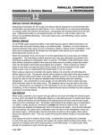
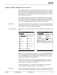

![[U1.04.00] Interface d`accès à Code_Aster : astk](http://vs1.manualzilla.com/store/data/006365830_1-acca3d2963d45973cab74b4dac5d0ed2-150x150.png)

![[U1.04.00] Interface d`accès à Code_Aster : astk](http://vs1.manualzilla.com/store/data/006381460_1-f9731cf2d4fb7a2d9200fd04c2516575-150x150.png)