1
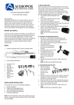
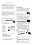
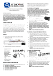
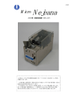
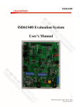
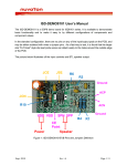
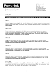
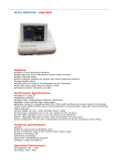
N3292x Development Board
User Manual
NHS-N3292x-1-PC-2M02
NHS-N3292x-1-PC-2D02
NHS-CMOS-1-PC-2D12
Ver:2.0
V2.00.000
Ver
1.0
1.1
2.0
Edit version
Description
Preliminary
Add USB2.0 Host/Device signal quality report
Update All circuit
V2.00.000
CONTENTS
1. N3292X DEVELOPMENT BOARD FUNCTION BLOCK: ........................................... 1 2. NHS‐N3292X‐1‐PC‐2M02 FUNCTION DESCRIPTION: ........................................... 2 2.1. 2.2. 2.3. FRONT VIEW: ............................................................................................................................................................ 2 BACK VIEW: .............................................................................................................................................................. 5 FRONT SIDE VIEW: ...................................................................................................................................................... 8 3. NHS‐N3292X‐1‐PC‐2D02 FUNCTION DESCRIPTION: .......................................... 10 3.1. FRONT VIEW: .......................................................................................................................................................... 10 4. NHS‐CMOS‐1‐PC‐2D12 FUNCTION DESCRIPTION: ............................................ 12 4.1. FRONT VIEW: .......................................................................................................................................................... 12 5. NHS‐N3292X‐1‐PC‐2M02 SCHEMATIC: ............................................................ 14 6. NHS‐N3292X‐1‐PC‐2D02 SCHEMATIC: ............................................................. 21 7. NHS‐CMOS‐1‐PC‐2D12 SCHEMATIC: ................................................................ 23 8. NHS‐N3292X‐1‐PC‐2M02 BOM LIST: ................................................................ 24 9. NHS‐N3292X‐1‐PC‐2D02 BOM LIST: ................................................................. 27 10. NHS‐CMOS‐1‐PC‐2D12 BOM LIST: ................................................................... 28 11. USB HOST 2.0 HIGH SPEED SIGNAL QUALITY REPORT: ..................................... 29 12. USB DEVICE 2.0 HIGH SPEED SIGNAL QUALITY REPORT: .................................. 30 13. FAQ: ............................................................................................................... 31 V2.00.000
1. N3292x Development Board Function Block: V2.00.000 Page 1
2. NHS‐N3292x‐1‐PC‐2M02 Function Description: 2.1. Front view: 2
○
1
○
5
○
4
○
3
○
6
○
7
○
8
○
9
○
10
○
11
○
14
○
13
○
12
○
15
○
21
○
19
○
20
○
17
○
16
○
22
○
23
○
18
○
V2.00.000 Page 2
1 Power Ready indicator:
○
Always lights on if system power ready.
2 The SDIC Plug-in indicator:
○
The SD card into the SDIC slot indicator will light on.
3 The SDIO Plug-in indicator:
○
The SD card into the SDIO slot indicator will light on.
4
○
Power Fail indicator:
If the external voltage is too high or over current indicator will light on.
5
○
Power Adopter jack:
Use 5V power adopter with 2.0mm head.
Fig1. Reference Polarity.
6 Cut off power adopter (CON11) switch:
○
+5V
CON11
0V
Fig1. Power adaptor input
Press the button key will cut off the power adopter source.
7 SDIC SD Card Slot:
○
Provide main chip SDIC function.
8
○
SDIO SD Card Slot:
Provide main chip SDIO function.
※ If you want to use SDIO must be confirmed whether the touch-panel
component removed.
9 ARM JTAG interface:
○
Software development and debug N3292x interface.
10 Debug port:
○
Most of the pin from main chip and provide debugging or developing.
11 NHS-N3292x-1-PC-2D02 connector:
○
Connected to the daughter board.
12 Nuvoton N3292x chip:
○
Main chip.
13
○
NAND Flash interface:
Provide 8 bit interface NAND type flash.
14 SPI Flash interface:
○
Provide 1/2/4 bit and SO-8/16 package type SPI flash.
※ If you want to use SPI0 must be confirmed whether the digital
microphone component removed.
15 CR1220 battery:
○
Provide 3V to W55F92 RTC.
16 RS-232 Interface:
○
Provide normal speed and high-speed interface.
V2.00.000 Page 3
17 Reset switch:
○
Press the button key will reset system.
18 System wake-up and power-down switch:
○
Press the button key will be through RTC wake-up and power-down
system power.
19 Communication interface:
○
Provide RJ-45 and an USB2.0 host interface.
20 USB Device interface:
○
Provide USB2.0 device interface.
21 Headphone interface:
○
Stereo headphone output and headphone detected function.
22
○
Speak interface:
Provide 1.5W power and can drive 8 or 4 ohm speakers.
23 Microphone interface:
○
4mm microphone.
V2.00.000 Page 4
2.2. Back view: 1
○
2
○
3
○
5
○
4
○
6
○
7
○
9
○
10
○
8
○
11
○
12
○
V2.00.000 Page 5
1 SDIO card detected function:
○
Enable/Disable card detected function (J23).
2 Power-on setting select:
○
Table as Fig. 2
3 NAND Flash PRE setting:
○
This will enable NAND flash PRE function if J19 is short.
※ NAND flash must provide this function, Otherwise no effect.
4 RS-232 normal and high speed functions select:
○
Table as Fig. 3
5 CMOS sensor2 or SDIO interface select:
○
J20 and J21 are used to select CMOS sensor2 or SDIO (SD1) interface.
6 .
※ If use the CMOS sensor2 interface must also set ○
6 EMAC or CMOS sensor2 interface select:
○
J6 - J15 are used to select EMAC(Ethernet) or CMOS sensor2 interface.
5 .
※ If use the CMOS sensor2 interface must also set ○
7 Power amplifier speaker enable:
○
This will enable ISD8101 power amplifier if J3 is short.
V2.00.000 Page 6
8 Power amplifier input source select:
○
(J4)Select Left or Right channel source to the power amplifier.
9 PHY interrupt interface enable:
○
It would interrupt to the CPU from the PHY, if J16 is short and PHY has
setting this function.
10 NHS-CMOS-1-PC-2D12 connector:
○
CMOS sensor2 interface connected to the daughter board.
11 Microphone Bias and Line-in select:
○
(J1)Select Microphone Bias or Line-in interface function.
12 USB Host bus power behavior select:
○
Table as Fig. 4.
※ If you choose 2-3, The SPI flash cannot work. But the bus power
can ON/OFF control from CPU.
V2.00.000 Page 7
2.3. Front side view: 1
○
2
○
3
○
11
○
V2.00.000 Page 8
1 RJ-45 Interface:
○
It provides a standard 10/100M interface.
PIN
1
2
3
4
SIGNAL
TX+
TXRX+
N.C
PIN
5
6
7
8
SIGNAL
N.C
RXN.C
N.C
2 Do not use:
○
Dummy.
3 USB Host interface:
○
It provides a standard USB2.0 interface.
PIN
1
2
SIGNAL
+5.0V
USB-
PIN
3
4
SIGNAL
USB+
GND
V2.00.000 Page 9
3. NHS‐N3292x‐1‐PC‐2D02 Function Description: 3.1. Front view: 2
○
3
○
1
○
4
○
6
○
5
○
V2.00.000 Page 10
1 LCD and Touch-Panel:
○
Provides an 8-bit interface LCD (GPM1006E0) and an touch-panel.
※ If you want to use touch-panel must be confirmed whether the SDIO
component removed.
2 Digital microphone:
○
Provide a digital microphone (AKU230).
※ If you want to use digital microphone must be confirmed whether
the SPI0 component removed.
3 NHS-CMOS-1-PC-2D12 connector:
○
CMOS sensor1 interface connected to the daughter board.
4 Low voltage detected emulation:
○
Providing a variable resistor to AHS pin, can simulate the behavior of
an external power.
5 Debug LED:
○
Provides 8 LED as debug or development (Active Low)
6 Analog key:
○
Provides 8 analog buttons key as development.
V2.00.000 Page 11
4. NHS‐CMOS‐1‐PC‐2D12 Function Description: 4.1. Front view: 1
○
2
○
V2.00.000 Page 12
1 CMOS sensor interface:
○
It provide 24pin CMOS sensor interface and pin outs are as follows.
2 CMOS sensor power down and reset function set:
○
You can use the J1 and J2 to set the pins can be controlled or use R1
and R4 fixed function.
V2.00.000 Page 13
5. NHS‐N3292x‐1‐PC‐2M02 schematic: V2.00.000 Page 1
V2.00.000 Page 15
V2.00.000 Page 16
V2.00.000 Page 17
V2.00.000 Page 18
V2.00.000 Page 19
V2.00.000 Page 20
6. NHS‐N3292x‐1‐PC‐2D02 schematic: V2.00.000 Page 21
V2.00.000 Page 22
7. NHS‐CMOS‐1‐PC‐2D12 schematic: V2.00.000 Page 23
8. NHS‐N3292x‐1‐PC‐2M02 BoM list: Item
1
2
3
4
5
6
7
8
9
10
Quantity
1
1
1
2
1
1
2
1
1
1
11
24
12
13
2
5
14
6
15
13
16
23
17
18
19
20
21
22
23
3
2
2
1
2
4
3
Reference
Part
Reference Link
BT1
CR1220
CON1
P35-157-P1Z9
CON2
USB-MINI-B
CON3,CON4
2.54mm-180D-32x2
CON5
2.00mm-180D-30X2
CON6
2.00mm-180D-12X2
CON7,CON8
Panasonic-Standard-SD
CON9
2.54MM-10x2
CON10
DSUB9
CON11
PowerJACK
C1,C5,C8,C9,C17,
C18,C35,C37,C39,
C40,C41,C43,C44,
10uF
C45,C58,C59,C61,
C67,C81,C87,C88,
C89,C90,C92
C2,C4
22uF
C3,C6,C7,C10,C11 300pF
C12,C13,C14,C15,
100pF
C19,C20
C16,C21,C22,C23,
C24,C25,C26,C46,
1uF
C55,C56,C66,C79,
C80
C27,C33,C34,C36,
C38,C62,C63,C64,
C65,C68,C70,C71,
0.1uF
C72,C73,C74,C75,
C76,C78,C82,C83,
C84,C85,C86
C28,C60,C91
100uF/6.3V
C29,C30
0.01uF
C31,C32
5pF
C42
0.1u
C47,C48
15pF
C49,C50,C51,C52 20pF
C53,C54,C57
10pF
V2.00.000 Page 24
24
25
26
27
28
29
30
31
1
1
1
1
1
2
1
1
32
10
33
34
35
36
3
1
1
2
37
6
38
18
39
12
40
4
41
42
43
44
1
1
1
3
45
7
46
13
47
48
49
50
2
1
2
2
C69
4.7uF
C77
47uF/6.3V
J17
2.00mm-4x2
J25
2.00mm-6x2-Jump
LED1
Blue-0603
LED2,LED3
Yellow-0603
LED4
Red-0603
LS1
HeadPhone-3
L1,L2,L3,L4,L5,L6,
FB
L7,L11,L12,L13
L8,L9,L10
2.2uH
M1
4mm-Microphone
Q1
2N9012
Q2,Q3
SI2301
RN1,RN4,RN9,
4.7K
RN10,R13,R15
RN2,RN3,R16,R38
,R39,R40,R41,R42
,R43,R49,R50,R51 10
,R52,R53,R54,R60
,R61,R62
RN5,RN6,RN7,R7,
RN8,R36,R46,R59, 10K
R77,R79,R80,R81
RN11,R25,R37,
33
R56
R1
8.2K
R2
1.6K
R3
5.6K
R4,R11,R57
5.1K
R5,R6,R12,R14,
82
R30,R45,R55
R8,R34,R35,R44,
R47,R48,R63,R70,
100K
R72,R74,R75,R76,
R82
R9,R23
390k
R10
91K
R17,R71
200K
R18,R22
2.2
http://www.bang-tec.com.tw
V2.00.000 Page 25
51
52
53
54
55
56
57
58
59
60
61
62
63
64
65
66
67
68
69
70
71
72
73
1
1
2
2
1
1
1
1
1
1
1
1
1
1
1
1
1
1
1
1
1
1
1
R19
R64
R65,R66
R67,R68
R69
R73
R78
S1,S2,S3
U1
U2
U3
U4
U5
U6
U8
U9
U10
U11
U12
U13
X1
X2
X3
2.49K-1%
10M
1M
12.1K
250
14K
45K
Bottom Key
ISD8101
APL3511A
RTL8201F-QFN-32
W55FA92DDN
HY27US08121A
W25QXXX-16
ICL-232E
APL3203
APW7176
APW7102
APL5537
HD74LV1G08A
32.768K
12MHz
25MHz
http://www.nuvoton.com
http://www.anpec.com.tw
http://www.realtek.com
http://www.nuvoton.com
http://www.hynix.com
http://www.winbond.com
http://www.anpec.com.tw
http://www.anpec.com.tw
http://www.anpec.com.tw
http://www.anpec.com.tw
V2.00.000 Page 26
9. NHS‐N3292x‐1‐PC‐2D02 BoM list: Item
1
2
3
4
Quantity
1
1
1
1
5
15
6
7
4
1
8
5
9
10
11
12
4
1
1
4
13
4
14
4
15
16
17
18
19
20
21
22
23
24
25
26
27
28
29
30
1
1
1
2
1
1
5
1
1
2
2
1
1
1
1
1
Reference
Part
CON1
GPM1006E0
CON2
2.00mm-180D-30X2
CON3
2.00mm-180D-12x2
CON4
2.54mm-180D-8x1
C1,C2,C3,C4,C5,
C6,C7,C8,C9,C15,C
1uF
16,C17,C18,C19,C2
0
C10,C11,C12,C13 300p
C14
2.2uF
C21,C23,C26,C27,C
0.1uF
31
C22,C24,C25,C28 10uF
C29
47uF/6.3V
C30
100uF/6.3V
D1,D2,D3,D4
RB521
LED1,LED2,LED3,
Green
LED4
LED5,LED6,LED7,
RED
LED8
L1
22uH
L2
FB
Q1
2N9013
RN1,RN2
82
R1
10
R2
4.7K
R3,R4,R5,R6,R7
15K-1%
R8
12K-1%
R9
20K-1%
R10,R15
10K
R11,R13
5.1K
R12
100K
R14
2.2
S1,S2,S3,S4,S5,S6 Bottom Key
U1
AKU230
U2
APW7136
Reference Link
http://www.mostyle.com
http://www.anpec.com.tw
V2.00.000 Page 27
10. NHS‐CMOS‐1‐PC‐2D12 BoM list: Item
1
2
3
4
5
6
10
11
12
13
Quantity
1
1
1
3
1
2
2
1
1
1
Reference
CON1
CON2
C1
C2,C3,C5
C4
C6,C7
R2,R3
R5
R6
U1
Part
FPC-24-0.5-CMOS
2.00mm-180D-12x2
100uF/6.3V
1uF
47uF/6.3V
0.1uF
1K
100K
220K
NTC3705U
Reference Link
V2.00.000 Page 28
11. USB HOST 2.0 High speed signal quality report: V2.00.000 Page 29
12. USB Device 2.0 High speed signal quality report: V2.00.000 Page 30
13. FAQ: Q1: If cannot turn-on the system power?
A1: Please check LED14 (Red LED) is lit.
If yes, the adaptor voltage is over 6.0V or system current is too high.
Q2: EMAC cannot work?
A2: Please check J6~J15 whether to switch to the RMII interface.
Q3: CMOS2 cannot work?
A3: Please check J6~J15 and J20~J21 whether to switch to the CMOS_2
interface.
Q4: SDIO cannot work?
A4: Please check J23 whether to short and touch panel whether to
disconnect.
Q5: Debug port no any signal (GPC8~15 and GPE0~1)?
A5: Please check J6~J15 whether to switch to the CMOS_2 interface.
Q6: Digital microphone cannot work?
A6: Please check J2-J3 (NHS-N3292x-1-PC-2D02) has short.
Q7: SPI Flash cannot work?
A7: Please check J5 has switch to (1-2)
V2.00.000 Page 31
Important Notice
Nuvoton products are not designed, intended, authorized or warranted for use as components in
systems or equipment intended for surgical implantation, atomic energy control instruments, airplane
or spaceship instruments, transportation instruments, traffic signal instruments, combustion control
instruments, or for other applications intended to support or sustain life. Furthermore, Nuvoton
products are not intended for applications wherein failure of Nuvoton products could result or lead to a
situation wherein personal injury, death or severe property or environmental damage could occur.
Nuvoton customers using or selling these products for use in such applications do so at their own risk
and agree to fully indemnify Nuvoton for any damages resulting from such improper use or sales.
V2.00.000 Page 32