Transcript
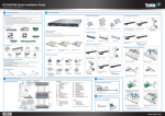
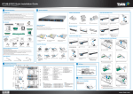
GN70-B7086 Quick Installation Guide
Document # D2318-100/ Revision 1.0
1
3
General Information
System Installation
Read Me First
Install 3.5” Hard Disk Drives
Install the Processor
1. The Barebone User’s Manual is available for download from our Web site at http://www.tyan.com. Make sure to read all
precautions and instructions before you start installing the server system.
2. Refer all servicing to qualified personnel to avoid the risk of damage to the server system.
3. Exercise normal ESD (Electrostatic Discharge) procedures during system integration. TYAN/MiTAC recommends wearing
gloves and an anti-static wrist strap to avoid possible damage to the equipment.
4. Current processor socket design places the pins on the motherboard instead of the processor itself. Exercise caution when
installing the processors as the manufacturer’s warranty does not cover damage inflicted upon the motherboard, including
damage to the CPU sockets.
Box Content
1 Open the socket lever.
2 Open the other
socket lever.
3 Open the CPU
4 Install the processor
socket cover.
and make sure the
goldend arrow is located
in the right direction
REMOVE
REMOVE
1
Press the locking lever latch and
pull the locking lever open.
2
Slide the HDD tray out.
4
Reinsert the HDD tray into the
chassis.
5
Press the locking lever to secure
the tray. Repeat the same
procedures to install other HDD
trays.
3
Place a hard disk drive into the
drive tray. Use 4 screws to secure
the HDD.
REMOVE
REMOVE
TYAN® S7086 system board
(pre-installed)
2U chassis, (8) hot swap HDD bays
(1+1) Redundant Power Supply,770W
DELTA DPS-770CB B80 plus (Gold)
5 Remove the CPU
Open the Chassis
(4) System fan
M1601T70-D-PDB Power
Distribution Board (pre-installed)
protective cap.
6 Close the CPU
socket cover.
7 Close the socket lever.
8 Close the other
socket lever.
Preparing the Chassis
HDD BP M1276G70-BP12E-8 /
M1276G70-BP12-8 (pre-installed)
Install the CPU Heatsink
Read normal ESD (Electrostatic Discharge) procedures.
Place your TYAN® Server Chassis on a flat anti-static surface to perform the following integration procedures. Read
ESD procedures before reaching inside to install components.
M1709G70-FPB
(pre-installed)
M7056-L24-3F Riser Card
(pre-installed)
M7056-R24-3F Riser Card
(pre-installed)
M1806G70-FB
(pre-installed)
Accessories
Installing the Add-On card (Optional)
FL00EUI-A
1 Remove the protective sheet.
(2) CPU heatsink
(1) Rail Kit
2 Install the CPU heatsink.
3 Secure the heatsink screws.
(1) DVD Bracket Kit
(3) Screw Pack
Install the Memory
1
Barebone Manual
(2) AC Power cord
125V (US)
(2) AC Power Cord
250V (EU)
(1) Barebone Manual
(1) TYAN® Motherboard
Drive CD
Loosen the 2
thumb screws on
the rear side and
remove the one
screw on the left.
2
Slide to release the
rear top cover and
then remove.
3
4
Remove the one
screw from the
front top cover.
Release the latches and
remove the front top
cover.
Remove the Air Duct
Required Hardware Components
Minimum Hardware Requirements
1 Unlock the clips.
To avoid integration difficulties and possible board damage, your system must meet the following minimum requirements:
• Processor: Intel® Xeon® processor E5-4600 product family (Sandy Bridge-EP 4S)
• Memory Type: Minimum of one 1GB, 240-pin DDR3 800/1066/1333-MHz DIMMs.
• Hard Disk Drives: 3.5" SATA/SAS HDD
• Rack Mount Kit (Industry 19" rack-mountable)
NOTE: The updated hardware requirements of the system please refer to the barebones user’s manual on our website at
www.tyan.com
2 Insert the memory module.
3 Lock the clips.
1 Remove the one screw on the PCI
2 Remove the PCI dummy bracket.
3 Connect the add-on card to
4 Secure the add-on card onto the
5 Carefully flip the riser 1 bracket and
6 Secure the 2 thumb screws
7 Remove the one screw on the the
8 Remove the PCI dummy bracket.
9 Connect the add-on card to the
10 Secure the add-on card onto the
11 Carefully flip the riser 2 bracket and
dummy bracket.
the riser 1 bracket.
Install the Air Duct
Tools Required
1
Phillips Screwdriver
Anti-Static Wrist Strap
Flat-head Screwdriver
2
Loosen the 3 thumb screws
and remove the one screw on
the riser bracket.
Lift the riser bracket out
of the chassis.
3
Release the air duct from the
guide pins and then remove
from the chassis.
1
Align the air duct to the guide pins
and install onto the chassis.
riser 1 bracket with the one screw.
Motherboard Placement
4
on the riser 1 bracket.
I/O Ports
32 31 30 29 28 27 26 25 24 23
Motherboard Placement
CPU1_DIMM_A0
CPU1_DIMM_A1
CPU1_DIMM_B0
CPU1_DIMM_B1
1
2
3
CONNECTORS
N
M
22
21
REMOVE
4
5
6
7
1.
2.
Intel
Wellsburg
PCH
CPU 1
Intel i350
8
b c
a
REMOVE
A
9
10
d
11
B
D
C
E
e
CPU1_DIMM_D1
CPU1_DIMM_D0
CPU1_DIMM_C1
CPU1_DIMM_C0
L
CPU0_DIMM_A0
CPU0_DIMM_A1
CPU0_DIMM_B0
CPU0_DIMM_B1
J
K
I
20
19
REMOVE
2
insert onto the chassis.
Battery
BIOS
12
CPU 0
AST2400
REMOVE
18
13
CPU0_DIMM_D1
CPU0_DIMM_D0
CPU0_DIMM_C1
CPU0_DIMM_C0
gf
14
F
15
16
17
H
G
3.
4.
5.
6.
7.
8.
9.
10.
11.
12.
13.
14.
15.
LAN Port # 2 Connector
Vertical Type SATA 3.0 Connector
(SATA5, up, SATA4, down)
VGA Port/COM Port
System Fan 4 Connector
ID button
Clear button
LAN Port # 1 Connector
LAN Port # 2 Connector
ID LED Button
System Fan 5 Connector
TYAN Module Header
BMC LED
COM 2 Port
Fan I/O Header
Front Panel Header/LAN Port # 2
Header
IPMB Connector
System Fan 0 Connector
Power Connector
System Fan 3 Connector
System Fan 2 Connector
System Fan 1 Connector
Power Connector
PCIE Header
System Fan 1 Connector
USB 2.0 Header
PSMI Connector
Power Connector
USB 3.0 Header
Type A USB Header
4-in-1 Mini SAS Connector (SATA0-3)
PCH SATA SGPIO Header
4-in-1 Mini SAS Connector (SATA0-3)
Locate the External I/O Port
LAN Port #3
(IPMI)
LAN Port #1
(LAN1)
LAN Port #2
(LAN2)
(2) USB 3.0
VGA Port
5
COM1 Port
ID LED Button
PCI dummy bracket.
riser 2 bracket.
Caution
JUMPER
SLOTS
A
B
C
D
E
F
G/H/I/J
K/L/M/N
16.
17.
18.
19.
20.
21.
22.
23.
24.
25.
26.
27.
28.
29.
30.
31.
32.
PCI-E Gen3 x8 Mezzanine card slot (CPU0)
PCI-E Gen3 x16 Riser card slot (CPU1)
PCI-E Gen3 x16 Riser card slot (CPU0)
PCI-E Gen3 x4 Riser card slot (CPU1)
PCI-E Gen3 x4 Riser card slot (CPU0)
PCI-E Gen3 x8 Mezzanine card slot (CPU0)
CPU0 DIMM Slots
CPU1 DIMM Slots
a
b
c
d
e
f
g
PSU Alert Disable Jumper
BIOS Security Jumper
ME Recovery Mode Jumper
Buzzer Disable Jumper
MIC Card Jumper
ID LED Button Header
Chassis Intrusion Header
NOTE: There is risk when setting the jumper by yourself.
CPU Cover for DOA/RMA
NOTE: Please save and replace
the CPU protection cap
when returning the server
board for service.
riser 2 bracket with the one screw.
insert onto the chassis.
NOTE: Connect the add-on power cable to the connector of the add-on module.
12 Secure the one thumb screw and
the one screw on the
riser 2 bracket.