Transcript
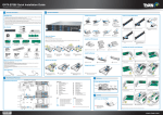
S7053 Quick Installation guide
Document # D2186-100/ Revision 1.0
Read Me First
1. The motherboard User’s Manual is available for download from our Web site at http://www.tyan.com. Make sure to read all
precautions and instructions before you start installing the server board.
2. Refer all servicing to qualified personnel to avoid the risk of damage to the server board.
1
Install the Server Board
1 Insert the server board into the chassis.
2
Attach the server board to the chassis by securing
the screws on the designated locations.
3. Exercise normal ESD (Electrostatic Discharge) procedures during system integration. TYAN/MiTAC recommends wearing
gloves and an anti-static wrist strap to avoid possible damage to the equipment.
CPU 1
CPU 1
4. Current processor socket design places the pins on the motherboard instead of the processor itself. Exercise extreme
caution when installing the processors as the manufacturer’s warranty does not cover damage inflicted upon the motherboard, including damage to the CPU sockets.
CPU 0
CPU 0
Note: To avoid damage,
do not use torque force
greater than 7kgf/cm
(6.09 lb/n) on each screw.
Package contents
2
Quick Installation
Guide
CPU 1
CPU 0
SATA Cable x 6
Server Board x 1
Rear I/O Shield x 1
Driver's and Utilities CD x 1
Install the processoer
Quick Installation Guide x 1
Tools prepared
1 Remove the CPU
protective cap
Phillips Screwdriver
Flat-head Screwdriver
the
2 Open
socket levers
the
3 Open
socket levers
the CPU
6 Close
Socket Cover
the
7 Close
socket levers
the CPU
4 Open
Socket Cover
Anti-Static Wrist Strap
Motherboard Placement
33
32
31
Install the processor
1
30
C
2
make sure the
5 and
gold arrow is located in
the right direction
3
A
8
Install the CPU Heatsink
3
Apply the thermal
4
29
CPU 1
5
6
CPU 0
2
3
25
f
11
h
j
6
12
a
i
13
14
15
16
18
cb
19 20 21
SLOTS
A
B
C
D
CPU0 DIMM SLOT [Channel A/B]
CPU0 DIMM SLOT [Channel C/D]
CPU1 DIMM SLOT [Channel G/H]
CPU1 DIMM SLOT [Channel E/ F]
1
2
3
4
5
6
PCIE slot (x8) from CPU1
PCIE slot (x8) from CPU0
PCIE slot (x16) from CPU1
PCIE slot (x8) from CPU0
PCIE slot (x16) from CPU1
PCIE slot (x8) from CPU0
ID_LED Button (SW1)
VGA Port and COM1 Port
LAN port #4(LAN4) and USB2.0 ports
LAN port #3(LAN3) and USB2.0 ports
LAN port#2 (LAN2) and LAN port#1(LAN1) share with IPMI port
CPU1_FAN
SYS_FAN4
SYS_FAN5
ID_LED
AST2300 chipset
COM2 Header(J3)
4-pin Power Connector(PW4)
IPMB Pin Header
System Fan Header
Clear Button
4 in 1 Mini SAS connector (J27)
4 in 1 Mini SAS connector (J25)
TYPE-A USB From PCH
4in1 SAS connector (for SATA function)
Front USB Header
Front USB Header
Front Panel Header
SGPIO Connector
SATA0~5
(SATA0~1——SATA3.0)
(SATA2~5——SATA2.0)
SYS_FAN3
BIOS
8-pin Power Connector(PW2)
CPU0_FAN
SYS_FAN2
SYS_FAN1
24-pin Power Connector(PW1)
PSMI Connector
8-pin Power Connector(PW3)
With jumper installed
on pins 1 and 2
Jumper
Top View
2
3
1 Unlock the clips.
2 Insert the memory module.
3 Lock the clips.
23
5
Install the Power Cable
HEADER
Name
a
b
c
d
e
CPU 1
Discription
INTRUDER header
LAN Port3 Pin Header
LAN Port4 Pin Header
ID LED Pin Header
BMC RST header
CPU 0
JUMPER
Name
f
g/h
i
j
Discription
ME RECOVERY MODE Jump
COM Select
SAS Enable/Disable Jump
Flash Descriptor Security
Override MODE Jump
Locate the external I/O port
Ethernet
(LAN1~LAN4)
DOA/RMA Reminder
Without jumper
Install the memory
22
1.
2.
3.
4
5
6.
7
8
9
10
11
12
13
14
15
16
17
18
19
20
21
22
23
24
Jumper Cap On/Off
1
17
CONNECTORS
25
26
27
28
29
30
31
32
33
4
24
5
ge
heatsink fan cable.
26
4
d
4 Connect the
B
1
10
3 Secure the heatsink screws.
27
D
9
2 Install the CPU heatsink.
28
7
8
1 grease.
VGA
Note: Please save and replace the CPU
protection cap when returning the server board
for service.
Top View
Pins
1
2
3
ID LED button (SW1)
www.tyan.com
COM1
USB 2.0
USB 2.0
share with IPMI
ID_LED
5 6 1 8 T4 6 3 0 0 0 2