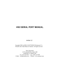
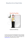
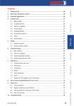
1
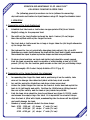
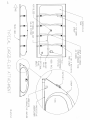
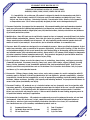
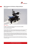
FLEX-TANKS ™
®
OPERATION AND MAINTENANCE OF:
“ATL” CARGO-FLEX
™
COLLAPSIBLE TRANSPORT BLADDER TANKS
ACCESS FLANGE
(FILL/DISCHARGE)
LOOP
HANDLES
AIR BLEED
CARGO-FLEX ™
RATCHET
TIE- DOWN
FINAL
DRAIN
UNDER LINER
AERO TEC LABORATORIES INC. • U.S.A.
RAMSEY, NEW JERSEY 07446-1251
TEL: 201-825-1400
FAX: 201-825-1962
e-Mail: [email protected]
AERO TEC LABORATORIES LTD. • U.K.
MILTON KEYNES, ENGLAND MK13-8PU
TEL: 0-1908-351700
FAX: 0-1908-351750
e-Mail: [email protected]
D
S
6/ -54
03 7
www.pillowtanks.com
OPERATION AND MAINTENANCE OF ATL CARGO-FLEX™
COLLAPSIBLE TRANSPORT BLADDER TANKS
The following general procedures are to be followed in converting
dry-bed trucks and trailers to liquid tankers using ATL Cargo-Flex bladder tanks:
I. OPERATION
A. Preparation of the truck/trailer bed:
1.
Establish that the truck or trailer has an appropriate GVW (Gross Vehicle
Weight) rating for the proposed load.
2.
The width of the truck/trailer bed must be least 6 inches (15 cm) larger
than the unfilled width of the Cargo-Flex tank.
3.
The truck bed or trailer must be as long or longer than the flat length dimension
of the Cargo-Flex tank.
4.
The bed must be free of potentially damaging sharp objects. Use of an ATL
Underliner or canvas sheet between the tank and the truck bed is highly recommended.
These should be taped in place before the straps and tank are positioned.
5.
Tie-down strap locations on truck and trailer beds should be evenly spaced.
Each tie-down connection must be capable of withstanding a load of 20,000
pounds (89 kn). Use the location guide arrows on the tank for positioning straps.
6.
Read thoroughly ATL Product Safety Bulletin #DS 370 (pg. 8)
B. Preparation of the Cargo-Flex tank (See diagrams):
1.
In unpacking the Cargo-Flex tank and in positioning it on the vehicle, take
care not to damage the rubberized fabric with sharp tools or nails.
2.
Lay out the protective Underliner and drape straps across bed.
3.
Center the folded Cargo-Flex tank on the truck or trailer bed and unfold the
tank to its full length and width. Position the fill/discharge fitting toward
the rear of the vehicle, and the tank as far forward as possible.
4.
Each tie-down strap should be loosely positioned per figure 10-2121A, under
and around the empty Cargo-Flex tank. It is important to orient all straps.
Once the tank is filled with liquid, manhandling the tie-downs will be difficult
and could damage the tank.
5.
Number of evenly spaced ratchet tie-down straps:
Tank 1000 - 1200 gal.
(2) straps
3” wide (7.6 cm)
1500 - 4600 gal.
(4) straps 3” wide (7.6 cm)
5000 - 6000 gal.
(6) straps 3” wide (7.6 cm)
2
3.
4.
5.
6.
7.
C. Attachment of Fittings:
1. Optional fill/discharge components such as the 2-inch (50 mm) elbow, 2-inch quickcoupler adapter, and 2-inch valve (if ordered) are packed with the tank, but unassembled.
4-inch NPT valve assemblies are also available for 3000 to 6000 gal. Cargo-Flex Tanks.
2.
Remove the “obround” access cover plate. Attach the NPT elbow to the NPT gate valve
and quick coupler. Tighten this assembly into the mating threaded boss. Be sure that
the elbow is facing the direction desired for connection of your fill/discharge hose.
(See diagram #10-2124A).
Reattach the cover plate and gasket to the tank access opening and torque the bolts to
40 in. lb. (4.5 NM). Avoid tightening or re-positioning of the elbow in the cover plate while the
cover plate is fastened to the tank, to avoid potential tank damage.
If supplied, attach the pressure relief valve system (See diagram #10-2121A) to the 1-inch
(25mm) or 2-inch (50mm) air bleed fitting on the top center of the tank.
Fasten one end of your fill/discharge hose to the quick-coupler adapter on the 2-inch or
4-inch valve and the other end of the hose to your filling pump.
All connections must be properly seated and sealed with thread compound to prevent leaks.
Read and apply the provisions of ATL Product Safety Bulletin #DS 370 before proceeding.
D. Filling of tank:
1.
2.
3.
4.
5.
6.
7.
8.
9.
10.
11.
12.
13.
The truck or trailer bed must be on a level site when the tank is being filled to avoid tank “rolling”.
Open the 1-inch relief valve and walk with soft-soled shoes on the flat tank to expel as much
air as possible.
Close the relief valve and, if your Cargo-Flex tank has another vent or bottom-drain fitting,
ensure that these are closed and sealed before you begin filling.
Connect your fluid source to the 2-inch or 4-inch fill/discharge valve with a hose assembly
(see diagram 10-2124A).
Open that valve and begin to fill the tank by gravity or pumping. 100 gpm (400 liters per
minute) is a proper fill rate. Should start slowly to avoid “whipping”.
If the Cargo-Flex tank starts to shift or roll, discharge the liquid and level the truck bed.
Fill the tank to a height of forty-four (44) inches (112 cm), for tanks of 1,000 to 6,000 gal.
(4,000 to 24,000 liter) capacity.
Keep the tie-down straps aligned as well as possible.
Pull the straps manually through the ratchets to remove all slack.
Engage each ratchet handle to its gear and tighten the straps slightly (one or two strokes of
the handle). Make sure the ratchets are engaged and locked to prevent the straps from loosening.
If provided, open the relief valve slightly and fill the tank further until that valve just starts
to allow discharge. Adjust the ratchets if necessary and close the relief valve. For tanks
equipped with a pressure gauge, an internal pressure of 2 to 4 psi (0.2 Bar) is desirable for
stability.
Close the 2-inch or 4-inch fill valve and disconnect the filling hose. Secure that hose some
where else on the vehicle.
If, for any reason, the straps become loose after the tank is filled, retighten
them with the ratchets. Should all the "take-up" capacity of any ratchet be used
up, disengage the ratchet and manually pull the strap’s free-end to remove
all the slack. The ratchet can then be engaged, and it will be able to tighten
the strap further.
4
E. Emptying of Tank:
Emptying the Cargo-Flex tank should be done on a level site or slightly inclined
to position the fill/discharge port at a lower elevation. Fluid is normally withdrawn
through the fill/discharge fitting, or it may be drawn by gravity from the bottom
drain fitting if provided.
1.
2.
3.
4.
Attach a fill/discharge hose to the tank and receiver vessel or pump.
Open the 2-inch or 4-inch valve to begin discharge by gravity or pump.
The tank may be rolled up from front to rear to force liquid toward the outlet or toward
the “final drain” corner port if provided.
After the tank is empty and the tie-down straps are loose, remove and store these straps
with their ratchets away from the tank to prevent abrasion.
F. Folding and Storage of Tank:
1.
2.
3.
Cargo-Flex tanks may be rolled or folded for temporary storage. Care must be taken to
protect protruding fittings from damage or from causing abrasion to the tank body.
If the tank is to be stored for a period of several months, it is recommended that it be
cleaned inside and out. ( See User Manual # DS-361)
The tank should be stored in a cool, dry area and be protected from exposure to direct
sunlight and moisture. Underliner may be folded or rolled for storage.
G. Cleaning of Tank*:
1.
2.
3.
4.
The Cargo-Flex interior may be cleaned using soft detergents or low temperature wet steam.
Water tanks should be cleaned with wet steam only.
Do not use hot clear steam as it may damage the elastomer. max. 220˚ F, 105˚C
When cleaning with warm water detergents, the tank may be filled to 1” (25mm) depth and
walked on. This will agitate the cleaning liquid and wet all surfaces (See User Manual #DS-361).
Discharge and rinse through the “obround” access flange or "final drain".
* Caution —- Sludge deposits and residuals in a tank may give off toxic or explosive vapors.
Adequate ventilation must be provided to remove fumes.
II. MAINTENANCE
A. Inspection and Care:
1.
2.
3.
4.
The outside of your Cargo-Flex tank should be periodically cleaned with a mild soap solution.
All fittings should be clean and free of corrosion with seals tight to prevent leaks.
Tie-down straps and tank surfaces should be free of nicks, cuts and abrasion.
Any damaged areas should be repaired immediately. (See User Manual # DS-361)
B. Temporary Repairs:
1.
2.
3.
In case of damage to a filled Cargo-Flex tank it is recommended:
a. that temporary repair clamps be readily available and kept with the tank at all times.
b. that the operator of the tank be trained in the use of the temporary repair clamps.
The temporary repair kit clamps are 5” clam-shell type. Usually the Cargo-Flex
will need to be offloaded before the clamp can be applied.
Temporary repair clamps are available from Aero Tec Laboratories Inc.,
Ramsey, NJ USA, but should only be used in an emergency.
6
C. Temporary Repair Procedure:
1.
2.
3.
Slit the tear carefully and slightly to accommodate the clamp.
Remove the clamp's top plate, fold the hinged stud down, and push the smaller
plate through the tear.
With the oval plate inside of tank, straighten the stud, rotate the plate 90°,
slide the outer plate over the stud and screw the wing-nut down snugly.
( See User Manual # DS-361)
D. Permanent Repairs:
1.
2.
3.
It is necessary that permanent type repairs be done as soon as possible by a qualified technician.
It is recommended that the tank be cleaned and returned to an ATL Plant for repairs.
For other repairs, it is recommended that the work be done by a qualified technician who
is familiar with the Cargo-Flex repair procedures. The tank owner can obtain a permanent
repair kit from ATL by supplying the tank serial number or part number.
E. Permanent Type Repair Procedure (See User Manual DS-361):
1.
2.
3.
4.
5.
6.
7.
8.
9.
10.
11.
12.
13.
14.
15.
Drain , empty and clean the tank completely.
Perform the repair work at room temperature and less than 50% relative humidity
conditions. Use only approved Cargo-Flex repair kits from ATL.
Position the tank so that the inside of the tear is opposite and accessible through the
obround access flange opening.
Scrub, rinse and dry all surface dirt for six inches around the tear by using a stiff brush.
Thoroughly roughen the interior surface of the tank for a distance of 6 inches around the
tear. Use the emory cloth provided.
Remove all the liquid that has soaked into the rubber around the wound by washing the
interior surface with solvent. Repeat if necessary. Allow the area to dry for an hour, and
re-scrub the interior roughened surface with soap and water and allow it to dry. The soap
should be thoroughly rinsed off and the area rewashed with solvent.
Cut a patch from the provided material to overlap the tear by 3 inches on all sides but to
be smaller than the roughened area on the inner tank wall.
Roughen one side of the patch completely and wash it with solvent. Allow it to dry for 45
minutes.
Thoroughly brush one coat of adhesive cement on the buffed surfaces of the inner tank wall
and the repair patch. Allow the first coat to dry, generally 45 minutes.
Apply a second coat of cement to both surfaces and allow it to dry to tack (about 15
minutes). If the cement overdries, liven it with a swab moistened with the solvent supplied.
Apply the cemented surface of the patch to the cemented surface of the tank interior.
Using the roller, push vigorously, but uniformly, from the center of the patch to the outside
so as to remove trapped air.
Apply pressure for 8 hours on the repair area using a C-clamp and wooden/metal plates with
a pad of poly film between the plates and the tank.
Reposition the tank to expose the exterior (tank outside) of the tear and repeat steps 4
through 13 using another repair patch cut from provided material.
Allow 24 hours of air cure time before putting the tank into service.
*Note: Repair kits vary according to tank type and service. Specific repair
instructions may also vary slightly from those above. Follow the individual kit
procedure whenever possible.
7
ATL PRODUCT SAFETY BULLETIN #DS-370
IMPORTANT PRECAUTIONS IN USING ATL FLEXIBLE TANKS,
BLADDERS, DRUMS, PLUGS, VALVES, LINERS AND AIR CELLS
1.) Compatibility: Be certain your ATL product is designed to handle the temperature and fluid in
question. When in doubt, contact ATL to discuss specific model numbers and material types. Never
subject any item to Ketones, Chlorinated Solvents, Concentrated Acids, Alkalies, Pure Aromatics
or temperatures over 140∞F unless specifically designed for that service and approved by ATL.
2.) Personnel Protection: Be prepared for the unexpected. All personnel handling fuels and hazardous chemicals
must wear full protective clothing and equipment of an impervious, non-static and flame-resistant type.
Specific information should be sought from your fuel/chemical vendors, industry associations and producers
of personnel protection systems.
3.) Multiple Uses: Some ATL tanks can be sufficiently cleaned to store or transport several different, but similar,
liquids without contamination. However, never take this factor for granted. Field and laboratory testing are
always required before suitability can be assured. ATL can frequently provide material samples and scale
models to assist in your analysis. Never switch a fuel or chemical container to a comestibles use.
4.) Pressure: Most ATL products are designed for use at ambient pressure. Unless specifically designated, Do Not
subject any container, valve or connection to pressure differential. Do Not restrict venting; Do Not overfill or
exceed maximum height; Do Not exceed normal flow rates during filling or discharging; and Do Not pressurize
any inflatable unless fully restrained and enclosed. Always allow a 10% volume factor (ullage) to compensate
for vapor expansion, thermal expansion and overfill. Those products designed for pressurization should be
fully contained or restrained in a rigid structure before filling.
5.) Fire & Explosion: Always exercise the utmost care in containing, transferring, venting or processing
flammable materials. Keep away from fire, flame, heat, spark, static charge, oxygen, lightning, focusing
lenses, friction, turbulence or any combustible materials that could spontaneously ignite. Refer to your
industry specialists and publications such as The National Fire Prevention Association Code for proper
avoidance of fire and explosion hazards.
6.) Accessories: Fittings, flanges, piping, hoses, valves, vents, meters, pumps etc. used in conjunction with ATL
products must be designed, selected and maintained for leak-tightness, galvanic compatibility, chemical
compatibility, thread and seal compatibility, as well as appropriate grounding, electrical bonding, vibration
tolerance, tamper-resistance, flexibility, flow capacity and mounting methods. Get professional assistance to
assure total system functionality and safety.
7.) Personnel Training: ATL products are of a technical nature and are frequently used in conjunction with
hazardous materials. All operating and support personnel must be trained in the user’s specific application
of these ATL items. A full familiarity with the important safety precautions and procedures is essential
before any such devices are placed in service. Each user must establish his own training program geared to
his particular industry and specific application.
8.) Environmental Considerations: ATL products are engineered so as not to endanger the water, air and land
environments. Many ATL devices are, in fact, employed specifically for pollution abatement purposes.
Nevertheless, wherever fuels and potentially hazardous substances are stored, ATL recommends
the simultaneous use of its secondary containment products such as:
1.)
2.)
3.)
Permanent Berm Liners
Inflatable Berm and Liner Systems
Pit and Pond Liners
4.)
5.)
6.)
Tank “Envelopes”
Portable Dikes
2-ply Flex Tanks
8
9.) Weathering: Undue exposure to the natural elements may adversely affect ATL
products. Minimize exposure to sunlight (ultraviolet), ozone, severe hail, ice loading,
freeze-thaw cycling, water immersion and extremes of temperature. ATL offers these
protective accessories to help guard against adverse weathering effects:
1.)
Sun-Shield Covers
3.)
Metal Container
2.)
Ground Cloths & Geotextiles
4.)
Fire-Shield Covers
This equipment, in conjunction with reasonable care and maintenance, will significantly improve the retention
of physical properties and hence product longevity.
10.) Flex Fatigue:
Like most materials, the polymers, laminates and flexible composites used in most ATL
products can weaken from severe pinching, creasing, folding, and flex-cycling. Normal collapsing and
extending produce no ill effects, but compaction, inversion and crushing will decrease physical properties.
Some materials comprised of high performance filaments are especially susceptible to flex-fatigue and require
diligent care to avoid abuse during packing, operating, storing and unfolding.
11.) Set Up and Installation: ATL provides User Manuals and/or installation instructions for most standard
products. However, specialty items and custom made products require the user to formulate his own
procedures or draw on established standards such as ASTM, ASME, SAE, ISO etc.
12.) Cleaning and Storing: All products should be periodically cleaned, especially if they are to be stored for
extended periods. Follow the User Manual procedures or contact ATL for assistance.
13.) Leak Testing: Prior to use, all tank and container type products should be leak tested. This procedure can
generally be done with 1/8 psi air pressure and a standard bubble-type leak detector solution. Follow the
User Manual procedure or contact ATL for help. Always rinse and dry the surface after testing.
14.) Intended Purpose: Never use an ATL product for an application other than that intended unless specifically
authorized. For example, don’t use a static storage tank for dynamic operations, don’t use an air inflatable
to contain nitric acid or a berm liner as a field cover. Be methodical; order precisely what you need, and avoid
“adaptations”.
15.) Abrasion: Plastics, rubber and fabrics can deteriorate from excessive abrasion or chafing. ATL’s compounds
minimize this wearing effect, but all efforts should be made to avoid dragging, rubbing, cutting and scuffing
of flexible materials. Poly slip-sheets, talc, light oil and “doubler” patches frequently help ward off abrasion,
but the best protection is reasonable care in handling and use.
16.) Repairs: All repairs to ATL products should be performed at the factory. When this is not practicable, and
where field repairs are authorized, a reasonably skilled technician can patch and seal most ATL flexible
containers. Be certain to use only the appropriate ATL repair kit, and perform the repair in a clean, wellequipped facility, following the repair instructions precisely. Remember, not all damage is repairable.
Do Not attempt to repair a tank, drum, air cell etc. that has been broadly weakened by chemical attack,
ozone effect, UV exposure etc.
17.) When in Doubt:
Do Not take chances. Please contact ATL for assistance. We can help either
directly or by referral to a source of safety information for your particular problem.
Here are 6 ways to reach ATL for technical help:
9
Notes:
www.pillowtanks.com
AERO TEC LABORATORIES INC. • U.S.A.
RAMSEY, NEW JERSEY 07446-1251
TEL: 201-825-1400
FAX: 201-825-1962
e-Mail: [email protected]
AERO TEC LABORATORIES LTD. • U.K.
MILTON KEYNES, ENGLAND MK13-8PU
TEL: 0-1908-351700
FAX: 0-1908-351750
e-Mail: [email protected]
10