1
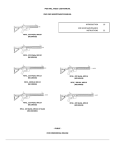
4I63 SERIAL PORT MANUAL
version 1.2
Copyright 2005 by MESA ELECTRONICS Richmond, CA.
Printed in the United States of America. All rights reserved.
Mesa Electronics
4175 Lakeside Drive, Suite #100
Richmond, CA 94806-1950
Tel (510) 223-9272 - Fax (510) 223-9585
E-Mail: [email protected] - Website: www.mesanet.com
4I63 USER'S MANUAL
4I63 USER'S MANUAL
TABLE OF CONTENTS
HANDLING PRECAUTIONS
Static electricity . . . . . . . . . . . . . . . . . . . . . . . . . . . . . . . . . . . . . . . . . . . . . . . . . . . . . . . . . . . . . . . . . . . . . . . 4
INTRODUCTION
General . . . . . . . . . . . . . . . . . . . . . . . . . . . . . . . . . . . . . . . . . . . . . . . . . . . . . . . . . . . . . . . . . . . . . . . . . . . . . . . . 5
CONFIGURATION
General . . . . . . . . . . . . . . . . . . . . . . . . . . . . . . . . . . . . . . . . . . . . . . . . . . . . . . . . . . . . . . . . . . . . . . . . . . . . . . . . 6
Default jumper settings . . . . . . . . . . . . . . . . . . . . . . . . . . . . . . . . . . . . . . . . . . . . . . . . . . . . . . . . . . . . . . . . 6
Card versions . . . . . . . . . . . . . . . . . . . . . . . . . . . . . . . . . . . . . . . . . . . . . . . . . . . . . . . . . . . . . . . . . . . . . . . . . . 6
Serial PCI Slot Select . . . . . . . . . . . . . . . . . . . . . . . . . . . . . . . . . . . . . . . . . . . . . . . . . . . . . . . . . . . . . . . . . . 8
Printer PCI interrupt select . . . . . . . . . . . . . . . . . . . . . . . . . . . . . . . . . . . . . . . . . . . . . . . . . . . . . . . . . . . . 8
8X baud rate option . . . . . . . . . . . . . . . . . . . . . . . . . . . . . . . . . . . . . . . . . . . . . . . . . . . . . . . . . . . . . . . . . . . . 8
RS-422 driver enable . . . . . . . . . . . . . . . . . . . . . . . . . . . . . . . . . . . . . . . . . . . . . . . . . . . . . . . . . . . . . . . . . 10
RS-422/RS-485 half duplex enable . . . . . . . . . . . . . . . . . . . . . . . . . . . . . . . . . . . . . . . . . . . . . . . . . . . 10
INSTALLATION
General . . . . . . . . . . . . . . . . . . . . . . . . . . . . . . . . . . . . . . . . . . . . . . . . . . . . . . . . . . . . . . . . . . . . . . . . . . . . . . . 13
CONNECTOR PINOUTS
Serial connector pin-out . . . . . . . . . . . . . . . . . . . . . . . . . . . . . . . . . . . . . . . . . . . . . . . . . . . . . . . . . . . . . . 14
Printer connector pin-out . . . . . . . . . . . . . . . . . . . . . . . . . . . . . . . . . . . . . . . . . . . . . . . . . . . . . . . . . . . . . 18
Misc I/O connector pin-out . . . . . . . . . . . . . . . . . . . . . . . . . . . . . . . . . . . . . . . . . . . . . . . . . . . . . . . . . . . 19
OPERATION
OXPCI954 UART operation . . . . . . . . . . . . . . . . . . . . . . . . . . . . . . . . . . . . . . . . . . . . . . . . . . . . . . . . . 20
Supplied drivers . . . . . . . . . . . . . . . . . . . . . . . . . . . . . . . . . . . . . . . . . . . . . . . . . . . . . . . . . . . . . . . . . . . . . . 20
RS-422/RS-485 unused signals . . . . . . . . . . . . . . . . . . . . . . . . . . . . . . . . . . . . . . . . . . . . . . . . . . . . . . . 20
RS-485 operation . . . . . . . . . . . . . . . . . . . . . . . . . . . . . . . . . . . . . . . . . . . . . . . . . . . . . . . . . . . . . . . . . . . . . 20
RS-422/RS-485 driver enable . . . . . . . . . . . . . . . . . . . . . . . . . . . . . . . . . . . . . . . . . . . . . . . . . . . . . . . . 20
REFERENCE INFORMATION
Specifications . . . . . . . . . . . . . . . . . . . . . . . . . . . . . . . . . . . . . . . . . . . . . . . . . . . . . . . . . . . . . . . . . . . . . . . . 21
Warranty . . . . . . . . . . . . . . . . . . . . . . . . . . . . . . . . . . . . . . . . . . . . . . . . . . . . . . . . . . . . . . . . . . . . . . . . . . . . . 22
Schematic diagrams . . . . . . . . . . . . . . . . . . . . . . . . . . . . . . . . . . . . . . . . . . . . . . . . . . . . . . . . . . . . . . . . . . 23
4I63 USER'S MANUAL
HANDLING PRECAUTIONS
STATIC ELECTRICITY
The CMOS integrated circuits on the 4I63 can be damaged by exposure to electrostatic
discharges. The following precautions should be taken when handling the 4I63 to prevent
possible damage.
A. Leave the 4I63 in its antistatic bag until needed.
B. All work should be performed at an antistatic workstation.
C. Ground equipment into which 4I63 will be installed.
D. Ground handling personnel with conductive bracelet through 1 megohm resistor to
ground.
E. Avoid wearing synthetic fabrics, particularly Nylon.
Page 4
4I63 USER'S MANUAL
INTRODUCTION
GENERAL
The 4I63 is a COMX compatible, four channel serial + printer port card implemented on a
stackable PC/104-Plus bus card. The 4I63 is available in three versions: quad RS-232, a model with
two RS-232 and two RS-422 channels, and quad RS-422. The model names of the cards are
(respectively) 4I63A, 4I63B, and 4I63C
The 4I63 uses Oxford Semiconductor Quad PCI UARTS with 128 byte receive and transmit
FIFOs The UART's 128 byte receive and transmit FIFO's plus the lower overhead of the PCI bus
allow higher baud rates or more channels than PC/104 serial cards.
The RS-422 drivers can be software and hardware controlled for bus (RS-485) type
applications. Jumper selectable RS-422 termination is provided on card. A jumper selectable 8X
baud rate option allows RS-422 channels to run at up to 921K baud. When combined with the
software enabled 4X oversampling mode, Baud rates of up to 3.686M baud are possible,
Serial port connector is a 40 pin latching type header. The cable from this header can be
terminated in 4 male IDC DE9 connectors. These connectors will have the standard AT type RS-232
serial port pinout. RS-422 pinout is similar to the RS-449 secondary channel pinout.
The 4I63 requires only +5V for operation, as all RS-232 power is generated on card. All CMOS
technology keeps power dissipation to a minimum.
Page 5
4I63 USER'S MANUAL
CONFIGURATION
GENERAL
The 4I63 has a number of jumper configurable options that must be properly set to match the
application. Each group of jumpers will be discussed separately by function. In the following
discussions, when the words "up", "down", "right", and "left" are used it is assumed that the 4I63
serial I/O card is oriented with its bus connectors J1 and J2 at the bottom edge of the card (nearest the
person doing the configuration).
The four serial channels are referred to as channel 0, channel 1, channel 2, and channel 3.
DEFAULT JUMPER SETTINGS
Factory default 4I63 jumpering is as follows:
FUNCTION
JUMPER(S)
SETTING
Ch 0 RS-422 termination
W1
Disabled (4I63C)
Ch 1 RS-422 termination
W3
Disabled (4I63C)
Ch 2 RS-422 termination
W8
Disabled (4I63B,C)
Ch 3 RS-422 termination
W10
Disabled (4I63B,C)
Ch 0 RS-422 half duplex
W2
Disabled (4I63C)
Ch 1 RS-422 half duplex
W4
Disabled (4I63C)
Ch 2 RS-422 half duplex
W9
Disabled (4I63B,C)
Ch 3 RS-422 half duplex
W11
Disabled (4I63B,C)
8X Baud Rate select
W5
Normal
Serial port PCI slot select
W13,W14
Slot 0
Printer port INT select
W15,W16
Int D
CARD VERSIONS
The 4I63 is available in 3 versions, the 4I63A, 4I63B and 4I63C. The 4I63A has 4 RS-232
ports, the 4I63C has 4 RS-422 ports, and the 4I63B has 2 RS-232ports (Ports 0 and 1) an2 RS-422
ports (ports 2 and 3).
Page 6
4I63 USER'S MANUAL
CONFIGURATION
DEFAULT JUMPER SETTINGS
Page 7
4I63 USER'S MANUAL
CONFIGURATION
SERIAL PORT PCI SLOT SELECTION
The PC104-Plus bus is the same on all cards , so a slot mechanism is used differentiate I/O cards
on the stack. There are 4 slots, 0 through 3. All cards on the PC104-Plus stack must have different
slot numbers. Jumpers W13 and W14 select the slot number of the 4I63.
SLOT#
0
W13 W14
down
down
INT
A
IDSEL CLK
0
0
1
down
up
B
1
1
2
up
down
C
2
2
3
up
up
D
3
3
PRINTER PORT IRQ SELECTION
Jumpers W15 and W16 select the IRQ routing of the printer port portion of the 4I63. For
standard PC104-Plus INT routing the jumpers should be set as follows:
SLOT#
0
W15
down
W16
up
INT
B
1
up
down
C
2
up
up
D
3
down
down
A
8X BAUD RATE OPTION
The 4I63 baud rate generator can run at the normal 1.8432 MHz rate or 8 times higher (14.7456
MHz) This option is selected by jumper W5. When jumper W5 is in the "down "position, normal
baud rates are used. When jumper W5 is in the "up" position, 8X baud rates are selected. This allows
RS422/RS485 baud rates up to 921K baud. For example: if the serial port is programmed for an
expected 9600 baud and the 8X option is enabled, the actual baud rate will be 76.8K baud.
Page 8
4I63 USER'S MANUAL
CONFIGURATION
PCI SLOT AND 8X BAUD JUMPER LOCATIONS
Page 9
4I63 USER'S MANUAL
CONFIGURATION
RS-422 TERMINATION
The differential receiver inputs on the 4I63 can be terminated with an on-card 130 ohm resistor.
Termination should be used at each end of the cable only. Jumper W1 controls termination on
channel 0, jumper W3 controls termination on channel 1, jumper W8 controls termination on
channel 2, and jumper W10 controls termination on channel 3.
Placing the jumpers in the left hand position connects the termination resistor to the receive
input. Placing the jumper in the right hand position disconnects the termination resistor.
RS-422 HALF DUPLEX ENABLE
If the 4I63 RS-422 outputs are used in half-duplex manor (TXDA connected to RXDA and
TXDB connected to RXDB) for use with half duplex single pair communications, the normal result
would be that the UART would receive all of its own transmitted data. This is a nuisance because
software must delete the unwanted received characters. This can be avoided by setting port in halfduplex mode. This disable the receiver interface chip when transmitting, so transmitted characters
are not seen by the receiver.
Jumper W2 controls half duplex mode on channel 0, jumper W4 controls half duplex mode on
channel 1, jumper W9 controls half duplex mode on channel 2, and jumper W11 controls half
duplex mode on channel 3.
Placing the jumpers in the left hand position enables the half duplex mode.. Placing the jumper
in the right hand position enables normal full duplex operation..
Page 10
4I63 USER'S MANUAL
CONFIGURATION
RS-422 TERMINATION JUMPERS
Page 11
4I63 USER'S MANUAL
CONFIGURATION
RS-422 HALF DUPLEX MODE JUMPERS
Page 12
4I63 USER'S MANUAL
INSTALLATION
GENERAL
When the 4I63 has been properly configured for its application, it can be inserted into a PC/104 Plus stack. The standoffs should then be tightened to secure the 4I63 in its place. When the 4I63 is
secured in the stack the I/O headers can be plugged in from the side.
Since the 4I63 has a stackthrough PC/104 connector, it can be used in the middle of stacks that
require PC/104 connectivity
Page 13
4I63 USER'S MANUAL
CONNECTOR PINOUTS
SERIAL CONNECTOR PIN-OUT
When using the RS-232 interface, the 40 pin header is normally terminated with IDC cables
having 9 pin male DE9 connectors on the far end. When terminated this way, the 9 pin D connectors
have the same pin-out as PC-AT type serial ports. The pin numbers titled DE9 below reflect the 9 pin
D connector pin numbers.
RS-232 CONNECTOR PIN-OUT CHANNEL 3:
DE9
HDR40 SIGNAL
FUNCTION
1
1
CD3 (Carrier Detect)
Control input to 4I63
2
3
RXD3 (Received Data)
Serial Data to 4I63
3
5
TXD3 (Transmitted Data)
Serial Data from 4I63
4
7
DTR3 (Data Term. Ready)
Control Output from 4I63
5
9
Ground
Signal Ground
6
2
DSR3 (Data Set Ready)
Control input to 4I63
7
4
RTS3 (Request To Send)
Control output from 4I63
8
6
CTS3 (Clear To Send)
Control input to 4I63
9
8
RI3 (Ring Indicator)
Control input to 4I63
NC
10
+5V (Header only)
Adapter power
RS-232 CONNECTOR PIN-OUT CHANNEL 2:
DE9
HDR40 SIGNAL
FUNCTION
1
11
CD2 (Carrier Detect)
Control input to 4I63
2
13
RXD2 (Received Data)
Serial Data to 4I63
3
15
TXD2 (Transmitted Data)
Serial Data from 4I63
4
17
DTR2 (Data Term. Ready)
Control Output from 4I63
5
19
Ground
Signal Ground
6
12
DSR2 (Data Set Ready)
Control input to 4I63
7
14
RTS2 (Request To Send)
Control output from 4I63
8
16
CTS2 (Clear To Send)
Control input to 4I63
9
18
RI2(Ring Indicator)
Control input to 4I63
NC
20
+5V (Header only)
Adapter power
Page 14
4I63 USER'S MANUAL
CONNECTOR PINOUTS
SERIAL CONNECTOR PIN-OUT
RS-232 CONNECTOR PIN-OUT CHANNEL1:
DE9
HDR40 SIGNAL
FUNCTION
1
21
CD1 (Carrier Detect)
Control input to 4I63
2
23
RXD1 (Received Data)
Serial Data to 4I63
3
25
TXD1 (Transmitted Data)
Serial Data from 4I63
4
27
DTR1 (Data Term. Ready)
Control Output from 4I63
5
29
Ground
Signal Ground
6
22
DSR1 (Data Set Ready)
Control input to 4I63
7
24
RTS1 (Request To Send)
Control output from 4I63
8
26
CTS1 (Clear To Send)
Control input to 4I63
9
28
RI1 (Ring Indicator)
Control input to 4I63
NC
30
+5V (Header only)
Adapter power
RS-232 CONNECTOR PIN-OUT CHANNEL0:
DE9
HDR40 SIGNAL
FUNCTION
1
31
CD0 (Carrier Detect)
Control input to 4I63
2
33
RXD0 (Received Data)
Serial Data to 4I63
3
35
TXD0 (Transmitted Data)
Serial Data from 4I63
4
37
DTR0 (Data Term. Ready)
Control Output from 4I63
5
39
Ground
Signal Ground
6
32
DSR0 (Data Set Ready)
Control input to 4I63
7
34
RTS0 (Request To Send)
Control output from 4I63
8
36
CTS0 (Clear To Send)
Control input to 4I63
9
38
RI0 (Ring Indicator)
Control input to 4I63
NC
40
+5V (Header only)
Adapter power
Page 15
4I63 USER'S MANUAL
CONNECTOR PINOUTS
SERIAL CONNECTOR PIN-OUT
When used in the RS-422 mode the pin-out is similar to the RS-422 secondary channel standard
(RS-449).
RS-422 CONNECTOR PIN-OUT CHANNEL 3:
DE9
HDR40 SIGNAL
FUNCTION
1
1
Ground
Frame Ground
2
3
No Connection
3
5
TXDA3 (Transmitted Data B)
Serial Data from 4I63
4
7
RXDA3 (Received Data A)
Serial Data to 4I63
5
9
Ground
Signal Ground
6
2
RXDB3 (Received Data B)
Serial Data to 4I63
5
4
No Connection
8
6
No Connection
9
8
TXDB3(Transmitted Data B)
Serial Data from 4I63
NC
10
+5V (Header only)
Adapter power
RS-422 CONNECTOR PIN-OUT CHANNEL 2:
DE9
HDR40 SIGNAL
FUNCTION
1
11
Ground
Frame Ground
2
13
No Connection
3
15
TXDA2 (Transmitted Data B)
Serial Data from 4I63
4
17
RXDA2 (Received Data A)
Serial Data to 4I63
5
19
Ground
Signal Ground
6
12
RXDB2 (Received Data B)
Serial Data to 4I63
5
14
No Connection
8
16
No Connection
9
18
TXDB2(Transmitted Data B)
Serial Data from 4I63
NC
20
+5V (Header only)
Adapter power
Page 16
4I63 USER'S MANUAL
CONNECTOR PINOUTS
SERIAL CONNECTOR PIN-OUT
RS-422 CONNECTOR PIN-OUT CHANNEL 1:
DE9
HDR40 SIGNAL
FUNCTION
1
21
Ground
Frame Ground
2
23
No Connection
3
25
TXDA1 (Transmitted Data B)
Serial Data from 4I63
4
27
RXDA1 (Received Data A)
Serial Data to 4I63
5
29
Ground
Signal Ground
6
22
RXDB1 (Received Data B)
Serial Data to 4I63
5
24
No Connection
8
26
No Connection
9
28
TXDB1(Transmitted Data B)
Serial Data from 4I63
NC
30
+5V (Header only)
Adapter power
RS-422 CONNECTOR PIN-OUT CHANNEL0:
DE9
HDR40 SIGNAL
FUNCTION
1
31
Ground
Frame Ground
2
33
No Connection
3
35
TXDA0 (Transmitted Data B)
Serial Data from 4I63
4
37
RXDA0 (Received Data A)
Serial Data to 4I63
5
39
Ground
Signal Ground
6
32
RXDB0 (Received Data B)
Serial Data to 4I63
5
34
No Connection
8
36
No Connection
9
38
TXDB0(Transmitted Data B)
Serial Data from 4I63
NC
40
+5V (Header only)
Adapter power
Page 17
4I63 USER'S MANUAL
CONNECTOR PINOUTS
PRINTER PORT PINOUT
Connector P2 is the printer port connector. P2 is a 26 pin, dual row .1" header. When the flat
cable from P2 is terminated in a female, 25 pin D subminiature connector, the 25 pin connector will
have the same pin-out as a standard IBM type parallel port. The pin 26 wire from the flat cable must
be removed before installing the 25 pin D connector.
HEADER PIN
1
DSUB PIN
1
SIGNAL
/PSTB
FUNCTION
Strobe (out)
2
14
/PAFD
Auto LF (out)
3
2
/PD0
Data 0
4
15
/PERROR
Printer error (in)
5
3
PD1
Data 1
6
16
/PINIT
Reset printer (out)
7
4
PD2
Data 2
8
17
/PSLIN
Select printer (out)
9
5
PD3
Data 3
10
18
GND
Ground
11
6
PD4
Data 4
12
19
GND
Ground
13
7
PD5
Data 5
14
20
GND
Ground
15
8
PD6
Data 6
16
21
GND
Ground
17
9
PD7
Data 7
18
22
GND
Ground
19
10
/PACK
Printer Ack (in)
20
23
GND
Ground
21
11
PBUSY
Data in (in)
22
24
GND
Ground
23
12
PPE
Paper out (in)
24
25
GND
Ground
25
13
PSLCT
Printer selected (in)
26
NC
+5V
Key
Page 18
4I63 USER'S MANUAL
CONNECTOR PINOUTS
MISC I/O CONNECTOR
The 4I63 UART chip has 11 Miscellaneous I/O bits available for any use. Each bit can be
programmed to be an input or output. MIO1 can optionally be used as a RS-232 interface chip power
down signal (Mesa assembly option) The MISC I/O connector is 16 pin .1" header. MISC I/O
connector pinout is as follows:
PIN
SIGNAL
PIN
SIGNAL
1
GND
2
NC
3
MIO1
4
MIO2
5
MIO3
6
MIO4
7
MIO5
8
MIO6
9
MIO7
10
MIO8
11
MIO9
12
MIO10
13
MIO11
14
NC
15
GND
16
+5V
Page 19
4I63 USER'S MANUAL
OPERATION
OXPCI954 UART OPERATION
The OXPCI954 UART is a quad PCI UART with many features, including automatic hardware
flow control, 128 byte receive and transmit FIFOs, automatic RS-485 driver enable , 4x
oversampling mode for 4X higher baud rates, 9 bit mode for multidrop ucontroller applications and
more...
The included OXPCI954.PDF file in the OXINFO directory of the distribution disk contains
Oxford Semiconductors application notes for the OXPCI954. It is a good starting point for writing
drivers that take advantage of the UARTS advanced features.
SUPPLIED DRIVERS
Drivers for Windows NT/2000/XP are supplied in the OXDRIVER directory of the 4I63
distribution disk.
RS-422/RS-485 UNUSED SIGNALS
When RS-422/RS-485 levels are used, only data lines are provided at the serial interface. The
input handshaking lines and on each channel are not used, and all are terminated in their inactive
state.
RS-485 OPERATION
To connect the 4I63 to an RS-485 bus, you need to connect RXDA to TXDA and RXDB to
TXDB. The RS-485 I/O pair is then connected to TXDA and TXDB. You would normally enable the
half duplex option for channels being used for RS-485.
RS-422/RS-485 DRIVER ENABLE
The 4I63 has the ability to control the driver enable for RS-485 and multipoint RS-422 links.
RS-422 and RS-485 driver enable is controlled by DTR. When DTR is set to the active state (a 1 in
the modem control register), the driver is enabled, when set to the inactive state (a 0 in the modem
control register), the driver is tri-stated. The OXPCI954 UART also has the ability to control the
driver so that the driver is enabled automatically when data is transmitted and disabled when through
transmitting.
Page 20
4I63 USER'S MANUAL
REFERENCE INFORMATION
SPECIFICATIONS
MIN
MAX
UNIT
Voltage
4.5
5.5
V
Supply current (RS-232 only)
---
70
mA
Supply current (RS-232 /RS422)
---
150
mA
Supply current (RS422 only)
---
250
mA
-40
+85
o
C
o
C
POWER SUPPLY
ENVIRONMENTAL:
Operating temperature range
-I version
-C version
0
+70
Relative humidity
0
90
Percent
Non-condensing
Page 21