1
Errata
Title & Document Type: E1430A VXI ADC User's Guide
Manual Part Number: E1430-90011
Revision Date: June 1,1995
HP References in this Manual
This manual may contain references to HP or Hewlett-Packard. Please note that HewlettPackard's former test and measurement, semiconductor products and chemical analysis
businesses are now part of Agilent Technologies. We have made no changes to this
manual copy. The HP XXXX referred to in this document is now the Agilent XXXX.
For example, model number HP8648A is now model number Agilent 8648A.
About this Manual
We’ve added this manual to the Agilent website in an effort to help you support your
product. This manual provides the best information we could find. It may be incomplete
or contain dated information, and the scan quality may not be ideal. If we find a better
copy in the future, we will add it to the Agilent website.
Support for Your Product
Agilent no longer sells or supports this product. You will find any other available
product information on the Agilent Test & Measurement website:
www.tm.agilent.com
Search for the model number of this product, and the resulting product page will guide
you to any available information. Our service centers may be able to perform calibration
if no repair parts are needed, but no other support from Agilent is available.
HP E1430 VXI ADC
User’s Guide
Part Number E1430-90011
Microfiche Number E1430-90211
Printed in U.S.A.
Print Date: June, 1995
Hewlett-Packard Company, 1992, 1993, 1994, 1995. All rights reserved.
8600 Soper Hill Road Everett, Washington 98205-1298 U.S.A.
NOTICE
The information contained in this document is subject to change without
notice.
HEWLETT-PACKARD MAKES NO WARRANTY OF ANY KIND WITH
REGARD TO THIS MANUAL, INCLUDING, BUT NOT LIMITED TO, THE
IMPLIED WARRANTIES OF MERCHANTABILITY AND FITNESS FOR A
PARTICULAR PURPOSE. Hewlett-Packard shall not be liable for errors
contained herein or direct, indirect, special, incidental or consequential
damages in connection with the furnishing, performance, or use of this
material.
WARRANTY
A copy of the specific warranty terms applicable to your Hewlett-Packard
product and replacement parts can be obtained from your local Sales and
Service Office.
This document contains proprietary information which is protected by
copyright. All rights are reserved. No part of this document may be
photocopied, reproduced or translated to another language without the prior
written consent of Hewlett-Packard Company. This information contained in
this document is subject to change without notice.
Use of this manual and flexible disk(s) or tape cartridge(s) supplied for this
pack is restricted
to this product only. Additional copies of the programs can be made for
security and back-up purposes only.
© Copyright 1983, 1984, 1985, 1986, 1987, 1988 Hewlett-Packard Company.
© Copyright 1979 The Regents of the University of Colorado, a body corporate.
© Copyright 1979, 1980, 1983 The Regents of the University of California.
© Copyright 1980, 1984 AT&T Technologies. All Rights Reserved.
© Copyright 1986, 1987 Sun Microsystems, Inc.
© Copyright 1984, 1985 Productivity Products Intl.
RESTRICTED RIGHTS LEGEND
Use, duplication, or disclosure by the government is subject to restrictions as
set forth in subdivision (c) (1) (ii) of the Rights in Technical Data and
Computer Software clause at DFARS 252.227-7013.
HEWLETT-PACKARD COMPANY
3000 Hanover St.
Palo Alto, CA 94303
Rights for non-DOD U.S. Government Departments and Agencies are set forth
in FAR 52.227-19 (c) (1,2)
Copyright (c) 1994 Hewlett-Packard Company. All rights Reserved
ii
The HP E1430A at a Glance
Number of Channels
Type of Input
Input Bandwidths (alias protected)
Sample Rate
Voltage Ranges
Raw ADC resolution
VXI Bus Support
VXI Device Type
Size
1
50 ohm
0 Hz to 4 MHz
10 MHz
7.8 mV to 8 Vpeak
23 bits
VME and Local Bus
Register-based
C-sized, single slot
iii
Options and Accessories
Options
Opt AYD, a 10.24 MHz AYD clock, is the only option available for this module. It is an
upgrade for the main PC assembly.
The following items are included with your HP E1430A:
Hardware:
l HP E1430A Input - C-size VXI module
l Software media:
DAT tape
3 1/2″ disks
Software:
DAT Tape
l The HP E1430A C Interface Library; including source files, HP-UX Series 300 C
Library binaries and HP-UX Series 700 C Library binaries
l HP E1485A/B C Library binaries
l C-SCPI libraries for the HP E1430A (HP-UX Series 300 and HP-UX Series 700)
l SCPI downloadable for the HP E1405/06 Command module
l Example programs
Programming Software Disk
l The HP E1430A C Interface Library source files
l Example programs
SCPI Driver for Command Module Disk
l SCPI downloadable for the HP E1405/06 Command Module
l DOS downloader for HP E1405/06 Command Module
Documentation:
l HP E1430A User’s Guide
l Online manual pages accessed via ptman (HP-UX only)
iv
In This Book
This guide provides instructions for installing, verifying the performance,
adjusting, and troubleshooting the HP E1430A VXI ADC module. C Library
software support reference material and SCPI command reference materials are
also provided.
Associated with this product is the HP E1485A/B and the HP 35635T
Programmer’s Toolkit. The HP E1485 A/B is a VXI signal processing module.
The 35635T Programmer’s Toolkit consists of libraries and tools that form an
application program development environment.
Chapter 1, ‘‘Installing the HP E1430A,’’ provides step-by-step instructions for
installation and for setting the address of the HP E1430A. Included in this
chapter are basic instructions for installing the C-library interface, the compiled
SCPI driver, and the downloadable SCPI driver.
Chapter 2, ‘‘Verifying Specifications,’’ lists the specifications for the HP E1430A
and the specifications for the recommended test equipment. This chapter also
provides step-by-step instructions for installing and running the performance
test software used to verify the specifications.
Chapter 3, ‘‘Troubleshooting the HP E1430A,’’ provides two methods available
for localizing problems with the HP E1430A module. The first method uses
HP-IB commands. The second method, which requires added test equipment,
provides instructions for troubleshooting using the performance tests.
Chapter 4, ‘‘Adjusting the HP E1430A,’’ contains the adjustment procedures for
the HP E1430A. These adjustments are used to return the module to specified
operating accuracy if the performance tests indicate a specification failure.
Chapter 5, ‘‘Replaceable Parts,’’ provides ordering information and identification
of all replaceable parts. This chapter also contains illustrations that show how
to disassemble the HP E1430A module in order to replace the front panel.
Chapter 6, ‘‘Backdating,’’ contains information necessary to modify this guide for
modules that differ from those currently being produced.
Chapter 7, ‘‘Circuit Descriptions,’’ provides a basic understanding of the major
circuits within the HP E1430A.
Chapter 8, ‘‘Using the HP E1430A’’ includes a front panel description and an
explanation of the VXI backplane connections.
Chapter 9, ‘‘Programming the HP E1430A with the C Interface Libraries’’
contains programming information and a quick reference to the C-libraries, by
category and alphabetically.
v
Chapter 10, ‘‘C Interface Library Support Reference" lists and describes all the
C-library commands. At the end of the chapter is a list and description of the
error messages.
Chapter 11, ‘‘SCPI Overview and Commands,’’ provides a brief introduction to
SCPI and describes all of the IEEE 488.2 common commands implemented by
the HP E1430A. A sample program using SCPI commands is at the end of this
chapter.
Chapter 12, ‘‘VXI Registers,’’ describes each register and its function in the
HP E1430A module.
vi
Table of Contents
1 Installing the HP E1430A
Installing the HP E1430A 1-2
To inspect the HP E1430A 1-2
To install the HP E1430A 1-3
To install the C library interface 1-6
To install the compiled SCPI (C-SCPI) driver 1-7
To install the downloadable SCPI driver 1-8
To store the module 1-10
To transport the module 1-10
2 Verifying Specifications
To verify specifications 2-2
To start pt1430 in the HP-UX environment 2-5
To start pt1430 in the DOS environment 2-6
To run the tests 2-7
Specifications 2-9
3 Troubleshooting the HP E1430A
To troubleshoot using HP-IB interface 3-2
To troubleshoot using performance tests 3-5
4 Adjusting the HP E1430A
To adjust the module 4-2
5 Replaceable Parts
Replaceable Parts 5-2
To remove the front panel 5-6
6 Backdating
Backdating 6-2
7 Circuit Descriptions
Block Diagram and Description 7-2
vii
8 Using the HP E1430A
Front-panel Description 8-2
VXI Backplane Connections 8-4
9 Programming
the HP E1430A with
the C Interface Libraries
Getting Started 9-3
C Libraries Quick Reference (by Category) 9-7
C Libraries Quick Reference (Alphabetical) 9-12
10 C Interface Library
Support Reference
Errors 10-81
11 SCPI Overview and Commands
Introduction to SCPI 11-2
SCPI Commands 11-4
Command Syntax 11-4
The Status Registers 11-7
The Service Request Process 11-10
The HP E1430A Register Sets 11-12
SCPI Common Commands 11-18
Other SCPI Commands 11-31
Example Program Using SCPI Commands 11-77
SCPI Commands to control and sync up two HP E1430A’s 11-79
12 VXI Registers
The Control Registers 12-2
Index
Declaration of Conformity
Need Assistance?
About this Edition
viii
1
Installing the HP E1430A
1-1
HP E1430A User’s Guide
Installing the HP E1430A
Installing the HP E1430A
This chapter contains instructions for installing the HP E1430A VXI ADC
Module and its drivers. This chapter also includes instructions for transporting
and storing the module.
To inspect the HP E1430A
The HP E1430A single channel VXI ADC Module was carefully inspected both
mechanically and electrically before shipment. It should be free of marks or
scratches and it should meet its published specifications upon receipt.
If the module was damaged in transit, do the following:
l
l
l
1-2
Save all packing materials.
File a claim with the carrier.
Call your Hewlett-Packard sales and service office.
HP E1430A User’s Guide
To install the HP E1430A
To install the HP E1430A
If you will be using the HP E1406A Command Module and an external computer
with DOS based windows, use the HP VXI Installation Consultant (HP VIC) to
install the HP E1430A module. Before starting HP VIC, insert the ‘‘SCPI Driver
for Command Module’’ disk into your computer. HP VIC steps you through the
installation procedure then tests the modules using the *tst? command. HP VIC
may time out before the test is finished and display a ‘‘timed out’’ message. If
this occurs, exit HP VIC and send the *tst? command. For instructions on
sending the *tst? command, see chapter 3, ‘‘Troubleshooting the HP E1430A.’’
Caution
To protect circuits from static discharge, observe anti-static techniques
whenever handling the HP E1430A VXI ADC Module.
1 Set up your VXI mainframe. See the installation guide for your mainframe.
2 Select a slot in the VXI mainframe for the HP E1430A module.
The HP E1430A module’s local bus receives ECL-level data from the module
immediately to its left and outputs ECL-level data to the module immediately to
its right. Every module using the local bus is keyed to prevent two modules
from fitting next to each other unless they are compatible. If you will be using
the local bus, select adjacent slots immediately to the left of the data-receiving
module. If the VXI Bus is used, maximum data rates will be reduced but the
module can be placed in any available slot.
3 Using a small screwdriver or similar tool, set the logical address configuration
switch on the HP E1430A.
Each module in the system must have a unique logical address. The factory
default setting is 1000 0001 (129). If an HP E1485 Signal Processor module will
be controlling the HP E1430A module, select an address within the HP E1485
module’s servant area. If an HP-IB command module will be controlling the
HP E1430A module, select an address that is a multiple of 8.
1-3
HP E1430A User’s Guide
To install the HP E1430A
1-4
HP E1430A User’s Guide
To install the HP E1430A
4 Set the mainframe’s power switch to off ( O ).
5 Place the module’s card edges (top and bottom) into the module guides in the
slot.
6 Slide the module into the mainframe until the module connects firmly with the
backplane connectors. Make sure the module slides in straight.
7 Attach the module’s front panel to the mainframe chassis using the module’s
captive mounting screws.
1-5
HP E1430A User’s Guide
To install the C library interface
To install the C library interface
q Using an HP-UX operating system and one of the following:
l
l
l
HP Series 300 Computer
HP Series 700 Computer
HP V/382 Embedded Computer
Do the following to install the C library interface:
1 Log in as root.
2 Insert the E1430A HP-UX tape into the tape drive.
3 Type /etc/update.
See the HP-UX Reference manual for information on the update command.
q Using a Windows or DOS operating system and one of the following:
l
l
Personal Computer
HP RADI-EPC7 Embedded Computer
The C library files are on the E1430A Programming Software disk. To copy
these files from a floppy disk to your hard drive, see the following example:
1 Insert the HP E1430A Programming Software disk into drive A:
2 Type mkdir c:\E1430
3 Type xcopy /s A:*.* c:\E1430
1-6
HP E1430A User’s Guide
To install the compiled SCPI (C-SCPI) driver
To install the compiled SCPI (C-SCPI) driver
q Using an HP-UX operating system and one of the following:
l
l
l
HP Series 300 Computer
HP Series 700 Computer
HP V/382 Embedded Computer
Two driver files are named E1430.o, but they are not identical. One file is for
the C-SCPI preprocessor program and the other is linked to the C-SCPI library.
The files are placed in the /usr/e1430/cscpi/inst and /usr/e1430/cscpi/preproc
directories during the update process.
After you install C-SCPI, do the following to install the C-SCPI driver:
1 Log in as root.
2 Insert the E1430A HP-UX tape into the tape drive.
3 Type /etc/update to install the C library interface.
See the HP-UX Reference manual for information on the update command.
4 Type /usr/hp7500/bin/build_cscpi.
q C-SCPI is not supported on the Windows or DOS operating system.
1-7
HP E1430A User’s Guide
To install the downloadable SCPI driver
To install the downloadable SCPI driver
The SCPI driver is downloaded into the HP E1405/06 Command Module.
q Using an HP-UX operating system and one of the following:
l
l
l
HP Series 300 Computer
HP Series 700 Computer
HP V/382 Embedded Computer
The downloadable version of the driver is named E1430. To accommodate older
methods of downloading drivers, the driver files E1430.DU and E1430.DC are
also included. The update process places these files in the /usr/e1430/scpi
directory.
The utility, vxidldux, downloads the E1430 file into the Command Module.
Either the Series 300 or the Series 700 version of this utility is taken off the
update tape depending on the file set chosen.
Do the following to install the SCPI driver:
1 Set the HP 1405/06 Command Module’s HP-IB address to 0000 1001 (9).
2 Connect an HP-IB cable from your computer to the HP E1405/06 Command
Module.
3 Log in as root.
4 Insert the E1430A HP-UX tape into the tape drive.
5 To install the C library interface, type /etc/update.
See the HP-UX Reference manual for information on the update command.
6 Type
/usr/e1430/bin/vxidldux -h1 -d/dev/hpib7 -c ‘‘diag:dram:cre
0;:diag:boot" /usr/e1430/scpi/E1430.DU.
See application note E1401-90021 if you have difficulty; or the VXIdldux
description in the UNIX manual for more details.
UNIX is a registered trademark of UNIX System Laboratories Inc. in the U.S.A. and other countries.
1-8
HP E1430A User’s Guide
To install the downloadable SCPI driver
q Using a Windows operating system and one of the following:
l
l
Personal Computer
HP RADI-EPC7 Embedded Computer
Use the HP VXI Installation Consultant (HP VIC) to install the SCPI driver.
1 Connect an RS-232 cable (HP 24542U) from your computer to the HP E1405/06
Command Module.
2 Insert the ‘‘SCPI Driver for Command Module’’ disk into your computer.
3 Start HP VIC.
4 Select the HP E1430A from the ‘‘HP INSTRUMENTS’’ list.
If the HP E1430A did not appear on the list, make sure the ‘‘SCPI Driver for
Command Module’’ disk is in the computer’s disk drive and restart HP VIC.
5 Follow the instructions provided by HP VIC.
HP VIC steps you through the installation procedure then tests the modules
using the *tst? command. HP VIC may time out before the test is finished and
display a ‘‘timed out’’ message. If this occurs, exit HP VIC and send the *tst?
command. For instructions on sending the *tst? command, see chapter 3,
‘‘Troubleshooting the HP E1430A.’’
q Using a DOS operating system and one of the following:
l
l
Personal Computer
HP RADI-EPC7 Embedded Computer
To download the driver, do the following:
1 Connect an RS-232 cable from your computer to the HP E1405/06 Command
Module.
2 Insert the ‘‘SCPI Driver for Command Module’’ disk into drive A: on your
computer.
3 Type A:
4 Type \VXIDLD.
See the HP E1405/06 Command Module User’s Guide for more information.
1-9
HP E1430A User’s Guide
To store the module
To store the module
Store the module in a clean, dry, and static free environment.
For other requirements, see storage and transport restrictions in chapter 2,
‘‘Verifying Specifications.’’
To transport the module
l Package the module using the orginal factory packaging or packaging identical
l
l
l
Caution
to the factory packaging.
Containers and materials identical to those used in factory packaging are
available through Hewlett-Packard offices.
If returning the module to Hewlett-Packard for service, attach a tag describing
the following:
l Type of service required
l Return address
l Model number
l Full serial number
In any correspondence, refer to the module by model number and full serial
number.
Mark the container FRAGILE to ensure careful handling.
If necessary to package the module in a container other than original packaging,
observe the following (use of other packaging is not recommended):
l Wrap the module in heavy paper or anti-static plastic.
l Protect the front panel with cardboard.
l Use a double-wall carton made of at least 350-pound test material.
l Cushion the module to prevent damage.
Do not use styrene pellets in any shape as packing material for the module. The
pellets do not adequately cushion the module and do not prevent the module
from shifting in the carton. In addition, the pellets create static electricity which
can damage electronic components.
1-10
2
Verifying Specifications
2-1
HP E1430A User’s Guide
To verify specifications
To verify specifications
The HP E1430A VXI ADC requires a complete performance test every 24
months to verify conformance to its published specifications. The performance
tests take about 1.5 hours to complete.
A program for automating the performance tests is included in the software
supplied with the HP E1430A. This program, ‘‘pt1430’’, will sequence through
the tests, prompt you to set up test equipment, perform the measurements
required, and print a test record. Optionally, the program can control some of
the test equipment if the equipment is connected via HP-IB.
There are two versions of the performance test software, one for each of the
following computer environments:
l
l
The HP V/382 controller. Software part number: E1430-19411 (DAT)
A DOS Personal Computer with the HP 82335B HP-IB interface, connected to a
VXI Command Module. Software part number: E1430-19409 (DOS disk)
Recommended Test Equipment
The following table lists the recommended equipment for the HP E1430A’s
performance tests and adjustments. You may substitute other equipment for
the recommended model if the equipment meets or exceeds the listed critical
specifications.
2-2
HP E1430A User’s Guide
To verify specifications
Recommended Test Equipment
Instrument
Critical Specifications
Printer
Controller
AC calibrator
compatible with controller
see previous page
amplitude accuracy, 2 V,
12 kHz, driving 40 mA:
± 600ppm
Synthesizer
frequency range: 0 to 10 MHz
frequency accuracy: 1ppm
amplitude accuracy: ±0.6 dB
distortion: -30 dBc
Source for flatness test freq. range: 100 kHz to 4 MHz
flatness: ±0.06 dB
Network analyzer
frequency range:
100 kHz to 4 MHz
full 1-port calibration capability
Transmission/ reflection frequency range:
kit
100 kHz to 4 MHz
compatible with network analyzer
[alternate: 50 ohm
s-parameter test set]
Precision 50 ohm
return loss, 0 to 4 MHz: 52 dB
termination
Adapter
BNC(f) to type N
Feedthrough/termination impedance: 50 ohm ± 1 ohm
BNC Cable (2 required)
BNC Tee
Adapter (2 required)
Adapter
Alignment tool
48 inch, 50 ohm
BNC to dual banana
BNC to alligator clip
adjustment screwdriver with
long insulated shaft
Recommended Model
[Alternates]
Test
Type
Fluke 5700A*†
[Fluke 5200A]*
[Daytron 4200/4700]*
P, A
HP 3325A/B*
[HP 3335A]*
P, A
Fluke 5700A OPT 03*† P
[HP 3335A]*
HP 4195A
[HP 3577A/B]
[HP 8751A]
[HP 3589A]
HP 41952A
[HP 35677A and
HP 35678A]
[HP 87512A]
[HP 35689A]
HP 909C
OPT 200 013
HP 1250-0780
HP 11048C
[Pomona 4119-50]
HP 8120-1840
HP 1250-0781
HP 1251-2277
Pomona 2631‡
Sprague-Goodman††
JFD-7104-8
P
P
P
P
P, A
P, A
P, A
P, A
A
A
Test type: P = performance test, A = adjustment
* = this equipment is HP-IB controllable
Alternate models in [square brackets]
† John Fluke Manufacturing Co., Inc., PO Box C9090, Everett, WA 98206 U.S.A. (206) 347-6100
‡ ITT Pomona Electronics, 1500 East Ninth Street, Pomona, CA 91769 U.S.A. (714) 469-2900
FAX (206) 629-3317
†† Sprague-Goodman Electronics, New Hyde Park, NY 11040 U.S.A.
2-3
HP E1430A User’s Guide
To verify specifications
Notes on the Test Equipment:
An AC calibrator is required for the amplitude accuracy test and the
adjustments, and is recommended for the flatness test.
When connecting the calibrator, it is important to use ‘‘External Sense’’ and to
connect the sense signal as close as possible to the unit under test.
To use the calibrator for the flatness test, it must have a ‘‘Wideband’’ output
with a frequency range of at least 4 MHz. A synthesizer may be substituted for
the flatness test.
A synthesizer is required for the range accuracy, frequency accuracy, and
distortion tests.
A network analyzer and test set are required only for the ‘‘Return Loss’’ test.
You will also need a precision 50 ohm termination, open and short, to calibrate
the measurement. This program does not automatically control the network
analyzer.
Measurement Uncertainty
Recommended Equipment
Other Equipment
Test
Self Test
Amplitude Accuracy
Flatness
Range Accuracy
Frequency Accuracy
Distortion
Input Noise Density
Spurious Responses
Return Loss
2-4
Uncertainty
Ratio
Uncertainty
Ratio
NA
440 ppm
0.4 %
616 ppm
1 ppm
NA
7.8 : 1
7.3 : 1
5.6 : 1
7.0 : 1
10 : 1
NA
NA
−30 ; −80 dBc
0.6 dB
−130 dBfs
52 dB
10 : 1
10 : 1
4:1
HP E1430A User’s Guide
To start pt1430 in the HP-UX environment
To start pt1430 in the HP-UX environment
Follow these steps to install and run the Performance Test software using an
Embedded (or MXI bus) VXI controller running HP-UX. When the performance
test program is running, follow the steps under ‘‘To run the tests.’’
1 If the HP E1430A software has not already been installed, follow the software
installation instructions in Chapter 1, ‘‘Installing the HP E1430A’’.
2 The logical address of the HP E1430A module must be in the servant area of the
controller. Note the logical address (factory default is 129).
3 To automatically control the test equipment during the test, connect the test
equipment to the controller using the HP-IB cable. Note the HP-IB addresses of
the equipment.
4 Exit any application programs that use the HP E1430A module.
5 At the HP-UX prompt, type
/usr/e1430/ptest/pt1430
The program should begin by displaying the Performance Test Main Menu. If
not, check the screen for error messages. The message
Unable to open SICL session with address vxi
indicates the Standard Instrument Control Library has not been installed. The
message
unable to load library - /usr/lib/libsicl.sl
indicates the SICL has not been installed, or the program version does not
match the HP-UX operating system version.
2-5
HP E1430A User’s Guide
To start pt1430 in the DOS environment
To start pt1430 in the DOS environment
Follow these steps to install and run the Performance Test software using a DOS
Personal Computer with an HP 82335B HP-IB card, connected to an
HP E1405/06 VXI Command Module. When the performance test program is
running, follow the steps under ‘‘To run the tests.’’
1 Install the test software on the PC’s hard disk. For example, to copy the
Performance test files from a floppy disk in drive A to the PC’s hard disk, type
these lines at the DOS prompt:
MKDIR \PT1430
CD \PT1430
COPY A:*.*
2 Configure the Command Module, install it in slot 0 of the VXI mainframe, and
connect it to the PC via HP-IB. Switches on the Command Module should be set
to enable it as VXI system controller, logical address 0, Servant Area large
enough to include the HP E1430A module, HP-IB address 09, and HP-IB
controller disabled. See the Command Module user’s manual.
3 The logical address of the HP E1430A module must be in the servant area of the
controller. Note the logical address (factory default is 129).
4 To automatically control the test equipment during the test, connect the test
equipment to the PC using HP-IB cables. Note the HP-IB addresses of the
equipment.
5 To start the program, at the DOS prompt, type
PT1430
2-6
HP E1430A User’s Guide
To run the tests
To run the tests
Use the arrow keys to move through the menus in this program. Use the up and
down keys to select an item from the current menu. Use the right arrow key to
go to the next menu. Use the left arrow key to return. In some menus, you can
enter information. Press ‘‘Enter’’ when finished with each entry.
Menu settings are automatically saved in the ‘‘ptest.ini’’ configuration file which
is recalled when you run the program again.
‘‘Program Settings’’ menu:
Set ‘‘Pause on Test Fail’’ to ‘‘ON’’ if you want the program to stop whenever a
measurement exceeds the test limits. Press the ‘‘Enter’’ key to toggle.
Set ‘‘Beep’’ to ‘‘ON’’ if you want the program to beep when it stops. Press the
‘‘Enter’’ key to toggle.
The ‘‘Test Record File’’ is the name of the file that the program will use to record
test results. You can print this file by selecting ‘‘Print Test Record’’ in the main
menu. The file name limit for DOS is eight characters.
The ‘‘Print Command’’ is the command executed to print the test record. The
default is ‘‘copy %s prn’’ for DOS and ‘‘pr −F %s | lp − F dlaser’’ for UNIX.
The ‘‘Sequence Directory’’ is the directory the program will search for test
sequence files. Test sequence files are read by this program and contain a list of
tests and measurements. Sequence files end in ‘‘.seq’’. The sequence is selected
unter the ‘‘Test sequence’’ menu.
‘‘Unit-Under-Test’’ menu:
Use this menu to enter information such as the serial number and the customer
name. This information will be printed on the test record. The ‘‘Logical Addr.’’
entry is used by the program to address the unit under test. It must match the
switch setting on the module.
‘‘Test Equipment’’ menu:
Use these menus to select test equipment and record information about the
equipment. The information will be printed on the test record. If you want the
program to automatically control some of the equipment, HP-IB address must be
entered. Additional help text is provided in this menu.
2-7
HP E1430A User’s Guide
To run the tests
‘‘Test Sequence’’ menu:
Use this menu to select the test sequence. Test sequences are stored in files
and have names such as ‘‘Perform.seq’’ or ‘‘Adjust.seq’’. Use the up/down keys
to highlight one sequence, then use the left arrow key to return to the main
menu.
The performance tests give a high level of confidence that the HP E1430A is
operating properly and conforms to its published specifications. The
adjustment procedures are to be done when the HP E1430A does not meet its
specifications; they are not required for routine maintenance. Before starting
the adjustments, allow the HP E1430A to warm up for at least one hour.
‘‘Start Testing’’ menu:
This will display another menu so you can choose to run all the tests in the
sequence, choose a starting test, or choose one test to run.
‘‘Print Test Record’’ menu:
Highlight this menu item, then press ‘‘Enter’’ to print the test record. The
command used to print the test record can be set in the ‘‘Program Settings’’
menu.
2-8
HP E1430A User’s Guide
Specifications
Specifications
Specifications apply after 15 minutes warm-up.
Abbreviations
dBfs = dB relative to full scale of a particular range.
dBc = dB relative to the carrier or fundamental amplitude.
Fs = Sample frequency.
2-9
HP E1430A User’s Guide
Specifications
Analog Input
Input Modes:
DC coupled, AC coupled, grounded;
Single-ended, differential
Input Ranges:
Input voltage ranges (clipping voltages):
±8 V
±4 V
±2 V
±1 V
+28 dBm
+22 dBm
+16 dBm
+10 dBm
±0.5 V
±0.25 V
±0.125 V
±62.5 mV
+4 dBm
−2 dBm
−8 dBm
−14 dBm
±31.25 mV −20 dBm
±15.625 mV −26 dBm
±7.8125 mV −32 dBm
Maximum input voltage without damage: 8 Vrms for any time interval > 10 ms
Input Impedance:
50 ohm ±1% DC; >40 dB return loss to 4 MHz; DC coupled or grounded modes
only
AC Coupling:
In ac coupled mode, a 0.2 uF ±10% capacitor is placed in series with the input
signal. Maximum dc voltage without damage is ±50 V when ac coupling is used.
Common Mode Characteristics:
Impedance to chassis ground: 47 ohms ±10% in parallel with 0.04 uF ±10%,
differential input mode; < 0.1 ohms, single ended input mode
Maximum common mode current without damage: ±1 Amp peak; diode clamped
to < ±1 V peak
Common mode response: < (−90+20 × LOG(Vcom)) dBfs, range ≥ 125 mV
< (−80+20 × LOG(Vcom)) dBfs, range = 62.5 mV
< (−65+20 × LOG(Vcom)) dBfs, range ≤ 31.25 mV
Note
The common mode source for these characteristics is a sine wave voltage source
of Vcom mV applied through a 50 ohm series resister. The characteristics apply
for source frequencies < 4 MHz.
2-10
HP E1430A User’s Guide
Specifications
Accuracy
Resolution:
Raw ADC resolution: 23 bits, two’s complement
After digital zoom and filter operations: 32 bits, full resolution mode;
16 bits, reduced resolution mode
Amplitude Accuracy:
Absolute voltage measurement accuracy: ±0.03 dB ( < 100 kHz, ±1 V input
range, 25°C, analog alias filter on, digital decimation filters off, DC coupled)
Range accuracy relative to ±1 V range: ±0.03 dB (for all ranges), <100 kHz
Alias filter off mode: ±0.02 dB relative to alias filter on mode, 12 kHz
Temperature drift: < 0.001 dB per °C of deviation from 25°C (typical)
DC Offset:
Programmable DC offset:
Resolution: <0.05% of input range clipping voltage
Range (minimum): ± 50% of input range clipping voltage, range ≥ 62.5 mV
Input bias current: < 64 uA (in parallel with 50 ohm input load)
DC offset voltage vs temperature (% of clipping voltage, typical):
< ±0.01%/ °C for 62.5 mV and higher ranges; < ±0.1%/ °C for ranges < 62.5 mV
2-11
HP E1430A User’s Guide
Specifications
Filtering
Total Frequency response
Total Frequency response is:
f−f0
H(f) = Hanalog(f) ⋅ Hdigital, N
fs
where:
f = input signal frequency
f0 = zoom center frequency (zero in baseband mode)
fs = ADC sampling frequency (10 MHz with standard internal clock)
N = Digital filter bandwidth selector N = 0, 1, 2, ..., 24
Analog frequency response (Hanalog)
Analog Flatness (peak to peak):
Alias filter on: 0.03 dB, f ≤ 100 kHz; 0.25 dB, f ≤ 2.5 MHz; 0.8 dB, f ≤ 4 MHz
Alias filter off: 0.25 dB, f ≤ 4 MHz; 3 dB typical, f < 20 MHz
Stopband rejection: 100 dB, f > 6 MHz, alias filter on
Analog Frequency Response Function (nominal), with alias filter off:
Hanalog(f) =
2
(1−s ⁄ co)∏[(1−s ⁄ cn)(1−s ⁄ c∗n)] s=j2πf
1
n=1
n
cn / 2π
0
20 MHz
1
40+j ×52 MHz
2
50+j ×120 MHz
2-12
HP E1430A User’s Guide
Specifications
Analog Frequency Response Function (nominal), with alias filter on:
5
∏[(1−s ⁄ an)(1−s ⁄ a∗n)]
n=1
Hanalog(f) =
5
∗
(1−s ⁄ bo)∏[(1−s ⁄ bn)(1−s ⁄ bn)] 2=j2πf
n=1
n
an (Radians / second)
bn (Radians / second)
−8.2909964 × 10⁶
0
1
j 3.4904432 × 10⁷
−7.5372809 × 10⁶ + j 9.0528495 × 10⁶
2
j 3.7024164 × 10⁷
−5.7386094 × 10⁶ + j 1.6425689 × 10⁷
3
j 4.2617433 × 10⁷
−3.7379055 × 10⁶ + j 2.1470763 × 10⁷
4
j 5.6601087 × 10⁷
−2.0233064 × 10⁶ + j 2.4424917 × 10⁷
5
j 1.0424240 × 10⁸
−6.3191539 × 10⁵ + j 2.5754323 × 10⁷
Digital filter response (Hdigital):
Amplitude Flatness (1≤N≤24): +0/−0.23 dB, |f−f0| < 0.36 × fs/2
Stopband rejection (1≤N≤24): > 111 dB, |f−f0| > 0.64 × fs/2
N
N
Frequency Response Function:
1, N = 0
5
f−f0 N 3
2
z + 2z + 2z + 1
Hdigital,N
,N>0
=
fs ∏
3
4z + 2z
n
n=1
j2 π(f−f0) ⁄ fs
z=e
2-13
HP E1430A User’s Guide
Specifications
Dynamic Range
ADC sample clock ≥ 10 MHz unless otherwise specified.
(Note: if you reset the HP E1430A and your application depends on the
dynamic range specifications, allow at least 20 seconds after the reset for the
ADC correction to settle before beginning your measurements.)
Signal to Noise Ratio:
(The reference signal is a sine wave with peaks at the clipping voltage of the
current range.)
Alias filter on: 70 dB, range ≥ 62.5 mV; 62 dB, range ≤ 31.25 mV
Alias filter off: 66 dB, range ≥ 62.5 mV; 53 dB, range ≤ 31.25 mV
Input Noise Density: (Alias filter on)
Range = 62.5 mV to 8 V:
−136 dBfs/Hz for frequencies > 100 kHz
−134 dBfs/Hz for frequencies between 10 kHzand 100 kHz
−130 dBfs/Hz for frequencies between 2 kHz and 10 kHz
(−97−10 × LOG(f)) dBfs/Hz for frequencies < 2 kHz (typical),
where (f) = frequency in Hz.
Range = 7.8125 mV to 31.25 mV:
−127 dBfs/Hz for frequencies ≥ 200 kHz
−122 dBfs/Hz for frequencies between 20 kHz and 200 kHz
(−79−10 × LOG (f)) dBfs/Hz for frequencies < 20 kHz (typical),
where (f) = frequency in Hz.
Input Noise Density in absolute dBm level can be calculated with the following
formula:
range + (10 × Log(measurement bandwidth)) − dBfs
Spurious Signals:
(Between 0 to 4 MHz; terminated with 50 ohms at input connector)
< −110 dBfs, alias filter on, DSP clock = ADC clock
< −95 dBfs, alias filter on, DSP clock ≠ ADC clock
< −70 dBfs, alias filter off, DSP clock = ADC clock
2-14
HP E1430A User’s Guide
Specifications
Distortion:
(Includes aliased distortion components)
Harmonic distortion:
< −80 dBc or < −110 dBfs, with additional signal applied > −20 dBfs
< −80 dBc or < −100 dBfs, without other signals applied
Intermodulation (two tones each at −6 dBc):
< −80 dBc or < −110 dBfs, with additional signal applied > −20 dBfs
< −80 dBc or < −100 dBfs, without other signals applied
Distortion vs Input Signal Level
Phase Noise:
(Fin < 4 MHz, vibration < 0.01G)
Phase noise density (single sideband power density):
< −128 dBc/Hz, ∆f = 100 Hz
< −122 dBc/Hz, ∆f = 50 Hz
< −92 dBc/Hz, ∆f = 5 Hz
Discrete sidebands (5 Hz < ∆f < 1 MHz):
< −110 dBc, internal clock
< −80 dBc, internal clock distributed on backplane (typical)
Note
The sideband specification for the backplane-distributed clock requires that all
modules in the mainframe comply with the VXI 1.4 specification for ECL trigger
lines; and that the 10 MHz VXI system clock be turned off. External clock input
must be disconnected when not being used for ADC clock.
2-15
HP E1430A User’s Guide
Specifications
Clock
Clock I/O Connections:
External ADC clock input (ExtClk): BNC input compatible with TTL, ECL,
and >−6 dBm sine waves. AC coupled with input impedance of 1 kohm above
10 kHz. ±10 V absolute maximum input without damage
Clock Extender Input: ECL-10K compatible, 50 ohm termination to −2 V, SMB,
−7V to +0.5 V without damage
Clock Extender Output: ECL-10K compatible, SMB
Sync Extender Input: ECL-10K compatible, SMB, −7 V to +0.5 V without
damage
Sync Extender Output: ECL-10K compatible, SMB
Clock sources:
ADC clock:
Internal 10 MHz clock (optional 10.24 MHz)
External clock, BNC input (the external clock frequency must be >100 kHz if
the DSP clock is the ADC clock, and must be <4.6 MHz if the DSP clock is
internal)
ECL clock, SMB input
DSP clock:
Internal 10 MHz clock (optional 10.24 MHz)
ADC clock (ADC clock must be > 100 kHz in this mode)
Internal Clock:
Frequency: 10 MHz (optional 10.24 MHz)
Accuracy: ±70 Hz, 0 °C to 40 °C
Typical jitter: < 10ps rms, 1 s interval (see phase noise specification for
spectral content of jitter)
Typical sampling skew:
Within mainframe: 5 ns
Between mainframes: 20 ns, clock extended via a 1 M coaxial cable
2-16
HP E1430A User’s Guide
Specifications
Trigger
Trigger Sources:
External TTL
Level
LOG(Magnitude)
Software (via register write)
Slope:
Positive/negative
Threshold:
Level Trigger: Vrange × N/128, −128≤N≤128; hysteresis is Vrange/32
LOG(Magnitude) Trigger: Vrange(dBm)−N × 0.375 dBm, 0≤N≤255;
hysteresis is 1.5 dB
External Trigger Input:
TTL, BNC, ±10 V absolute maximum input without damage
Trigger Offset:
Resolution (in output sample periods):
1 sample, 32-bit complex data
2 samples, 16-bit complex or 32-bit real data
4 samples, 16-bit real data
Maximum pre-trigger delay: 1,048,575 × trigger offset resolution
Maximum post-trigger delay: 8,388,607 × trigger offset resolution
2-17
HP E1430A User’s Guide
Specifications
Programming
All functions are programmable via the VXI register interface.
Center Frequency:
Resolution: ADC clock frequency ÷ (1024 × 109)
Range: ± ADC clock frequency ÷ 2
Filtering and Decimation:
N
Bandwiths (−15 dB): ±0.5 × Fs/2 , 1≤N≤24
(See the frequency response section for filter characteristics)
N
N
Output sample rate: Fs/2 (Nyquist sampled), 2 × Fs/2 (2× over-sampled)
Data output:
Formats: real, complex
Resolution: 16 bits, 32 bits
Output Ports: VME data transfers; Local Bus data transfers
Transfer rate:
40 MByte/s, local bus, block mode
20 MByte/s, local bus, continuous mode
3 MByte/s, VME
Block sizes: 8, 16, 32, ... , 8388608 bytes
Measurement modes:
Block mode (individually triggered blocks); continuous mode
Information Available in Read Registers:
Manufacturer’s Code: 4095 Decimal (Hewlett-Packard)
Model Code: 0454 Decimal (E1430A)
Other: Logical Address, Status, Measurement Loop State, Data
Status bits: Data word ready, Data block available, Armed, Measurement done,
Overload, ADC error.
Interrupts:
Two independent priority interrupts initiated by masked status bits.
2-18
HP E1430A User’s Guide
Specifications
General
Standards Compliance:
VXI (Rev. 1.4); Register based; A16/D16
Conducted Susceptibility:
The HP E1430A meets VXI section B.8.6 only for frequencies ≥50 kHz.
Power Required:
DC voltage/current: +5 V/4.2 A, −5.2 V/4.2 A, −2 V/0.3 A, +12 V/0.3 A,
−12 V/0.1 A
Dynamic current: +5 V/0.5 A, −5.2 V/0.2 A, −2 V/0.1 A, +12 V/0.05 A,
−12 V / 0.02 A
Size:
Single slot, C-size VXI module
Dimensions: 14 inches deep, 9.2 inches high, 1.2 inches wide
(approx 36 cm deep, 23 cm high, 3 cm wide)
Weight: 3.9 pounds (approx 1.8 kg)
Environmental:
Temperature:
Operating: 0° to 55° C
Storage: −20° to 65° C
Humidity, non-condensing:
Operating: 10% to 90% at 40° C
Storage: 10% to 90% at 40° C
Altitude:
Operating: 4600 m (15,000 ft)
above 2285 m (7500 ft), derate operating temperature by −3.6° C per 1000 m
( −1.1° C per 1000 ft)
Storage: 4600 m (15,000 ft)
Calibration interval: 1 year
Warm-up time: 15 minute
2-19
HP E1430A User’s Guide
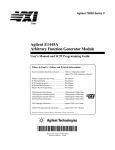
Specifications
Filter characteristics for nominal analog alias filter
2-20
HP E1430A User’s Guide
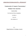
Specifications
Filter characteristics for 3rd pass digital filter + analog filter (dominated by digital)
2-21
HP E1430A User’s Guide
Specifications
Filter characteristics with all alias filtering turned off (based on approximate model)
2-22
3
Troubleshooting the
HP E1430A
3-1
HP E1430A User’s Guide
To troubleshoot using HP-IB interface
To troubleshoot using HP-IB interface
Equipment Required: ‘‘C’’ size mainframe
HP E1405/06A Command Module with HP E1430A SCPI driver
Series 200/300 computer with an HP-IB interface and RMBASIC
q Step 1.
Configure the system.
1 Set the mainframe’s power switch to standby (OI).
2 Set the HP E1405/06A Command Module’s HB-IB address to 0000 1001 (9).
3 Set the HP E1430A module’s logical address to 0000 1000 (8).
4 Connect an HP-IB cable from the computer to the command module’s HP-IB
port.
5 Set the mainframe’s power switch to on ( l ).
3-2
HP E1430A User’s Guide
To troubleshoot using HP-IB interface
q Step 2.
Test the HP E1430A module.
1 Type in and run the following program:
10
20
30
40
50
DIM Response$[80]
OUTPUT 70901;"*idn?"
ENTER 70901;Response$
DISP Response$
END
The response should be ‘‘Hewlett-Packard, E1430A, A.nn.nn,’’ where
A.nn.nn is the module’s software revision. If there is no response within 20
seconds, check your setup (cabling, address switch settings, baud rate),
verify that the E1430A SCPI driver is installed in the command module, and
run the program again.
2 Type in and run the following program:
10
20
30
40
50
OUTPUT 70901;"*tst?"
WAIT 150
ENTER 70901;Response$
DISP Response$
END
This test should take approximately 3 minutes.
3 If the response is +0, the self test has passed. If a failure is still suspected,
see ‘‘To troubleshoot using performance tests.’’
3-3
HP E1430A User’s Guide
To troubleshoot using HP-IB interface
4 If the response is +1, the HP E1430A module is faulty and an error message
is placed in the error queue. To read this message, type in and run the
following program:
10
30
40
50
OUTPUT 70901;"syst:err?"
ENTER 70901;Response$
DISP Response$
END
5 If the error message is ‘‘ADC Error’’ or ‘‘Overload,’’ perform the A/D
Converter adjustments. For all other error messages, replace the module.
See chapter 5, ‘‘Replaceable Parts,’’ for the replacement procedure and
exchange module part number.
3-4
HP E1430A User’s Guide
To troubleshoot using performance tests
To troubleshoot using performance tests
This section describes how each test is performed and how to troubleshoot
performance test failures. For more information, see page 2-7 (‘‘To run the
tests’’). A list of recommended test equipment is on page 2-3.
Caution
To protect circuits from static discharge, remove or replace modules only at
static-protected work stations.
1 Install and start the performance test software following the steps on page 2-5,
‘‘To start pt 1430 in the HP-UX environment,’’ or page 2-6, ‘‘To start pt 1430 in
the DOS environment.’’
2 Select and run the self test.
This test runs the diagnostic routines provided with the HP E1430A software
library. No external test equipment is needed. If a failure occurs check the
error message. If the error message is ‘‘ADC Error’’ or ‘‘Overload,’’ perform the
A/D Converter adjustments. For all other error messages, replace the module.
3 If there is no error message and a failure is still suspected, continue with the
following performance tests.
Amplitude Accuracy
This test uses an AC Calibrator to apply a voltage to the HP E1430A Input. The
AC Calibrator must use external sensing to avoid voltage drop due to cable
resistance. If the test fails, perform the A/D Converter adjustments.
Flatness
This test measures amplitude flatness by stepping a signal through the
frequency range. If a failure occurs, replace the module (flatness is not a field
adjustment).
Range Accuracy
This test measures the relative accuracy between ranges. A signal is applied to
the HP E1430A input and measured. The HP E1430A range is changed and the
same signal is measured again. The measurements are done on HP E1430A
ranges that use an internal 6dB attenuator to minimize any amplitude changes
due to return loss variation. If a failure occurs, replace the module.
Frequency Accuracy
This test measures the accuracy of the HP E1430A internal sample clock. The
HP E1430A measures a 4 MHz signal on a narrow (300 Hz) frequency span. The
measured frequency is used to compute sample clock error in Hz. If a failure
occurs, perform the frequency adjustment.
3-5
HP E1430A User’s Guide
To troubleshoot using performance tests
Distortion
This test measures harmonic distortion by using the HP E1430A’s internal
anti-alias filter to improve the distortion of a signal from a synthesizer. The test
frequency is chosen so a harmonic is aliased to about 4.5 MHz, where the
anti-alias filter will also reject synthesizer spurs. Measurements are done at two
amplitudes: nearly full scale and 20 dB below full scale. If a failure occurs,
replace the module.
Input Noise Density
This test measures residual noise in dB relative to full scale per Hz of
bandwidth. If a failure occurs, perform the A/D Converter adjustments. If the
test still fails, replace the module.
Spurious Responses
This test measures the level of some spurious residual responses. With no signal
applied, the HP E1430A does a measurement on the most sensitive range using
a 600 Hz frequency span centered around the frequency of a sub-harmonic of
the sample clock.
If a failure occurs, check that the screws are tight on the internal shields, the
module cover, and the module connections to the mainframe. If the test still
fails, replace the module.
Return Loss
This test measures the return loss of the HP E1430A input impedance. A
standard 50 Ohm reflection measurement is done on several HP E1430A ranges.
If a failure occurs, replace the module.
3-6
4
Adjusting the HP E1430A
4-1
HP E1430A User’s Guide
To adjust the module
To adjust the module
Caution
To protect circuits from static discharge, perform these adjustments only at
static-protected work stations.
This section contains the adjustment procedures for the HP E1430A. Use these
adjustments to return the module to specified operating accuracy if the
performance tests indicate a specification failure.
The HP E1430A is adjusted using the performance test software. Install and
start this software by following the steps on page 2-5 (‘‘To start pt1430 in the
HP-UX environment’’) and page 2-6 (‘‘To start pt1430 in the DOS
environment’’). Select ‘‘Adjust.seq’’ on the ‘‘Test Sequence’’ menu. This
sequence will prompt you to set up the test equipment and step you through the
adjustments.
The test equipment required for the adjustments is listed on page 2-3.
All adjustments can be done without removing the HP E1430A covers (see the
illustration below). The right side of the module must be accessible while it is in
the mainframe. A Hewlett-Packard VXI Development mainframe is
recommended. A standard VXI mainframe that has only the controller and the
HP E1430A module installed, on the left-hand side, can also be used.
Common Mode Balance
ADC1
Reference
ADC1 Offset
DC Offset
DAC2
Reference
DAC1 Reference
4-2
DAC3 Reference
Internal Time Base
HP E1430A User’s Guide
To adjust the module
Set up for adjusting and measuring common mode characteristics
The common mode source for measuring the common mode characteristics is a
sine wave voltage source applied through a 50 ohm series resister, as shown in
this diagram. See page 2-10 for more information about the common mode
characteristics.
50 ohm
feedthrough
Signal
Signal Ground
Attach clips to the
barrels of both
BNCs
Analog In
Ext Clk TTL
Synthesizer
HP E 1430A
BNC to
alligator clip
adapter
4-3
5
Replaceable Parts
5-1
HP E1430A User’s Guide
Replaceable Parts
Replaceable Parts
The HP E1430A VXI ADC Module’s circuit assemblies cannot be individually
replaced. The assemblies must be matched and adjusted at the factory.
Therefore, if the HP E1430A fails, order the exchange module. However,
selected hardware can be replaced if damaged. Replacement parts are listed in
the following three tables:
l
l
l
Caution
Module
Covers
Front Panel
The module is static sensitive. Use the appropriate precautions when removing,
handling, and installing to avoid unnecessary damage.
Ordering Information
To order a part listed in one of the tables, quote the Hewlett-Packard part
number (HP Part Number), the check digit (CD), indicate the quantity required,
and address the order to the nearest Hewlett-Packard sales and service office
(see the inside back cover of this guide). The check digit verifies that an order
has been transmitted correctly, ensuring accurate and timely processing of the
order. The first time a part is listed in the table, the quantity column (Qty) lists
the total quantity of the part used in the module. For the corresponding name
and address of the manufacturers’ codes shown in the tables, see ‘‘Code
Numbers.’’
Direct Mail Order System
Within the U.S.A., Hewlett-Packard can supply parts through a direct mail order
system. Advantages of the Direct Mail Order System are:
l
l
l
l
l
5-2
Direct ordering and shipment from the HP Parts Center.
No maximum or minimum on any mail order. There is a minimum order for parts
ordered through a local HP sales and service office when the orders require
billing and invoicing.
Transportation charges are prepaid. A small handling charge is added to each
order.
No invoicing. A check or money order must accompany each order.
Mail order forms and specific ordering information are available through your
local Hewlett-Packard sales and service office. See the inside back cover of this
guide for a list of Hewlett-Packard sales and service office locations and
addresses.
HP E1430A User’s Guide
Replaceable Parts
Code Numbers
The following table provides the name and address for the manufacturers’ code
numbers (Mfr Code) listed in the replaceable parts tables.
Mfr No.
Mfr Name
Address
05791
12085
28480
30817
83486
98291
Lyn Tron Inc.
Schlegel Corp.
Hewlett-Packard Company
Instrument Specialties Co. Inc.
ELCO Industries Inc.
ITT Sealectro
Burbank, CA 91505 U.S.A.
Rochester, NY 14692 U.S.A.
Palo Alto, CA 94304 U.S.A.
Placentia, CA 92670 U.S.A.
Rockford, IL 61101 U.S.A.
New Britain, CT 06051 U.S.A.
Module
Caution
Before installing the HP E1430A module into the VXI mainframe, be sure to set
the mainframe power switch to standby ( OI ) or remove power from the
mainframe. Inserting or removing the module with power on can damage the
module or mainframe.
Caution
To protect circuits from static discharge, remove or replace modules only at
static-protected work stations.
HP Part
Number
E1430-69201
E1430-69202
CD Qty
2
3
1
1
Description
HP E1430A EXCHANGE MODULE (STD) †
HP E1430A EXCHANGE MODULE (OPT AYD) †
Mfr
Code
28480
28480
Mfr Part
Number
E1430-69201
E1430-69202
† This information applies to modules with serial numbers ≥ 3419.
For modules with serial numbers < 3419, see chapter 6, ‘‘Backdating’’.
Do the following when you replace the HP E1430A module:
1 Write the faulty module’s serial number on the exchange module’s blank serial
number tag using a fine point permanent marker.
2 Write the faulty module’s serial number on the exchange module’s Certificate of
Calibration.
3 Remove all customer labels from the faulty module and place on the exchange
module.
4 Set the exchange module’s logical address configuration switch to the faulty
module’s original logical address for customer configuration convenience.
5-3
HP E1430A User’s Guide
Replaceable Parts
Covers
Ref
Des
HP Part
Number
MP100
MP101
MP102
MP103
MP104
E1430-00202
E1430-44101
E1485-40602
E1450-01202
E1430-44102
9
9
2
5
0
1
1
2
4
1
SHTF CVR-TOP ALSK
SHTF NSLTR-TOP PLCR
GSKT RFI-FRT PNL,ADH LG SD
STMP SHLD-RFI GRND "VXI"
SHTF NSLTR-BTTM PLCR
28480
28480
12085
28480
28480
E1430-00202
E1430-44101
5774-191W-0
E1450-01202
E1430-44102
MP105
MP107
MP108
MP109
MP110
E1485-40601
8160-0686
0515-1135
0380-2070
0515-0372
1
6
7
4
2
2
1
4
4
4
GSKT-RFI,BTTM CVR ADH SHT SD
STMP FNGRS-RFI STRP BECU
SCREW-MACH M3 X 0.5 25MM-LG
STDF-HXMF M3.0 14.0MMLG SSTPA
SCREW-MACHINE ASSEMPLY M3 X 0.5 8MM-LG
12085
30817
28480
05791
28480
5774-194W-0
786-185
0515-1135
SS5172-14.0-01
0515-0372
MP111 E1430-00203
0
1
SHTF CVR-BOTTOM AL
28480
E1430-00203
5-4
CD Qty
Description
Mfr
Code
Mfr Part
Number
HP E1430A User’s Guide
Replaceable Parts
Front Panel
Ref
Des
HP Part
Number
MP200
MP201
MP202
MP203
MP204
0515-1968
E1400-84106
0515-1946
E1400-84105
0515-0368
4
2
8
1
6
2
1
1
1
2
SCR-MCH M2.5 11MMLG PHSPS SST
MOLD KIT-TOP EXTR HNDL"HP"
SCR-MCH M3.0 6MMLG FHTX SST
MOLD KIT-BTTM EXTR HDL"VXI"
SCREW-MACHINE ASSEMPLY M2.5 X 0.45
28480
28480
28480
28480
28480
0515-1968
E1400-84106
0515-1946
E1400-84105
0515-0368
MP205
MP206
MP207
MP208
MP209
2190-0068
2950-0154
0515-1375
E1430-00201
2190-0124
5
2
7
8
4
3
3
2
1
4
WASHER-LK INTL T 1/2 IN .505-IN-ID
NUT-HEX-DBL-CHAM 1/2-28-THD .078-IN-THK
SCR-MCH M2.5 6MMLG FHTX SST
PNL-FRT "E1430A" VXI ALPT
WASHER-LK INTL T NO. 10 .195-IN-ID
28480
28480
83486
28480
98291
2190-0068
2950-0154
343-300-02506
E1430-00201
3002-26
9
4
NUT-HEX-DBL-CHAM 10-32-THD .067-IN-THK
98291
40001-18-030-156
MP210 2950-0078
CD Qty
Description
Mfr
Code
Mfr Part
Number
5-5
HP E1430A User’s Guide
To remove the front panel
To remove the front panel
1
Using a 1/4-inch nut driver, remove the
washers and nuts from the SMB connectors.
3
2
Using a 9/16-inch open-end wrench,
remove the washers and nuts from the BNC
connectors.
Using a T-8 torx driver, remove the screws that attach the handles. The screws come out from
below. The screws pass through a gold spacer; be careful not to lose the spacer when the handle is
removed.
5-6
HP E1430A User’s Guide
To remove the front panel
4
Using a T-10 torx driver, remove the screw
that attaches the front panel to the main
assembly.
5
To replace the front panel with another
that does not have its own side brackets,
remove the brackets from the old front panel.
Use a T-8 torx driver.
5-7
6
Backdating
6-1
HP E1430A User’s Guide
Backdating
Backdating
This chapter provides information necessary to modify this guide for modules
that differ from those currently being produced. The information in this chapter
documents earlier module configurations and associated servicing procedures.
With the information provided in this chapter, this guide can be corrected so
that it applies to any earlier version or configuration of the module.
If module serial number prefix is
Make change
≤ 3245A
< 3419
A
B
Change A
The external clock in these modules is a single-ended BNC input that requires
TTL levels. The following changes should be made to the manual.
l
On page 2-16 , Clock I/O Connections, ‘‘External ADC clock input (ExtClk):’’
should be changed to read ‘‘BNC input compatible with TTL. AC coupled with
input impedance of 1 kohm above 10 kHz. ±10 V absolute maximum input
without damage.’’
On page 6-2 , External Connections, ‘‘External Clock Input (Ext Clk)’’ should
be changed to read ‘‘This is a single-ended BNC input for TTL signals. The
module can be programmed to use the positive edges of this signal as the ADC
sample clock.’’
On page 6-7 , Clock Generation, paragraph 1, the last sentence should be
changed to read ‘‘This signal must be TTL.’’
l
l
Change B
The following table contains the information necessary to replace modules with
serial numbers < 3419. The procedure for replacing the module is on page 5-3.
HP Part
Number
E1430-69211
E1430-69212
6-2
CD Qty
4
5
1
1
Description
HP E1430A EXCHANGE MODULE (STD)
HP E1430A EXCHANGE MODULE (OPT AYD)
Mfr
Code
28480
28480
Mfr Part
Number
E1430-69211
E1430-69212
7
Circuit Descriptions
7-1
HP E1430A User’s Guide
Block Diagram and Description
Block Diagram and Description
Input Amplifier
The input amplifier provides an input termination which maintains good flatness
to 4 MHz. The gain/attenuation of the input amplifier is programmable.
Under program control, the input signal can be ac coupled. This allows the
system to measure low level ac signals in the presence of a large dc offset. The
input can also be programmed to eliminate any dc offset.
Anti-alias Filter
Since the normal ADC sample rate is 10 MHz, a complete representation of the
input signal can be achieved only for bandwidths up to 5 MHz. Frequency
components above 5 MHz can cause ambiguous results (aliasing).
The anti-alias filter attenuates these high frequency components to reduce
aliasing. The anti-alias filter in the HP E1430A is flat to 4 MHz and rejects
signals above 6 MHz by at least 100 dB. Thus the 0-4 MHz frequency range of
the sampled signal will be alias free. The filter’s transition band from 4 MHz to
6 MHz will affect flatness and allow some aliasing in the sampled signal
frequency range of 4 MHz-5 MHz.
In cases where alias filtering is not necessary the HP E1430A can be
programmed to bypass the anti-alias filter. This allows the system to take
advantage of the full 20 MHz sampler bandwidth. To avoid incorrect results, the
alias filter bypass mode should be used with caution; it is not recommended for
normal operation.
Sampling ADC
The heart of the HP E1430A is a precision Analog-to-Digital Converter (ADC).
The ADC generates 23 bit outputs at a sample rate up to 10.24 MHz. It has very
low noise density and very low distortion levels.
7-2
HP E1430A User’s Guide
Block Diagram and Description
7-3
HP E1430A User’s Guide
Block Diagram and Description
Zoom and Decimation Filtering
This section uses digital circuitry to allow programmable changes in the center
frequency and signal bandwidth of the HP E1430A (zoom). This is done at high
speed for real-time operation.
Bandwidth is controlled by a chain of digital low-pass filters (see the diagram on
the next page). Each of the filters reduces the bandwidth by a factor of two
(decimation). With the ADC sample rate (Fs) set to the standard internal
10 MHz rate, the bandwidth choices are ±5 MHz, ±2.5 MHz,...±0.289 Hz around
the programmed local-oscillator (LO) frequency.
Real and imaginary components of the signal are each computed to 32-bit
precision, so the complex output of the decimation filtering block contains
64 bits. Whether or not all of these bits are stored in memory is programmable.
7-4
HP E1430A User’s Guide
Block Diagram and Description
Data Formatting and FIFO Memory
The HP E1430A can be programmed to save the real component of the signal or
to save the complete complex signal. The data precision can be set to 16 bits or
32 bits. Thus, each sample will occupy from two to eight bytes of memory in the
FIFO. The data formatting block packs the selected data into 64-bit words
which are stored in the FIFO memory. Since the standard FIFO depth is
1-Mword (8 MB), it is possible to hold up to 4-Msamples in memory at one time.
The memory may be configured either in block mode or in continuous mode. In
block mode, data collection initiated by a trigger will proceed until a specified
block length is captured. The measurement is then paused so that the data can
be read out. Before a new block can be collected, the module must be re-armed
and triggered again. This mode is useful in capturing single transient events or
whenever the output data rate is too high to be read and processed in real time.
In continuous mode, data collection is initiated by a trigger and will continue as
long as the FIFO does not overflow. Data may be read out of the memory while
the measurement is in progress. If the reading of data is sufficiently fast, the
FIFO will never overflow and the measurement will continue indefinitely. If the
FIFO should ever overflow then the measurement will stop and wait for data to
be read out, the measurement to be re-armed, and a new trigger. This mode of
operation is useful for real-time applications that employ a high speed signal
processor to continuously read and operate on each sample of data. Data can be
read from the FIFO in bursts to accommodate pauses for such things as disk
access times or block mode computations.
The effective trigger time may be offset from the actual trigger event by
programming a trigger timing offset. Pre-trigger offset is limited to the physical
depth of the FIFO memory. Post-trigger offset is limited to 225 samples.
7-5
HP E1430A User’s Guide
Block Diagram and Description
Data Output
There are two ways to output data from the HP E1430A: by way of the VXI
backplane or by way of the local bus.
To use the VXI backplane, the HP E1430A can be programmed so that the
output of the FIFO is sent to the Send Data register. Each 64-bit portion of the
FIFO memory is sent to the 16-bit register as four separate words. The register
can then be read by any controller compatible with the VME standard.
Maximum data flow is about 2 MB/s.
The local bus allows data transfers over a high speed 8-bit ECL bus to an
adjacent module (to the right) in the VXI mainframe. Multiple adjacent
HP E1430A modules can send data to one signal processor module. The signal
processor must be one which supports the Hewlett-Packard ECL local bus
protocol, such as the HP E1485A/B. In addition to higher speed (up to 40
MB/s), the local bus has the advantage that data can be output at the same time
that control signals are being sent over the VXI backplane.
In both of the data output modes, the samples must be read out sequentially,
beginning with the sample following the trigger.
7-6
HP E1430A User’s Guide
Block Diagram and Description
Clock Generation
The usual source for a clock signal is the 10 MHz (or optional 10.24 MHz) crystal
oscillator inside the HP E1430A. However, the HP E1430A can also accept an
external clock signal through a front-panel BNC (‘‘Ext Clk’’). This signal can be
TTL, ECL, or sine wave.
In a system using more than one HP E1430A, the ADCs can be synchronized by
programming them to use a common ECL line on the backplane. One of the
modules can be the clock master that drives this line. This backplane clock can
be extended to other mainframes by connecting the ‘‘Clk Out’’ SMB connector to
the ‘‘Clk In’’ SMB connector on an HP E1430A in the second mainframe.
7-7
HP E1430A User’s Guide
Block Diagram and Description
Trigger
The trigger event used to start a measurement can be generated in four
different ways:
•
•
•
•
Software trigger
External TTL
ADC threshold
Log-magnitude
All triggering modes support slope selection. In ADC or log-magnitude mode
the trigger threshold can be specified with hysteresis to prevent noise-generated
triggers of the wrong slope. Log-magnitude triggering is based on the
magnitude of the complex signal after zooming and filtering.
For external TTL mode, a trigger signal must be supplied at the ‘‘Ext Trg TTL’’
connector on the front panel.
Any HP E1430A module can trigger other HP E1430A modules using a shared
sync line on the VXI backplane. This backplane sync line can be extended to
other mainframes by connecting the ‘‘Sync Out’’ SMB connector to the ‘‘Sync In’’
SMB connector on a HP E1430A in the second mainframe. All modules in a
synchronous system are triggered on the same ADC sample.
The HP E1430A hardware samples the trigger source once every sample clock,
so the trigger condition must be present for at least one sample clock in order
to be recognized.
7-8
HP E1430A User’s Guide
Block Diagram and Description
Control Registers
The HP E1430A module is controlled using registers mapped into the 16-bit VXI
address space. There are 24 writable and 18 readable registers; each has 16 bits.
7-9
8
Using the HP E1430A
8-1
Front-panel Description
Status LEDs
Access
This LED lights whenever the module is being accessed via the VXI backplane.
Overload
This LED lights when the input range is exceeded, producing an overload in the
ADC.
External Connections
Analog Input (Analog In)
This BNC connector is the main input to the ADC. It is a pseudo-floating
single-ended input terminated into 50 ohms. The maximum signal level without
damage is 7 volts rms.
External Clock Input (Ext Clk)
This is a single-ended BNC input for TTL, ECL, or sine wave signals. The
module can be programmed to use the positive edges of this signal as the ADC
sample clock.
Trigger Input (Ext Trg TTL)
This is a single-ended BNC input for TTL signals. The module can be
programmed to use the positive or negative edges of this signal to trigger the
acquisition of a block of data.
Sync Extender Output (Sync Out)
This SMB connector is an ECL output with a buffered version of the backplane
sync line used for synchronization and triggering. It is used to extend the sync
line from one mainframe to another.
Clock Extender Output (Clk Out)
This SMB connector is an ECL output with a buffered version of the sample
clock line on the backplane of the mainframe. It is used to extend the sample
clock from one mainframe to another.
Sync Extender Input (Sync In)
This SMB connector is an ECL input used to drive the sync line on the
backplane of the mainframe with a sync signal generated in another mainframe.
The signal must be supplied from the ‘‘Sync Out’’ connector of an HP E1430A
module in the driving mainframe.
8-2
Clock Extender Input (Clk In)
This SMB connector is an ECL input used to drive the sample clock line on the
backplane of the mainframe with a clock signal generated in another mainframe.
Normally the signal is supplied from the ‘‘Clk Out’’ connector of an HP E1430A
module in the driving mainframe. This input can also be driven by an external
ADC clock generator using ECL levels.
HP E1430A Front Panel
8-3
VXI Backplane Connections
Power Supplies and Ground
The HP E1430A conforms to the VME and VXI specifications for pin assignment.
The current drawn from each supply is given in chapter 2, ‘‘Verifying
Specifications.’’
Data Transfer Bus
The HP E1430A conforms to the VME and VXI specifications for pin assignment
and protocol. Only A16/D16 data transfers are supported. Thus the upper
address and data bits are ignored.
DTB Arbitration Bus
The HP E1430A module is not capable of requesting bus control. Thus it does
not use the Arbitration bus. To conform to the VME and VXI specifications, it
passes the bus lines through.
Priority Interrupt Bus
The HP E1430A generates interrupts by applying a programmable mask to its
status bits. The priority of the interrupt is determined by the interrupt priority
setting in the control register.
Utility Bus
The VME specification provides a set of lines collectively called the utility bus.
Of these lines, the HP E1430A only uses the SYSRESET* line.
Pulling the SYSRESET* line low (a hardware reset) has the same effect as
setting the reset bit in the Control Register (a software reset), with two
exceptions. The exceptions are:
• The Control Register is also reset.
• All logic arrays are reloaded.
Reloading the logic arrays enables the hardware reset to recover from power
dropouts which may invalidate the logic setup.
8-4
Local Bus
The VXI specification includes a 12-wire local bus between adjacent module
slots. Using the local bus, Hewlett-Packard has defined a standard byte-wide
ECL protocol that transfers data from left to right at up to 100 Mbyte/s. The
HP E1430A can be programmed to output its data using this high speed port
instead of the VME data output register. The Data Port Control register
determines which output port is used.
Trigger Lines
The VXI specification provides 8 TTL and 2 ECL trigger lines which can be used
for module-specific signaling. When programmed in a multi-input configuration,
the HP E1430A uses the ECL trigger lines, designating ECLTRG0 as the SYNC
line and ECLTRG1 as the ADC sample clock (CLOCK). These lines can be
extended to other mainframes using the SMB connectors on the front panel.
The CLOCK line is the master ADC clock for a synchronous system of multiple
HP E1430A modules. Only one HP E1430A module in each mainframe is
allowed to drive this line.
The SYNC line is used to send timing signals among HP E1430A modules in a
multi-input system. Any module which drives this line must do so synchronously
with CLOCK so that transitions on SYNC do not occur near the rising edge of
CLOCK. This ensures that all modules with a synchronous state machine
clocked on CLOCK will interpret SYNC in a consistent manner for each cycle of
the state machine. SYNC is used for synchronizing, arming, and triggering
signals between HP E1430A modules. The interpretation of the SYNC line is
dependent on the states of the module described in the Measurement Loop
section. The E1430A module is also capable of controlling the SYNC line
synchronously via the Measurement Control Register.
8-5
9
Programming
the HP E1430A with
the C Interface Libraries
9-1
HP E1430A User’s Guide
The C Interface Libraries for the HP E1430A are a set of functions that
allow you to program the register-based HP E1430A at a higher level
than register reads and writes. The libraries allow groups of HP E1430As
to be set up and programmed as if they were one entity. The current
state of each HP E1430A in a system is maintained in your host computer
because you cannot read from many of the HP E1430A’s registers you
can write to. These states can be saved and restored. The libraries
include routines to perform auto-ranging and autozeroing, routines to aid
debugging and hardware diagnostic routines. In addition, there are
low-level routines to allow direct register access, but with the added
protection of bus error trapping.
The libraries are designed to work both in the Series 300 and Series 700
UNIX environment, in the Series 700 UNIX/MXI environment, and in the
HP E1485A/B environment. The library must be used in one
environment or the other, but not both at the same time. This
restriction is necessary since the libraries maintain internal state
information about the HP E1430A that could become corrupted if two
sources are changing the HP E1430A’s registers.
UNIX is a registered trademark of UNIX System Laboratories Inc. in the U.S.A. and other countries
9-2
HP E1430A User’s Guide
Getting Started
Getting Started
For instructions on how to install the C Interface Libraries, see Chapter 1,
“Installing the HP E1430A.”
Compiling and Linking Your Program
How you compile and link the libraries to your program depends on the
operating environment.
HP-UX Environment
Here is an example of the linker line in the make file in an HP-UX environment:
cc -o<program name> <object files> /usr/e1430/lib/lib1430.a
-lsicl -lc -lm
HP E1485A Environment
Here is an example of the linker line in the make file in an HP E1485A
environment using the GNU compiler supplied with HP E1485A Programmer’s
Toolkit 2.0:
/usr/e1485/gcc/gcc -B/usr/gcc/gcc -nostdlib -d -r -N
\<object files> /usr/e1485/lib/libspil.o -o <program name>
Here is an example of the linker line in older versions of the toolkit that are
compiled with cc:
ld -dr -N -a archive /usr/e1485/lib/libspil.o <object files> \
/usr/e1430/libd1430.a /usr/e1485/lib/libsrf.a -o <program name>
Note
See the HP E1485A/B Programmer’s Reference manual for more information on
developing code in the HP E1485A environment.
9-3
HP E1430A User’s Guide
Getting Started
Debugging
There are several levels of debugging aids provided with the libraries. First, you
should check the return value of all functions. Usually, a non-zero value denotes
an error.
The e1430_print_errors function can be called to enable/disable an error
printing mechanism. If error printing is enabled, an error message will be
printed by any function returning an error. If the libraries are used in a host
computer environment, the errors are output to stdout (normally the console
screen). If the libraries are used in the HP E1485A/B environment, the error
messages will be output to a terminal connected to the RS-232-C port available
on this module. It is normal while developing code to include a call to
e1430_print_errors enabling error printing early in the code. Once the code
has been fully debugged, you should remove this call.
There are functions for dumping individual registers or the complete state of a
group of HP E1430As in an easy-to-read format. See ‘‘Debugging’’ under the
C-libraries Quick Reference (by Category)following this section.
The function, e1430_debug_level, is used to print out a message each time a
register write occurs to the HP E1430A. The message includes the register
number and new contents being written. This function allows the detailed
examination of a sequence of register writes as well as the contents of the
HP E1430A registers at the bit level.
Diagnostics
The HP E1430A library comes with a set of diagnostic functions that test various
sections of HP E1430A hardware and perform calibration. These functions can
be called individually, or the entire diagnostic suite can be run. In addition, a
standalone diagnostic program, test1430, is included with the software shipped
with the HP E1430A.
Data Format
An HP E1430A can collect either real or complex data in 16-bit or 32-bit format.
It can collect data into various blocksizes or in a continuous mode. This data
can be transferred either through a register on the VXI backplane or over the
local bus. Status information can be appended to each block of data indicating
ADC overloads or ADC errors during the block.
Decimation Filter
The decimation filter provides bandpass filtering (low pass for baseband) and
decimation capabilities. It is possible to program the filter to interleave output
data from more than one stage of the filter, which is useful for octave type
measurements.
9-4
HP E1430A User’s Guide
Getting Started
Triggering
An HP E1430A can be triggered to collect data in a variety of ways. The trigger
can be internally generated or can come from an external source. Multiple
modules can be triggered synchronously. A variable pre and post trigger delay
can be programmed for data collection. The slope and level of the trigger point
on a signal can be selected. The source of the internal trigger can be either the
output of the ADC or the magnitude of the complex output of the decimation
filter. When in the magnitude triggering mode the trigger bandwidth out of the
decimation filter can be selected independently of the bandwidth (span) of the
data that is passed on out of the module.
Managing Multiple Mainframe Measurements
In a single mainframe measurement, the HP E1430A communicates with other
HP E1430As through the TTLTRG lines. However, when using the VXI-MXI bus
extender modules, the TTLTRG lines, which carry the group synchronization
pulse and sample clock, are extended only in one direction. This unidirectional
signal connection restricts the types of measurements you can make in a
multiple mainframe environment.
You cannot perform the following types of multiple mainframe measurements:
•
•
•
•
unequal pre-trigger delay settings between mainframes
channel triggering by channels in Mainframe B
lower spans or longer blocksizes in Mainframe B
different digital filter settling times between HP E1430A modules
Programming Specific Modules Contained in a Single Module Group
When using multiple HP E1430A modules with the ADC clocks synchronized, all
modules share a common ADC clock and a common sync signal. Both of these
are distributed across the VXI backplane. Since the SYNC line is used for
multiple purposes (triggering, synchronizing local oscillators, and synchronizing
decimation) it is important that all modules agree on the meaning of each SYNC
line transition.
All modules in the mainframe which are programmed to use these shared
resources must be placed in a single module group created by
e1430_create_module_group. Since most of the library functions program all
modules in a group simultaneously, they will normally have the same setup
parameters.
One way to get different setups among the modules is to create additional
groups, each of which contains a subset of the modules in the system. In the
extreme, a sub-group of one module could be defined for each module in the
system. There is a problem with this approach.
9-5
HP E1430A User’s Guide
Getting Started
Many of the setup functions in the library check to see if a module is configured
with the E1430_MULTI_SYNC_ON command. If it is, these functions use the
SYNC line to program the modules in such a way as to maintain synchronization
of the local oscillators and decimators. If any of these functions are called using
one of the sub-group identifiers, the manipulation of the SYNC line is
interpreted incorrectly by other modules which are not part of the sub-group.
Thus none of these functions can be used for sub-group programming once the
multi-sync mode has been set.
To establish different setups for these functions among the modules in a
synchronous group, use the e1430_write_register_image command. This
command will write directly to registers at individual logical addresses without
using group IDs at all. This circumvents the check for multi_sync_on and allows
setup without using the SYNC line. For example, block mode, data type, data
precision, and zoom span can all be set up for an individual module by writing
the appropriate value to register 12 (decimal). The registers are described in
chapter 12, ‘‘VXI Registers’’.
Functions not listed in the following table may still be used for sub-groups even
in systems with MULTI_SYNC_ON. For example, e1430_set_analog_input may
be used to set up different ranges without having to resort to the lower level
direct register writes. The direct register writes would work as well, removing
the need to create the sub-groups at all.
The following functions should not be used for subgroups
with MULTI_SYNC_ON:
e1430_abort_meas
e1430_arm_module
e1430_auto zero
e1430_diagnostics
e1430_read_float32_data
e1430_read_raw_data
e1430_reset_dsp
e1430_reset_module
e1430_set_data_size
e1430_set_data_type
e1430_set_decimation_bandwidth
e1430_set_decimation_filter
e1430_set_decimation_output
e1430_set_decimation_passtag
e1430_set_decimation_states
e1430_set_span_zoom
e1430_set_append_status
e1430_set_blocksize
e1430_set_center_frequency
e1430_set_data_format
e1430_test_fifo_memory
e1430_test_interrupts
e1430_test_meas_control
e1430_test_trigger
e1430_set_data_mode
e1430_trigger_module
9-6
HP E1430A User’s Guide
C Libraries Quick Reference (by Category)
C Libraries Quick Reference (by Category)
I n it ia liz a tio n
A user program must first intitialize the I/O driver and set up at least one module group.
An HP E1430A can be reset and the timeout for I/O operations set optionally.
F u n ct io n
D e cr ip t io n
e1430_init_io_driver
e1430_create_module_group
e1430_delete_module_group
e1430_delete_all_module_groups
e1430_get_timeout
e1430_set_timeout
Initialize I/O driver
Create a group of HP E1430A modules
Delete a group of HP E1430A modules
Delete all groups of HP E1430A modules
Get value of timeout for I/O operations
Set value of timeout for I/O operations
P a ge n u m b e r
10- 18
10- 5
10- 5
10- 5
10- 67
10- 67
C o n figu r in g t h e A n a lo g I n p u t s
F u n ct io n
D e cr ip tio n
e1430_auto zero
e1430_auto_range
e1430_set_analog_input
e1430_set_range
e1430_get_range
e1430_set_range-la
e1430_get_range_la
e1430_set_anti_alias_filter
e1430_get_anti_alias_filter
e1430_set_coupling
e1430_get_coupling
Null out input DC offset
Set range at level to avoid ADC overload
Set all analog setup parameters
Set range of all HP E1430As in a group
Get current range of all HP E1430As in a group
Set range of HP E1430A at a logical address
Get range of HP E1430A at a logical address
Include/bypass input anti-alias filter
Get current state of anti-alias filter
Set input coupling to AC or DC
Get current state of input coupling
e1430_set_input_high
e1430_get_input_high
e1430_set_input_low
e1430_get_input_low
e1430_get_input_offset
e1430_set_input_offset
Set source of input signal to ADC
Get current source of input signal
Set input connector shield to float or ground
Get state of input connector shield
Get the value of the input offset DAC
Set the value of the input offset DAC
Pa g e n u m b e r
10-4
10-4
10-26
10-62
10-62
10-62
10-62
10-28
10-28
10-36
10-36
10-54
10-54
10-54
10-54
10-56
10-56
9-7
HP E1430A User’s Guide
C Libraries Quick Reference (by Category)
D a ta F o r m a t
F u n ct io n
D e cr ip t io n
P a ge n u m b e r
e1430_set_data_format
e1430_set_data_port
e1430_get_data_port
e1430_set_lbus_mode
Set all data format parameters except data port
Set data port to VME or Local Bus
Get current data port
Set the transmission mode of the Local Bus
e1430_get_lbus_mode
e1430_set_data_mode
e1430_get_data_mode
e1430_set_append_status
e1430_get_append_status
e1430_set_data_type
e1430_get_data_type
e1430_get_data_reread
e1430_set_data_reread
e1430_set_data_size
e1430_get_data_size
e1430_set_blocksize
e1430_get_blocksize
Get the transmission mode of the Local Bus
Set data collection to block or continuous mode
Get current data collection mode
Enable/disable appending status onto data
Get current state of append status switch
Set data type to real or complex
Get current value of data type
Get current reread state
Set FIFO to continuous reread of block
Set data size to 16 or 32 bits
Get current value of data size
Set blocksize
Get current blocksize
10-37
10-40
10-40
10-59
10-59
10-39
10-39
10-29
10-29
10-43
10-43
10-41
10-41
10-42
10-42
10-30
10-30
T r igge r
F u n ct io n
D e cr ip t io n
e1430_set_trigger_mode
e1430_set_trigger_source
e1430_get_trigger_source
e1430_set_trigger_slope
e1430_get_trigger_slope
e1430_set_trigger_level_adc
e1430_get_trigger_level_adc
e1430_set_trigger_level_mag
e1430_get_trigger_level_mag
e1430_set_trigger_delay
e1430_get_trigger_delay
e1430_get_trigger_bandwidth
e1430_get_trigger_phase
9-8
Set all trigger setup parameters
Set source of trigger
Get current source of trigger
Set slope of trigger
Get current slope of trigger
Set trigger level for ADC triggering
Get current ADC triggering level
Set trigger level for magnitude triggering
Get current magnitude triggering level
Set trigger delay
Get current trigger delay
Get current trigger bandwidth
Get current trigger phase
P a ge n u m b e r
10-72
10-76
10-76
10-75
10-75
10-70
10-70
10-71
10-71
10-68
10-68
10-44
10-17
HP E1430A User’s Guide
C Libraries Quick Reference (by Category)
D e cim a tio n F ilt e r
F u n ctio n
D e cr ip tio n
P a ge n u m b e r
e1430_set_decimation_filter
e1430_set_decimation_bandwidth
e1430_get_decimation_bandwidth
e1430_set_decimation_state
Set all decimation filter parameters
Set data and trigger bandwidths and decimation
Get current data bandwidth (span)
Enable/disable extra X2 decimation
e1430_get_decimation_state
e1430_set_decimation_output
e1430_get_decimation_output
e1430_set_decimation_passtag
e1430_get_decimation_passtag
Get current state of extra decimation
Set filter output as one pass or multi-pass
Get current state of output
Set position of tag on multi-pass data
Get position of tage on data
10-46
10-44
10-44
10-52
10-52
10-49
10-49
10-50
10-50
M e a su r e m e n t
F u n ct io n
D e cr ip t io n
e1430_abort_meas
e1430_arm_module
e1430_get_center_frequency
e1430_get_span
e1430_reset_module
Move HP E1430A to IDLE state
Move HP E1430A to ARM state
Get current center frequency
Get span
Reset all HP E1430As in a group
e1430_reset_dsp
e1430_reset_lbus
e1430_set_center_frequency
e1430_trigger_module
e1430_set_span_zoom
Reset local oscillator phase and decimation filters
Reset local bus on all HP E1430As in a group
Set center frequency
Trigger HP E1430A programatically
Set center frequency, span, and zoom at one time
P a ge n u m b e r
10-2
10-3
10-31
10-65
10-23
10-21
10-22
10-31
10-78
10-65
R e a d in g D a t a
F u n ct io n
D e cr ip t io n
e1430_read_raw_data
e1430_get_scale_la
e1430_read_float32_data
e1430_get_fifo_block_data_size
e1430_get_fifo_size
Read raw data from HP E1430A
Get data scaling factor of HP E1430A
Read scaled float data from HP E1430A
Return size in bytes of block of data
Return size in bytes of FIFO
e1430_get_fifo_data_point_size
e1430_get_fifo_max_blocksize
Return size in bytes of one sample
Return size in samples of maximum block
P a ge n u m b e r
10-19
10-19
10-19
10-13
10-13
10-13
10-13
9-9
HP E1430A User’s Guide
C Libraries Quick Reference (by Category)
T im in g
F u n ct io n
D e cr ip t io n
e1430_set_clock_mode
e1430_set_clock_master_mode
e1430_set_adc_clock
e1430_get_adc_clock
Set all trigger setup parameters
Enable an HP E1430A to drive VXI clock line
Set ADC clock source
Get current value of ADC clock source
e1430_set_dsp_clock
e1430_get_dsp_clock
e1430_set_multi_sync
e1430_get_multi_sync
e1430_get_sample_clock_freq_la
e1430_set_sample_clock_freq_la
Set DSP clock source
Get current value of DSP clock source
Set multi-module synchronization
Get current multi-module sync state
Get sample clock frequency
Set external sample clock frequency
P a ge n u m b e r
10-34
10-32
10-25
10-25
10-53
10-53
10-60
10-60
10-64
10-64
I nterru pts
F u n ct io n
D e cr ip t io n
e1430_set_interrupt
e1430_set_interrupt_priority
e1430_get_interrupt_priority
e1430_set_interrupt_mask
e1430_get_interrupt_mask
Sets all interrupt parameters
Set interrupt priority
Get current interrupt priority
Set interrupt mask
Get current interrupt mask
P a ge n u m b e r
10-57
10-57
10-57
10-57
10-57
R e g ist e r R e a d /W r it e
F u n ct io n
D e cr ip t io n
E1430_TRY
E1430_RECOVER
e1430_get_register_address
e1430_set_try_recover
e1430_write_register
e1430_write_register_card
e1430_write_register_image
e1430_read_register_card
e1430_read_register_image
Bracket code with these to trap bus errors
Get memory mapped address of HP E1430A register
Turn TRY-RECOVER mechanism on or off
Register write to all HP E1430As in group
Register write to one HP E1430A only
Register write to one HP E1430A and image
Register read of one HP E1430A
Register read of internal image of HP E1430A
P a ge n u m b e r
*
10-14
10-14
10-79
10-79
10-79
10-79
10-79
*These macro definitions are included to be able to trap bus errors when doing direct accesses on a register.
9-10
HP E1430A User’s Guide
C Libraries Quick Reference (by Category)
D ia g n o st ics a n d C a lib r a t io n
F u n ct io n
D e cr ip t io n
e1430_diagnostics
e1430_test_logical_address
e1430_test_register_access
e1430_test_meas_control
Perform all HP E1430A diagnostics
Verify decoding of logical addresses
Verify register access
Verify measurement loop
e1430_test_timing_setup
e1430_test_fifo_memory
e1430_test_data_collection
e1430_test_trigger
e1430_test_interrupts
Verify ADC and DSP clock sources
Verify FIFO memory
Verify data collection modes
Verifies proper operation of trigger modes
Verify interrrupt modes
P a ge n u m b e r
10-9
10-9
10-9
10-9
10-9
10-9
10-9
10- 9
10-9
D e b u g gin g
F u n ct io n
D e cr ip t io n
P a ge n u m b e r
e1430_display_module_state
e1430_display_register
e1430_get_module_state
e1430_print_errors
e1430_get_error_string
Dump HP E1430A state in easy to read format
Dump contents of an HP E1430A register
Return internal HP E1430A state
Enable/disable function error printout
Points to most recent error returned
e1430_debug_level
Enable/disable register write printout
10-7
10-7
10-7
10-7
10- 7
10-7
P o st P r o ce ssin g D a ta
F u n ct io n
e1430_get_filter
e1430_get_resample
D e cr ip t io n
Filter time domain data
Filter and resample time domain data
P a ge n u m b e r
10- 11
10-15
9-11
HP E1430A User’s Guide
C Libraries Quick Reference (Alphabetical)
C Libraries Quick Reference (Alphabetical)
F u n ct io n
D e scr ip t io n
e1430_abort_meas
e1430_arm_module
e1430_auto zero
e1430_auto_range
e1430_create_module_group
e1430_debug_level
e1430_delete_all_module_groups
Move HP E1430A to IDLE state
Move HP E1430A to ARM state
Null out input DC offset
Set range at level to avoid ADC overload
Create a group of HP E1430A modules
Enable/disable register write printout
Delete all groups of HP E1430A modules
e1430_delete_module_group
e1430_diagnostics
e1430_display_module_state
e1430_display_register
e1430_get_adc_clock
e1430_get_anti_alias_filter
e1430_get_append_status
e1430_get_blocksize
Delete a group of HP E1430A modules
Perform all HP E1430A diagnostics
Dump HP E1430A state in easy to read format
Dump contents of an HP E1430A register
Get current value of ADC clock source
Get current state of anti-alias filter
Get current state of append status switch
Get current blocksize
e1430_get_center_frequency
e1430_get_coupling
e1430_get_data_mode
e1430_get_data_port
e1430_get_data_reread
e1430_get_data_size
e1430_get_data_type
e1430_get_decimation_bandwidth
Get current center frequency
Get current state of input coupling
Get current data collection mode
Get current data port
Get current reread state
Get current value of data size
Get current value of data type
Get current data bandwidth (span)
e1430_get_decimation_output
e1430_get_decimation_passtag
e1430_get_decimation_state
e1430_get_dsp_clock
e1430_get_error_string
e1430_get_fifo_block_data_size
e1430_get_fifo_data_point_size
e1430_get_fifo_max_blocksize
e1430_get_fifo_size
e1430_get_filter
Get current state of output
Get position of tage on data
Get current state of extra decimation
Get current value of DSP clock source
Points to most recent error returned
Return size in bytes of block of data
Return size in bytes of one sample
Return size in samples of maximum block
Return size in bytes of FIFO
Filter time domain data
9-12
P a ge n u m b e r
10-2
10-3
10-4
10-4
10- 5
10-7
10- 5
10- 5
10-9
10-7
10-7
10-25
10-28
10-29
10-30
10-31
10-36
10-39
10-40
10-41
10-42
10-43
10-44
10-49
10-50
10-52
10-53
10- 7
10-13
10-13
10-13
10-13
10- 11
HP E1430A User’s Guide
C Libraries Quick Reference (Alphabetical)
F u n ct io n
D e scr ip t io n
e1430_get_input_high
e1430_get_input_low
e1430_get_input_offset
e1430_get_interrupt_mask
Get current source of input signal
Get state of input connector shield
Get the value of the input offset DAC
Get current interrupt mask
e1430_get_interrupt_priority
e1430_get_lbus_mode
e1430_get_module_state
e1430_get_multi_sync
e1430_get_range
e1430_get_range_la
e1430_get_register_address
e1430_get_resample
e1430_get_sample_clock_freq_la
e1430_get_scale_la
e1430_get_span
e1430_get_timeout
e1430_get_trigger_bandwidth
e1430_get_trigger_delay
e1430_get_trigger_level_adc
e1430_get_trigger_level_mag
e1430_get_trigger_phase
e1430_get_trigger_slope
e1430_get_trigger_source
e1430_init_io_driver
e1430_print_errors
e1430_read_float32_data
e1430_read_raw_data
e1430_read_register_card
e1430_read_register_image
e1430_reset_dsp
e1430_reset_lbus
e1430_reset_module
e1430_set_adc_clock
e1430_set_analog_input
e1430_set_anti_alias_filter
e1430_set_append_status
Get current interrupt priority
Get the transmission mode of the Local Bus
Return internal HP E1430A state
Get current multi-module sync state
Get current range of all HP E1430As in a group
Get range of HP E1430A at a logical address
Get memory mapped address of HP E1430A register
Filter and resample time domain data
Get sample clock frequency
Get data scaling factor of HP E1430A
Get span
Get value of timeout for I/O operations
Get current trigger bandwidth
Get current trigger delay
Get current ADC triggering level
Get current magnitude triggering level
Get current trigger phase
Get current slope of trigger
Get current source of trigger
Initialize I/O driver
Enable/disable function error printout
Read scaled float data from HP E1430A
Read raw data from HP E1430A
Register read of one HP E1430A
Register read of internal image of HP E1430A
Reset local oscillator phase and decimation filters
Reset local bus on all HP E1430As in a group
Reset all HP E1430As in a group
Set ADC clock source
Set all analog setup parameters
Include/bypass input anti-alias filter
Enable/disable appending status onto data
Pa g e N u m b e r
10-54
10-54
10-56
10-57
10-57
10-59
10-7
10-60
10-62
10-62
10-14
10-15
10-64
10-19
10-65
10- 67
10-44
10-68
10-70
10-71
10-17
10-75
10-76
10- 18
10-7
10-19
10-19
10-79
10-79
10-21
10-22
10-23
10-25
10-26
10-28
10-29
9-13
HP E1430A User’s Guide
C Libraries Quick Reference (Alphabetical)
F u n ct io n
D e scr ip t io n
e1430_set_blocksize
e1430_set_center_frequency
e1430_set_clock_master_mode
e1430_set_clock_mode
Set blocksize
Set center frequency
Enable an HP E1430A to drive VXI clock line
Set all trigger setup parameters
e1430_set_coupling
e1430_set_data_format
e1430_set_data_mode
e1430_set_data_port
e1430_set_data_reread
e1430_set_data_size
e1430_set_data_type
e1430_set_decimation_bandwidth
e1430_set_decimation_filter
e1430_set_decimation_output
e1430_set_decimation_passtag
e1430_set_decimation_state
e1430_set_dsp_clock
e1430_set_input_high
e1430_set_input_low
e1430_set_input_offset
e1430_set_interrupt
e1430_set_interrupt_mask
e1430_set_interrupt_priority
e1430_set_lbus_mode
e1430_set_multi_sync
e1430_set_range
e1430_set_range-la
e1430_set_sample_clock_freq_la
e1430_set_span_zoom
e1430_set_timeout
e1430_set_trigger_delay
e1430_set_trigger_level_adc
e1430_set_trigger_level_mag
e1430_set_trigger_mode
e1430_set_trigger_slope
e1430_set_trigger_source
Set input coupling to AC or DC
Set all data format parameters except data port
Set data collection to block or continuous mode
Set data port to VME or Local Bus
Set FIFO to continuous reread of block
Set data size to 16 or 32 bits
Set data type to real or complex
Set data and trigger bandwidths and decimation
Set all decimation filter parameters
Set filter output as one pass or multi-pass
Set position of tag on multi-pass data
Enable/disable extra X2 decimation
Set DSP clock source
Set source of input signal to ADC
Set input connector shield to float or ground
Set the value of the input offset DAC
Sets all interrupt parameters
Set interrupt mask
Set interrupt priority
Set the transmission mode of the Local Bus
Set multi-module synchronization
Set range of all HP E1430As in a group
Set range of HP E1430A at a logical address
Set external sample clock frequency
Set center frequency, span, and zoom at one time
Set value of timeout for I/O operations
Set trigger delay
Set trigger level for ADC triggering
Set trigger level for magnitude triggering
Set all trigger setup parameters
Set slope of trigger
Set source of trigger
9-14
Pa g e N u m b e r
10-30
10-31
10-32
10-34
10-36
10-37
10-39
10-40
10-41
10-42
10-43
10-44
10-46
10-49
10-50
10-52
10-53
10-54
10-54
10-56
10-57
10-57
10-57
10-59
10-60
10-62
10-62
10-64
10-65
10- 67
10-68
10-70
10-71
10-72
10-75
10-76
HP E1430A User’s Guide
C Libraries Quick Reference (Alphabetical)
F u n ct io n
D e scr ip t io n
e1430_set_try_recover
e1430_test_data_collection
e1430_test_fifo_memory
e1430_test_interrupts
Turn TRY-RECOVER mechanism on or off
Verify data collection modes
Verify FIFO memory
Verify interrrupt modes
e1430_test_logical_address
e1430_test_meas_control
e1430_test_register_access
e1430_test_timing_setup
e1430_test_trigger
e1430_trigger_module
E1430_TRY
E1430_RECOVER
e1430_write_register
e1430_write_register_card
e1430_write_register_image
Verify decoding of logical addresses
Verify measurement loop
Verify register access
Verify ADC and DSP clock sources
Verifies proper operation of trigger modes
Trigger HP E1430A programatically
Bracket code with these to trap bus errors
Register write to all HP E1430As in group
Register write to one HP E1430A only
Register write to one HP E1430A and image
Pa g e N u m b e r
10-14
10-9
10-9
10-9
10-9
10-9
10-9
10-9
10- 9
10-78
*
10-79
10-79
10-79
*These macro definitions are included to be able to trap bus errors when doing direct accesses on a register.
9-15
10
C Interface Library
Support Reference
10-1
HP E1430A User’s Guide
e1430_abort_meas
e1430_abort_meas
Abort measurement
SYNOPSIS
#include "e1430.h"
SHORTSIZ16 e1430_abort_meas(groupID)
SHORTSIZ16 groupID;
DESCRIPTION
E1430_abort_meas places all HP E1430As in the group into the IDLE state.
GroupID is the group ID of a single HP E1430A or group of HP E1430As that
was obtained by a call to e1430_create_module_group.
RETURN VALUE
Upon successful completion a value of 0 is returned. Otherwise an error will be
returned. The error, ERR1430_NO_GROUP, is returned if an illegal value of the
groupID parameter is used (i.e. one that was not obtained by a call to
e1430_create_module_group(E1430)).
SEE ALSO
e1430_create_module_group(E1430), e1430_set_timeout(E1430).
10-2
HP E1430A User’s Guide
e1430_arm_module
e1430_arm_module
Arm HP E1430A to take a measurement
SYNOPSIS
#include "e1430.h"
SHORTSIZ16 e1430_arm_module(groupID)
SHORTSIZ16 groupID;
DESCRIPTION
E1430_arm_module moves all HP E1430As in a synchronous module group into
the IDLE state. After all HP E1430As in the group are in the IDLE state, they are
moved into the ARM state. A synchronous module group is one in which all
HP E1430As in the group have been placed in the multi-sync mode using the
e1430_set_multi_sync function, and one HP E1430A in the group has been
designated clock master using the e1430_set_clock_master_mode function.
Note:
e1430_arm_module works only with single HP E1430As or synchronous groups
of HP E1430As. To arm multiple HP E1430As not in a synchronous group,
create a groupID for each HP E1430A in addition to the groupID for the
collection of HP E1430As. E1430_arm_module is then called for each groupID
in the non-synchronous collection.
GroupID is the group ID of a single HP E1430A or group of HP E1430As that
was obtained by a call to e1430_create_module_group.
RETURN VALUE
Upon successful completion a value of 0 is returned, otherwise an error will be
returned. The error, ERR1430_NO_GROUP, is returned if an illegal value of the
groupID parameter is used (i.e. one that was not obtained by a call to
e1430_create_module_group(E1430)). If there is a time-out, there are two
possible errors. ERR1430_WAIT_SYNC_TIMEOUT will be returned if an attempt is
made to place the SYNC line in a certain state and it doesn’t happen.
ERR1430_ARM_TIMEOUT will be returned if a time-out occurs waiting for all
HP E1430As to go into the ARM state. ERR1430_NO_MASTER is returned if there
is more than one HP E1430A in this group and none has been designated clock
master. ERR1430_NOT_SYNCHRONOUS_GROUP is returned if all modules in the
group are not in the multi-sync mode.
SEE ALSO
e1430_create_module_group(E1430), e1430_set_timeout(E1430),
e1430_set_multi_sync(E1430), e1430_set_clock_master_la(E1430).
10-3
HP E1430A User’s Guide
e1430_auto_range
e1430_auto_range
e1430_auto_zero
Perform auto zero or auto range
SYNOPSIS
#include "e1430.h"
SHORTSIZ16 e1430_auto_range(groupID, time);
SHORTSIZ16 groupID;
FLOATSIZ64 time;
SHORTSIZ16 e1430_auto_zero(groupID);
SHORTSIZ16 groupID;
DESCRIPTION
E1430_auto_zero will set the input offset DAC of all HP E1430As in a group to a
value that will null out the offset of the input amplifier of the ADC. It will do this by
grounding the amplifier and going through all ranges, nulling the offset voltage.
Each of these values of offset voltage are stored in the internal state structure for
each HP E1430A. Whenever a future range change occurs, the offset value for that
range is placed in the offset DAC to zero the input offset.
Note:
A waiting period of 20 seconds is required after e1430_auto_zero to allow the
ADC calibration to settle to its specified accuracy.
The e1430_auto_zero function can cause disruption of data in the Local Bus
pipeline, if the Local Bus is in use. The Local Bus must be reset after calling this
function. See reset instructions under e1430_reset_lbus().
E1430_auto_range will set the range of all HP E1430As in a group to the lowest
value that will not cause an ADC overload to occur. The algorithm will start at the
lowest range and move up until there is no ADC overload.
GroupID is the group ID of a single HP E1430A or a group of HP E1430As that
was obtained by a call to e1430_create_module_group.
Time is the time in seconds to take data at each range to insure that an
overload is detected. Setting this parameter to 0.0 will result in this time being
set according to an algorithm that depends on blocksize, decimation level, etc.
RETURN VALUE
Upon successful completion a value of 0 is returned by all functions. Otherwise an
error will be returned. The error, ERR_NO_GROUP, is returned if an illegal value of
the groupID parameter is used (i.e. one that was not obtained by a call to
e1430_create_module_group(E1430)).
SEE ALSO
e1430_create_module_group(E1430).
10-4
HP E1430A User’s Guide
e1430_create_module_group
e1430_create_module_group
e1430_delete_module_group
e1430_delete_all_module_groups
Create and destroy module groups
SYNOPSIS
#include "e1430.h"
SHORTSIZ16 e1430_create_module_group(numMods, laArray);
SHORTSIZ16 numMods;
SHORTSIZ16 *laArray;
SHORTSIZ16 e1430_delete_module_group(groupID);
SHORTSIZ16 groupID;
SHORTSIZ16 e1430_delete_all_module_groups();
DESCRIPTION
E1430_create_module_group creates and initializes a module group. The concept
of a module group allows the user to issue commands to several HP E1430A
modules at once, thus simplifying system setup. This function returns a 16-bit
integer, groupID, which is then used to reference the module group in most other
functions in this library. Modules included in a group have an internal data
structure that keeps track of the state of the write only registers on an HP E1430A
and other information. It is possible to have overlapping module groups. The state
of an individual HP E1430A that is in more than one module group will be
determined by the most recent operation performed on one of its module groups.
The first time a module is added to any module group, e1430_reset_module_group
should be called to set these modules to their power-up state. A waiting period of
20 seconds is required after reset to allow the ADC calibration to settle to specified
accuracy.
E1430_delete_module_group "ungroups" a module group, releasing the memory
associated with the group’s internal data structure. The state of an individual
module is maintained, even if it is referenced by no other module group. An
individual module "ungrouped" by this function that does not belong to any existing
group will not be reset if included in another group by a subsequent call to
e1430_create_module_group; it will retain its old state at the time of the
e1430_delete_module_group call.
Note:
It is good practice to use e1430_reset_module() to reset the group before
deleting it. This will clear any HP E1430As that are acting as clock masters,
driving the VXI backplane with their internal clocks and SYNC signals.
10-5
HP E1430A User’s Guide
e1430_create_module_group
E1430_delete_all_module_groups deletes all module groups, freeing the memory
for all internal data structures. Individual module states are not remembered after
this call, and any subsequent call to e1430_create_module_group will reset all
HP E1430As in the group.
LaArray is a pointer to an array of logical addresses of HP E1430As to be
included into a logical group.
NumMods is the number of logical addresses in the array pointed to by laArray.
GroupID is the group ID of a single HP E1430A or group of HP E1430As that
was returned by a call to e1430_create_module_group.
RETURN VALUE
E1430_create_module_group returns a positive integer, group ID, when
successful. It will return 0 if unsuccessful. These groupIDs are greater than 255 to
be able to distinguish them from logical addresses when returning error messages.
A call to e1430_print_errors before the unsuccessful call to
e1430_create_module_group will cause the reason for an error to be output to the
screen.
All other functions return a value of 0 when successful. Otherwise an error will be
returned. The error, ERR1430_NO_GROUP, is returned if an illegal value of the
groupID parameter is used (i.e. one that was not obtained by a call to
e1430_create_module_group(E1430)).
SEE ALSO
e1430_create_module_group(E1430), e1430_print_errors(E1430).
10-6
HP E1430A User’s Guide
e1430_debug_level
e1430_debug_level
e1430_display_module_state
e1430_display_register
e1430_get_error_string
e1430_get_module_state
e1430_print_errors
Debugging aids
SYNOPSIS
#include "e1430.h"
SHORTSIZ16 e1430_debug_level(SHORTSIZ16 level);
SHORTSIZ16 level;
SHORTSIZ16 e1430_display_module_state(groupID);
SHORTSIZ16 groupID;
SHORTSIZ16 e1430_display_register(groupID, offset, image);
SHORTSIZ16 groupID;
SHORTSIZ16 offset;
SHORTSIZ16 image;
char *e1430_get_error_string();
SHORTSIZ16 e1430_get_module_state(la, statePtr);
SHORTSIZ16 la;
aE1430State *statePtr;
SHORTSIZ16 e1430_print_errors(enable);
SHORTSIZ16 enable;
DESCRIPTION
E1430_debug_level will enable or disable printing of actual register writes to an
HP E1430A on the standard output using printf. Calling the function with level
non-zero will enable printing of information about each register write made by the
HP E1430A library. Calling it with level equal zero will disable the printing of this
information.
E1430_display_module_state will use printf to dump the current state of all
HP E1430As in groupID in an easy to read format.
E1430_display_register will use printf to dump the current state of a register.
Depending on what the value of image is will dump the value of the register image
in memory or the actual value read from the HP E1430A’s register set, if it is a
readable register.
E1430_get_error_string will return the pointer to a string describing the most
recent error returned by any function in the library that returns error values.
E1430_get_module_state will return the state of a particular HP E1430A into the
structure, aE1430State, which is defined in e1430.h.
10-7
HP E1430A User’s Guide
e1430_debug_level
E1430_print_errors enables/disables the printing of error messages to the standard
output using printf, when any function returns an error. When called with the
enable parameter non-zero, the printing is enabled. Calling with a value of zero
disables the error message printing.
GroupID is the group ID of a single HP E1430A or group of HP E1430As that
was obtained by a call to e1430_create_module_group.
La is the logical address of a single HP E1430A.
StatePtr is a pointer to a memory location in which to return the current state
of an HP E1430A. It is a pointer to an aE1430State structure. The programmer
must allocate this memory and pass the pointer to it. The aE1430State
structure is defined in e1430.h.
Offset is the register offset of the VXI register of interest.
Image selects whether the register image (maintained in memory) or the actual
register value is displayed. E1430_IMAGE_REGISTER selects the internal
image, while E1430_CARD_REGISTER selects the value read directly from the
HP E1430A, if it is a readable register.
RETURN VALUE
Upon successful completion a value of 0 is returned by all functions. Otherwise an
error will be returned. The error, ERR1430_NO_GROUP, is returned if an illegal
value of the groupID parameter is used (i.e. one that was not obtained by a call to
e1430_create_module_group(E1430)). If there is no HP E1430A at the logical
address given by the la parameter, the error, ERR1430_NO_MOD_AT_LA will be
returned.
SEE ALSO
e1430_create_module_group(E1430).
10-8
HP E1430A User’s Guide
e1430_diagnostics
e1430_diagnostics
e1430_test_data_collection
e1430_test_fifo_memory
e1430_test_interrupts
e1430_test_logical_address
e1430_test_meas_control
e1430_test_register_access
e1430_test_timing_setup
e1430_test_trigger
Hardware diagnostics
SYNOPSIS
#include "e1430.h"
SHORTSIZ16 e1430_diagnostics(la, flag);
SHORTSIZ16 la;
SHORTSIZ16 flag;
SHORTSIZ16 e1430_test_data_collection(la);
SHORTSIZ16 la;
SHORTSIZ16 e1430_test_fifo_memory(la);
SHORTSIZ16 la;
SHORTSIZ16 e1430_test_interrupts(la);
SHORTSIZ16 la;
SHORTSIZ16 e1430_test_logical_address(la);
SHORTSIZ16 la;
SHORTSIZ16 e1430_test_meas_control(la);
SHORTSIZ16 la;
SHORTSIZ16 e1430_test_register_access(la);
SHORTSIZ16 la;
SHORTSIZ16 e1430_test_timing_setup(la);
SHORTSIZ16 la;
SHORTSIZ16 e1430_test_trigger(la);
SHORTSIZ16 la;
DESCRIPTION
E1430_diagnostics is a function that calls all of the other diagnostic functions. It
will perform a reset on the module under test and will leave it in the default state
after the test. After the diagnostics are run, the modules will have to run 20
seconds for the ADC calibration to return to specified accuracy.
10-9
HP E1430A User’s Guide
e1430_diagnostics
E1430_test_data_collection checks the ability of the HP E1430A to collect data
and output the results with the correct data type.
E1430_test_fifo_memory exercises the FIFO memory with a sine wave and verifies
the response.
E1430_test_interrupts exercises the interrupt hardware.
E1430_test_logical_address verifies logical address decoding and proper response
to D8, D16 and D32 bus operations as well as A16, A24 and A32 addressing modes.
Note:
This test should only be run in a system with one HP E1430A, since it tests
other logical addresses to see if an HP E1430A will illegally respond to a logical
address other than its own. It will return errors in a multiple HP E1430A system.
E1430_test_meas_control verifies proper operation of the measurement loop.
E1430_test_register_access verifies proper access to all of the registers of the
HP E1430A.
E1430_test_timing_setup verifies proper operation of the ADC and DSP clocks.
E1430_test_trigger verifies proper operation of the trigger modes.
La is the logical address of a single HP E1430A.
Flag determines if the logical address test and the FIFO memory test
diagnostic are run. The logical address test should only be run in a system that
has one HP E1430A, otherwise it will return errors. The flag parameter can be
zero, which means neither of these two tests are run. It can also be either
MEM_TEST_FLAG, REG_ACCESS_TEST_FLAG, or both of these ORed
together.
RETURN VALUE
Upon successful completion a value of 0 is returned by all functions. If an error is
encountered, a positive error number is returned.
10-10
HP E1430A User’s Guide
e1430_get_filter_data
e1430_get_filter_data
Take the input buffer data, filter it and return new data in the output buffer.
SYNOPSIS
#include "e1430.h"
SHORTSIZ16 get_filt_data(*in_buffer,out_buffer,*rec,clock,size,filter,bw_num)
FLOATSIZ32 *in_buffer
FLOATSIZ32 *out_buffer
FLOATSIZ32 *rec
SHORTSIZ16 clock
LONGSIZ32 size
SHORTSIZ16 filter
SHORTSIZ16 bw_num
DESCRIPTION
E1430_get_filter_data returns a block of floating point data that has been filtered
with respect to the calling parameters. The scaling of the resampled data is the
same as the scaling of the original raw data. Both the in_buffer and the out_buffer
represent REAL data.
This function is faster than the resampling function, and in the block mode has a
startup transient. The ratio of output points to input points is 1. In the continuous
mode the transient is eliminated if the system is in real time and the user keeps the
*rec registers updated correctly.
This function compensates for the analog and digital filters of the HP E1430A and
provides incorrect results if the analog filter is not used, or if incorrect information
about how the data was collected is passed on to the function. When the
HP E1430A digital filters are used, ( deci_bw 0 ) proper operation of the function
requires that the final 2x decimation be turned on by using the
e1430_set_decimation_ state function.
in_buffer is the buffer containing the data to be filtered. The buffer size is
indicated by the size parameter in the parameter list.
out_buffer is the buffer containing the data that has been filtered. This buffer is
sized and allocated by the calling program.
rec is a fixed buffer of 12 points (0 to 11) which represents the data in the
compensation filters. For single HP E1430A systems, this buffer is zeroed in the
block mode and contains previous good data in the continuous mode. If multiple
HP E1430A’s are used in the continuous mode the user must provide interim
storage between calls to different HP E1430A’s.
clock is a value which depends on the value of the HP E1430A clock. This value can
be found by checking the status register or using the status long command in the
demo program. 0 = 10 MHz and 1 = 10.24 MHZ.
size is the size of the in_buffer, also referred to as the blocksize parameter for the
HP E1430A. It is a power of 2 starting at 4 for real 16 bit data.
10-11
HP E1430A User’s Guide
e1430_get_filter_data
filter is an integer which indicates which kind of filtering is taking place. 0 = "gauss"
= gaussian filtering, 1 = "flat" = linear phase filtering.
0 provides a Gaussian impulse response for a non-overshooting step response.
Frequency response is linear phase Gaussian with 3dB bandwidth equal to the input
block sample rate/10.
1 provides flat linear phase frequency response to .35 times the input block sample
rate. This preserves the time domain shape of any signal constrained to this
bandwidth. See the following example.
A/D clock = 10.00 MHz; bw_num = 3
3dB Gaussian BW = 250 kHz
3dB Flat BW = 937 kHz
bw_num is an integer which is the value that the decimation of the HP E1430A was
at when the data was taken. It is a number between 0 and 25. Refer to the level
parameter in e1430_set_decimation _filter for an explanation of the bw_num.
RETURN VALUE
Upon successful completion the number 0 will be returned, otherwise an error is
returned.
SEE ALSO
e1430_set_decimation_state(E1430), e1430_set_decimation_bandwidth(E1430)
10-12
HP E1430A User’s Guide
e1430_get_fifo_block_data_size
e1430_get_fifo_block_data_size
e1430_get_fifo_data_point_size
e1430_get_fifo_max_blocksize
e1430_get_fifo_size
Get sizes in FIFO memory
SYNOPSIS
#include "e1430.h"
SHORTSIZ16 e1430_get_fifo_block_data_size(la, sizePtr);
SHORTSIZ16 la;
LONGSIZ32 *sizePtr;
SHORTSIZ16 e1430_get_fifo_data_point_size(la, sizePtr);
SHORTSIZ16 la;
LONGSIZ32 *sizePtr;
SHORTSIZ16 e1430_get_fifo_max_blocksize(la, sizePtr);
SHORTSIZ16 la;
LONGSIZ32 *sizePtr;
SHORTSIZ16 e1430_get_fifo_size(la, sizePtr);
SHORTSIZ16 la;
LONGSIZ32 *sizePtr;
DESCRIPTION
E1430_get_fifo_size returns the total size of the FIFO.
E1430_get_fifo_data_point_size returns the size of one data sample in the FIFO
for the currently selected data type and precision.
E1430_get_fifo_block_data_size returns the size of one block of data in the FIFO
for the currently selected data type, precision and blocksize.
E1430_get_fifo_max_blocksize returns the maximum blocksize that can be stored
in the FIFO with the currently selected data type and precision.
La is the logical address of a single HP E1430A.
SizePtr is a pointer to a memory location in which to return the current value
of a particular size parameter for an HP E1430A.
RETURN VALUE
Upon successful completion a value of 0 is returned by all functions. Otherwise an
error will be returned. If there is no HP E1430A at the logical address given by the
la parameter, the error, ERR1430_NO_MOD_AT_LA will be returned.
10-13
HP E1430A User’s Guide
e1430_get_register_address
e1430_get_register_address
e1430_set_try_recover
Get the address of HP E1430A register
SYNOPSIS
#include "e1430.h"
volatile SHORTSIZ16 *e1430_get_register_address(la, reg);
SHORTSIZ16 la;
SHORTSIZ16 reg;
void e1430_set_try_recover(state);
SHORTSIZ16 state;
DESCRIPTION
E1430_get_register_address will return the address of a register on a single
HP E1430A located at logical address, la. This address can be used to directly
access the register in question.
Note:
Bus errors that occur when accessing a register from an address returned by
this function are not trapped; so extreme care must be exercised when using
the address returned. It is customary to use the E1430A_TRY and
E1430_RECOVER macros defined in e1430.h to bracket any code which directly
addresses registers.
The TRY-RECOVER mechanism allows trapping of bus errors in code that occurs
between the E1430A_TRY and the E1430_RECOVER macros. If a bus error occurs
in the code between these two macros, control immediately passes to the line after
the E1430_RECOVER macro. Note that the E1430_RECOVER macro will require a
pair of brackets after it if more than one line is meant to be executed in the recover
block.
Typical usage of e1430_get_register_address is:
SHORTSIZ16 *addr, la, buf[1024];
addr = e1430_get_register_address(la, E1430_HP_SEND_DATA_REG);
E1430_TRY
for(i=0; i; i++) buf[i] = *addr;
E1430_RECOVER
{printf ("Bus error while reading data at word %hd\n", i); exit(-1);}
E1430_set_try_recover can enable/disable the TRY-RECOVER mechanism in all of
the library excluding the diagnostics and calibration routines. Setting the state
parameter to non-zero enables the TRY-RECOVER mechanism, while zero disables
it. The default condition is to have it enabled. This function is provided to allow the
user to have provide their own global TRY-RECOVER mechanism, since each
invocation of the E1430A_TRY macro overwrites the previous invocation; i.e. the
TRY-RECOVER mechanism can not be nested.
RETURN VALUE
Upon successful completion an address is returned, otherwise a NULL is returned.
If there is no HP E1430A at the logical address given by the la parameter, the error,
ERR1430_NO_MOD_AT_LA will be returned.
10-14
HP E1430A User’s Guide
e1430_get_resample_data
e1430_get_resample_data
Take the input buffer data, filter it, resample, and return in the output buffer.
SYNOPSIS
#include "e1430.h"
SHORTSIZ16 int e1430_get_resample_data(*in_buffer,*out_buffer,*rec,clock,size,
filter,bw_num,dt,*re,*time,*out_size)
FLOATSIZ32 *in_buffer
FLOATSIZ32 *out_buffer
FLOATSIZ32 *rec
SHORTSIZ16 clock
LONGSIZ32 size
SHORTSIZ16 filter
SHORTSIZ16 bw_num
FLOATSIZ32 dt
FLOATSIZ32 *re
FLOATSIZ32 *time
LONGSIZ32 *out_size
DESCRIPTION
E1430_get_resample_data returns a block of floating point data that has been
filtered and resampled with respect to the calling parameters. The scaling of the
resampled data is the same as the scaling of the original raw data. Both the
in_buffer and the out_buffer represent REAL data.
This function compensates for the analog and digital filters of the HP E1430A, and
provides incorrect results if the analog filter is not used, or if incorrect information
about how the data was collected is passed on to the function. When the
HP E1430A digital filters are used (deci_bw 0 ), proper operation of the function
requires that the final 2x decimation be turned on by using the
e1430_set_decimation_ state function.
in_buffer is the buffer containing the data to be filtered and resampled. its size is
indicated by the size parameter in the parameter list.
out_buffer is the buffer containing the data that has been filtered. This buffer is
sized and allocated by the calling program.
The size of the out_buffer must be sufficient to hold the number of samples
indicated by the following formula. The return value of the function will indicate
how many output samples were actually generated.
size = (1 + (size(in_buffer) + 1 +time)*dt)
rec is a fixed buffer of 12 points (0 to 11) which represents the data in the
compensation filters. For single HP E1430A systems, this buffer is zeroed in the
block mode and contains previous good data in the continuous mode. If multiple
HP E1430A’s are used in the continuous mode the user must provide interim
storage between calls to different HP E1430A’s.
10-15
HP E1430A User’s Guide
e1430_get_resample_data
clock is a value which depends on the value of the HP E1430A clock. This value can
be found by checking the status register or using the status long command in the
demo program. 0 = 10 MHz and 1 = 10.24 MHZ.
size is the size of the in_buffer, also referred to the blocksize parameter for the
HP E1430A.
filter is an integer which relates which kind of filtering is taking place.
0 = ‘‘gauss’’ = gaussian filtering, 1 = ‘‘flat’’ = linear phase filtering
0 provides a Gaussian impulse response for a non-overshooting step response.
Frequency response is linear phase Gaussian with 3dB bandwidth equal to the input
block sample rate/10.
1 provides flat linear phase frequency response to .35 times the input block sample
rate. This preserves the time domain shape of any signal constrained to this
bandwidth. See the following example.
A/D clock = 10.00 MHz, bw_num = 3
3dB Gaussian BW = 250 kHz
3dB Flat BW = 937 kHz
bw_num is an integer which is the value that the decimation of the HP E1430A was
at when the data was taken. It is a number between 0 and 25. Refer to the level
parameter in e1430_set_decimation _filter for an explanation of the bw_num.
dt is the ratio of the output samples to the input samples. Thus if dt = 10 is used,
10 output samples will be generated for every input sample and the buffer output
will be approximately 10 times bigger.
re is a fixed buffer of 7 points (0 to 6) which represents the resampler registers.
For single HP E1430A systems, this buffer is zeroed in the block mode and contains
previous good data in the continuous mode. If multiple HP E1430A’s are used in the
continuous mode the user must provide interim storage between calls to different
HP E1430A’s.
time represents the first input sample time minus the first output sample time
expressed in units of input sample periods. By setting time = -18 the initial
filter/resampler conditions are not seen in the output buffer. The time parameter
will be changed by the function to reflect the next output sample time. This value
should be retained by the calling program and passed in the subsequent call to
get_resample_data and should be used if contiguous data blocks are being
processed. In block mode, the time parameter should be set each time to the
desired value before calling the function.
out_size is the actual number of computed points in the out_buffer. This number
could be used instead of the formula given above, if the exact number of points were
needed for each calling of the resample function.
RETURN VALUE
Upon successful completion a value of 0 will be returned by all functions. Otherwise
an error will be returned.
SEE ALSO
e1430_set_decimation_state(E1430), e1430_set_decimation_bandwidth(E1430)
10-16
HP E1430A User’s Guide
e1430_get_trigger_phase
e1430_get_trigger_phase
Get trigger delay correction
SYNOPSIS
#include "e1430.h"
SHORTSIZ16 e1430_get_trigger_phase(la, returnPtr);
SHORTSIZ16 la;
FLOATSIZ64 *returnPtr;
DESCRIPTION
E1430_get_trigger_phase will calculate and return a more accurate trigger delay
than the course trigger delay set by e1430_set_trigger_delay. The course trigger
delay can only be set with a granularity of the number of output samples in an 8
byte block. In addition, when the decimation filter is on there are delays between
the SYNC transition and first data sample in the FIFO that vary depending on the
level of decimation. This function corrects the programmed trigger delay to account
for these effects with a resolution of one input sample period. The result returned
is a floating point number representing output sample periods. See discussion in
e1430_set_decimation_filter to determine the value of an output sample period.
This function only works for single pass data, not multi-pass data.
Note:
This correction only accounts for data packing effects and the variable delay
from SYNC transition to first sample. This correction does not cover the
following sources of delay:
1.
2.
3.
4.
5.
6.
Group delay throughout the decimation filter (frequency dependent).
Fixed digital filter latency.
ADC trigger to SYNC line transition latency.
MAG trigger fixed latency.
External trigger to SYNC transition latency.
Phase shift due to Local Oscillator in complex data mode.
La is the logical address of a single HP E1430A.
ReturnPtr is a pointer to a memory location in which to return the corrected
trigger delay.
RETURN VALUE
Upon successful completion a value of 0 is returned, otherwise an error will be
returned. The error, ERR1430_NO_GROUP, is returned if an illegal value of the
groupID parameter is used (i.e. one that was not obtained by a call to
e1430_create_module_group(E1430)).
SEE ALSO
e1430_create_module_group(E1430), e1430_set_trigger_delay(E1430),
e1430_set_decimation_filter(E1430).
10-17
HP E1430A User’s Guide
e1430_init_io_driver
e1430_init_io_driver
Initialize the library
SYNOPSIS
#include "e1430.h"
SHORTSIZ16 e1430_init_io_driver();
DESCRIPTION
E1430_init_io_driver must be the first routine called when using the HP E1430A
library. It performs whatever initialization the I/O driver (i.e. SICL) needs for the
environment in which this library is running.
RETURN VALUE
Return a value of 0 when successful, otherwise an error will be returned.
10-18
HP E1430A User’s Guide
e1430_read_float32_data
e1430_read_float32_data
e1430_get_scale_la
e1430_read_raw_data
Read data from FIFO, get data scale factor
SYNOPSIS
#include "e1430.h"
SHORTSIZ16 e1430_get_scale_la(la, &scalePtr);
SHORTSIZ16 la;
FLOATSIZ64 *scalePtr;
SHORTSIZ16 e1430_read_float32_data(la, buffer, size, adcOverload, adcError,
actualCnt);
SHORTSIZ16 la;
FLOATSIZ32 *buffer;
LONGSIZ32 size;
SHORTSIZ16 *adcOverload;
SHORTSIZ16 *adcError;
LONGSIZ32 *actualCnt;
SHORTSIZ16 e1430_read_raw_data(la, buffer, size, adcOverload, adcError,
actualCnt);
SHORTSIZ16 la;
SHORTSIZ16 *buffer;
LONGSIZ32 size;
SHORTSIZ16 *adcOverload;
SHORTSIZ16 *adcError;
LONGSIZ32 *actualCnt;
DESCRIPTION
E1430_read_float32_data returns a block of floating point data from the
HP E1430A that has been scaled to be in volts. E1430_read_raw_data returns a
block of raw, unscaled data from the FIFO. Both functions wait for a block of data
to be ready before attempting to read the block.
These functions can only read data from the VME backplane register. The data port
of the HP E1430A must be set to E1430_SEND_PORT_VME by the
e1430_set_data_port function for these functions to be effective. To read data
using the local bus in an HP E1485A environment, see the documentation for local
bus data transfers in the HP E1485A documentation package.
E1430_get_scale_la calculates the correct scale factor for raw data using the
current data size and range. The factor returned by this function is used to multiple
raw data to get data in volts.
La is the logical address of a single HP E1430A.
10-19
HP E1430A User’s Guide
e1430_read_float32_data
Buffer is a pointer to the array for returned data.
Size is the size in bytes of buffer.
Note:
Always make this size less than or equal to the actual allocated memory for
buffer or the function will overrun the buffer.
AdcOverload is a pointer to a short integer. It is set to 1 if an ADC overload
occurred in the block of data just read, otherwise it is set to 0.
AdcError is a pointer to a short integer. It is set to 1 if an ADC error occurred
during collection of the block of data, otherwise it is set to 0.
ActualCnt is a pointer to a long integer. It is set to the actual number of bytes
transfer into buffer. It will always be less than or equal to size.
ScalePtr is a pointer to a memory location into which to place the calculated
scale factor to scale raw data to volts.
RETURN VALUE
Upon successful completion a value of 0 is returned by all functions. Otherwise an
error will be returned. If there is no HP E1430A at the logical address given by the
la parameter, the error, ERR1430_NO_MOD_AT_LA will be returned. If a timeout
occurs while waiting for a block of data to be present,
ERR1430_DATA_READ_TIMEOUT will be returned.
SEE ALSO
e1430_create_module_group(E1430), e1430_set_blocksize(e1430),
e1430_set_data_size(E1430), e1430_set_data_type(E1430).
10-20
HP E1430A User’s Guide
e1430_reset_dsp
e1430_reset_dsp
Reset the decimation filters and local oscillators on a group of HP E1430As
SYNOPSIS
#include "e1430.h"
SHORTSIZ16 e1430_reset_dsp(groupID);
SHORTSIZ16 groupID;
DESCRIPTION
E1430_reset_dsp resets the decimation filters and local oscillators of all modules in
the module group groupID. This function is used to synchronize the phase of the
local oscillators (LO) on several modules running in a synchronous group. The
function resets the decimation filters, zeros the center frequency of the LO and
zeros the phase of the LO for all modules in the group.
GroupID is the group ID of a single HP E1430A or a group of HP E1430As that was
returned by a call to e1430_create_module_group.
This function should be used once after the synchronous group has been established
by the e1430_set_clock_master_mode and e1430_set_multi_sync functions, and
before setting the center frequency and decimation bandwidth (span). The
following code is an example of the correct sequence of function calls to form a
synchronous group of HP E1430As whose LOs and decimation filters are to be
synchronized:
SHORTSIZ16 groupID;
SHORTSIZ16 laArray[3] = {129, 130, 131};
/* form group of three modules at logical addresses 129, 130 and 131 */
groupID = e1430_create_module_group(3, laArray);
/* make this group synchronous with module at 129 as master */
e1430_set_clock_master_mode(129, E1430_MASTER_CLOCK_ON);
e1430_set_multi_sync(groupID, E1430_MULTI_SYNC_ON);
/* sync up the LOs and decimation filters */
e1430_reset_dsp(groupID);
/* set center frequency and decimation filter bandwidth */
e1430_set_decimation_bandwidth(groupID, 6, 6);
e1430_set_center_frequency(groupID, .1);
RETURN VALUE
This function returns a value of 0 when successful. Otherwise an error will be
returned. The error, ERR1430_NO_GROUP, is returned if an illegal value of the
groupID parameter is used (i.e. one that was not obtained by a call to
e1430_create_module_group(E1430)).
SEE ALSO
e1430_create_module_group(E1430), e1430_set_center_frequency(E1430),
e1430_set_decimation_bandwidth(E1430), e1430_set_clock_master_mode(E1430),
e1430_set_multi_sync(E1430).
10-21
HP E1430A User’s Guide
e1430_reset_lbus
e1430_reset_lbus
Reset the local bus
SYNOPSIS
#include "e1430.h"
SHORTSIZ16 e1430_reset_lbus(groupID, state);
SHORTSIZ16 groupID;
SHORTSIZ15 state;
DESCRIPTION
E1430_reset_lbus puts the local bus into reset or takes it out of reset depending on
whether state is E1430_RESET_LBUS_ON or E1430_RESET_LBUS_OFF,
respectively. Adjacent modules using the local bus must all be put into reset and
then, after they all are in reset, must all taken out of reset to avoid glitches in the
local bus data. When HP E1430As are used with the HP E1485A measurement
controller, the HP E1485A must be reset while all of the HP E1430As are being held
in reset to avoid initial glitches in the local bus data. The HP E1430As should be
taken out of reset only after the first e1430_arm_module is issued. The correct
way to reset the local bus is as follows:
e1430_reset_lbus(groupID, E1430_RESET_LBUS_ON); /* hold E1430s in
reset */
lbus_control(LBUS_CTL_RESET, 0); /* reset the E1485 lbus */
....
....
e1430_arm_module(groupID);/* first arming */
/ *remove reset from E1430s, has no effect after first time */
e1430_reset_lbus(groupID, E1430_RESET_LBUS_OFF);
GroupID is the group ID of a single HP E1430Aor group of HP E1430As that
was returned by a call to \fRe1430_create_module_group\fR.
RETURN VALUE
All functions return a value of 0 when successful. Otherwise an error will be
returned. The error, ERR1430_NO_GROUP, is returned if an illegal value of the
groupID parameter is used (i.e. one that was not obtained by a call to
e1430_create_module_group(E1430)).
SEE ALSO
e1430_create_module_group(E1430).
10-22
HP E1430A User’s Guide
e1430_reset_module
e1430_reset_module
Reset an HP E1430
SYNOPSIS
#include "e1430.h"
SHORTSIZ16 e1430_reset_module(groupID);
SHORTSIZ16 groupID;
DESCRIPTION
E1430_reset_module resets all modules in the module group groupID and their
internal data structures to their power-up state. A waiting period of 20 seconds is
required after reset to allow the ADC calibration to settle to specified accuracy.
GroupID is the group ID of a single HP E1430A or a group of HP E1430As that
was returned by a call to e1430_create_module_group.
RETURN VALUE
All functions return a value of 0 when successful. Otherwise an error will be
returned. The error, ERR1430_NO_GROUP, is returned if an illegal value of the
groupID parameter is used (i.e. one that was not obtained by a call to
e1430_create_module_group(E1430)).
SEE ALSO
e1430_create_module_group(E1430).
10-23
HP E1430A User’s Guide
e1430_save_state_file
e1430_save_state_file
e1430_restore_state_file
Save/recall states
SYNOPSIS
#include "e1430.h"
SHORTSIZ16 e1430_restore_state_file(groupID, filename, checkla);
SHORTSIZ16 groupID;
char *filename;
SHORTSIZ16 checkla;
SHORTSIZ16 e1430_save_state_file(groupID, filename);
SHORTSIZ16 groupID;
char *filename;
DESCRIPTION
E1430_save_state_file saves the internal state of a group of HP E1430As to a file.
E1430_restore_state_file sets a group of HP E1430As to the states contained in a
previously saved state file. These functions are not valid in the HP E1485A
environment.
GroupID is the group ID of a single HP E1430Aor group of HP E1430As that
was obtained by a call to e1430_create_module_group.
Filename is the filename including path.
Checkla can enable/disable a check that matches the logical addresses of the
internal states stored in the file with available logical addresses of HP E1430As
whose states are to be restored. E1430_CHECK_LA_MISMATCH checks that
each logical address in the state file matches one in the module group.
E1430_IGNORE_LA_MISMATCH disables the check, and states are restored in
the group in the order that they are found in the file.
RETURN VALUE
Upon successful completion a value of 0 is returned by all functions. Otherwise an
error will be returned. The error, ERR1430_NO_GROUP, is returned if an illegal
value of the groupID parameter is used (i.e. one that was not obtained by a call to
e1430_create_module_group(E1430)). If logical address match checking is
enabled and a mismatch occurs, e1430_restore_state_file will return the error,
ERR1430_MISMATCH_STATEFILE. Possible file system errors are:
ERR1430_OPEN_STATEFILE (can’t open file), ERR1430_CLOSE_STATEFILE
(can’t close file), ERR1430_READ_STATEFILE (can’t read file),
ERR1430_WRITE_STATEFILE (can’t write file), and ERR1430_NOT_STATEFILE
(not a statefile).
SEE ALSO
e1430_create_module_group(E1430).
10-24
HP E1430A User’s Guide
e1430_set_adc_clock
e1430_set_adc_clock
e1430_get_adc_clock
Get and set ADC clock source
SYNOPSIS
#include "e1430.h"
SHORTSIZ16 e1430_get_adc_clock(groupID, *sourcePtr);
SHORTSIZ16 groupID;
SHORTSIZ16 *sourcePtr;
SHORTSIZ16 e1430_set_adc_clock(groupID, adcClock);
SHORTSIZ16 groupID;
SHORTSIZ16 adcClock;
DESCRIPTION
E1430_set_adc_clock is used to set the source of the sample clock for the ADC.
E1430_get_adc_clock returns the current source of the ADC clock.
groupID is the group ID of a single HP E1430Aor group of HP E1430As that
was obtained by a call to e1430_create_module_group.
AdcClock selects the clock source. When set to
E1430_ADC_CLOCK_INTERNAL the clock source is the internal 10MHz (or
10.24MHz depending on option) oscillator. Setting it to
E1430_ADC_CLOCK_EXTERNAL selects the TTL signal on the external clock
input connector.
SourcePtr is a pointer to a memory location in which to return the current
value of the adcClock parameter for an HP E1430Aor group of HP E1430As.
RETURN VALUE
Upon successful completion a value of 0 is returned by all functions, otherwise an
error will be returned. Setting the adcClock to an illegal value will cause the
function to return the error, ERR1430_ILLEGAL_ADC_CLOCK_SOURCE. If
e1430_get_adc_clock is called to get the current parameter value of a group of
HP E1430As and that parameter is not the same for all modules in the group, then
the error, ERR1430_PARAMETER_UNEQUAL, is returned. The error,
ERR1430_NO_GROUP, is returned if an illegal value of the groupID parameter is
used (i.e. one that was not obtained by a call to
e1430_create_module_group(E1430)).
SEE ALSO
e1430_create_module_group(E1430).
10-25
HP E1430A User’s Guide
e1430_set_analog_input
e1430_set_analog_input
Set all analog input parameters
SYNOPSIS
#include "e1430.h"
SHORTSIZ16 e1430_set_analog_input(groupID, range, coupling, state, inHi, inLo);
SHORTSIZ16 groupID;
FLOATSIZ64 range;
SHORTSIZ16 coupling;
SHORTSIZ16 state;
SHORTSIZ16 inHi;
SHORTSIZ16 inLo;
DESCRIPTION
E1430_set_analog_input will set all of the analog input parameters in one function
call. It is also possible to set the parameter individually.
GroupID is the group ID of a single HP E1430Aor group of HP E1430As that
was obtained by a call to e1430_create_module_group.
Range is the full scale range in volts. Signal inputs whose absolute value is
larger than full scale will generate an ADC overflow error. The discrete legal
values of range vary between 0.0078125 and 8.0 volts by powers of two. The
actual range that is set will be the nearest legal range value that is greater than
or equal to the value specified by the range parameter. If a value is specified
that is greater than the maximum range, the range is set to the maximum, 8.0
volts.
Coupling determines the AC or DC coupling mode of the input. Using
E1430_COUPLING_DC will connect the input directly to the 50 ohm buffer
amplifier. E1430_COUPLING_AC inserts a series capacitor between the input
connector and the 50 ohm buffer amplifier. The function will return
ERR1430_ILLEGAL_COUPLING if anything other than the legal values for this
parameter is specified.
State determines the state of the analog anti-alias filter in the front end.
E1430_ANTIALIAS_ON connects the filter and E1430_ANTIALIAS_OFF
bypasses the anti-alias filter. The function returns the error,
ERR1430_ILLEGAL_ANTI_ALIAS_MODE if an illegal entry is used for the state
parameter.
InHi selects the input to the ADC. E1430_INPUT_HI_CONN selects the
Analog Input connector as the ADC input. E1430_INPUT_HI_GROUND
grounds the ADC input. The function will return
ERR1430_ILLEGAL_INPUT_SOURCE if anything other than the legal values
for this parameter is specified.
10-26
HP E1430A User’s Guide
e1430_set_analog_input
InLo selects the grounding of the input connector shell.
E1430_INPUT_LO_FLOAT grounds the shell through a parallel combination of
a 50 ohm resistor and a 0.04 uF capacitor. This provides sufficient impedance
to suppress low frequency ground loop pickup. The maximum common mode
voltage is limited to +/- .7 volts by a pair of 3 amp diodes.
E1430_INPUT_LO_GROUND grounds the connector shell to the chassis. The
function will return ERR1430_ILLEGAL_INPUT_SOURCE if anything other
than the legal values for this parameter is specified.
RETURN VALUE
Upon successful completion a value of 0 is returned, otherwise an error will be
returned. The error, ERR1430_NO_GROUP, is returned if an illegal value of the
groupID parameter is used (i.e. one that was not obtained by a call to
e1430_create_module_group(E1430)).
SEE ALSO
e1430_create_module_group(E1430), e1430_set_range(E1430),
e1430_set_coupling(E1430), e1430_set_anti_alias_filter(E1430),
e1430_set_input_high(E1430), e1430_set_input_low(E1430)
10-27
HP E1430A User’s Guide
e1430_set_anti_alias_filter
e1430_set_anti_alias_filter
e1430_get_anti_alias_filter
Set or get state of anti alias filter
SYNOPSIS
#include "e1430.h"
SHORTSIZ16 e1430_set_anti_alias_filter(groupID, state);
SHORTSIZ16 groupID;
SHORTSIZ16 state;
SHORTSIZ16 e1430_get_anti_alias_filter(groupID, statePtr);
SHORTSIZ16 groupID;
SHORTSIZ16 *statePtr;
DESCRIPTION
E1430_set_anti_alias_filter sets the state of the anti_alias filter either on or off. It
is recommended that the filter is always on to insure bandlimited, anti-aliased data
input.
GroupID is the group ID of a single HP E1430Aor group of HP E1430As that
was obtained by a call to e1430_create_module_group.
State determines the state of the analog anti-alias filter in the front end.
E1430_ANTIALIAS_ON connects the filter and E1430_ANTIALIAS_OFF
bypasses the anti-alias filter.
StatePtr is a pointer to a memory location in which to return the current value
of the state parameter for an HP E1430A or group of HP E1430As.
RETURN VALUE
Upon successful completion a value of 0 is returned, otherwise an error will be
returned. The function returns the error, ERR1430_ILLEGAL_ANTI_ALIAS_MODE
if an illegal entry is used for the state parameter.
If e1430_get_anti_alias_filter is called to get the current parameter value of a
group of HP E1430As and that parameter is not the same for all modules in the
group, then the error, ERR1430_PARAMETER_UNEQUAL, is returned. The error,
ERR1430_NO_GROUP, is returned if an illegal value of the groupID parameter is
used (i.e. one that was not obtained by a call to
e1430_create_module_group(E1430)).
SEE ALSO
e1430_create_module_group(E1430).
10-28
HP E1430A User’s Guide
e1430_set_append_status
e1430_set_append_status
e1430_get_append_status
Get and set append status flag
SYNOPSIS
#include "e1430.h"
SHORTSIZ16 e1430_get_append_status(groupID, appendPtr);
SHORTSIZ16 groupID;
SHORTSIZ16 *appendPtr;
SHORTSIZ16 e1430_set_append_status(groupID, append);
SHORTSIZ16 groupID;
SHORTSIZ16 append;
DESCRIPTION
E1430_set_append_status selects whether or not status information is appended to
the end of each data block sent by an HP E1430.
GroupID is the group ID of a single HP E1430A or group of HP E1430As that
was obtained by a call to e1430_create_module_group.
Append set to E1430_APPEND_STATUS_ON means that an extra byte of
status information is appended to the end of each data block to indicate
whether an ADC overload or error happened during the collection of that block
of data. In this status byte, Bit 0 will be set if an ADC overload happened and
bit 1 will be set for an ADC error. The other bits are undefined. When the
appended byte is transferred via the VME backplane, the byte is located in the
lower 8 bits of the 16 bit transfer. The upper 8 bits are undefined. When the
appended byte is output via the local bus, it is marked as the last byte of a
transfer block. This status byte should be read separately from any block read
operations in order to not affect the alignment of subsequent 16 or 32 bit data
elements. E1430_APPEND_STATUS_OFF disables this feature.
AppendPtr is a pointer to a memory location in which to return the current
value of of the append status state for an HP E1430A or group of HP E1430As.
RETURN VALUE
Upon successful completion a value of 0 is returned, otherwise an error will be
returned. For an illegal value of the append parameter, the error,
ERR1430_ILLEGAL_APPEND_STATUS, is returned. If e1430_get_append_status
is called to get the current parameter value of a group of HP E1430As and that
parameter is not the same for all modules in the group, then the error,
ERR1430_PARAMETER_UNEQUAL, is returned. The error,
ERR1430_NO_GROUP, is returned if an illegal value of the groupID parameter is
used (i.e. one that was not obtained by a call to
e1430_create_module_group(E1430)).
SEE ALSO
e1430_create_module_group(E1430).
10-29
HP E1430A User’s Guide
e1430_set_blocksize
e1430_set_blocksize
e1430_get_blocksize
Get and set data block size
SYNOPSIS
#include "e1430.h"
SHORTSIZ16 e1430_get_blocksize(groupID, sizePtr);
SHORTSIZ16 groupID;
SHORTSIZ16 *sizePtr;
SHORTSIZ16 e1430_set_blocksize(groupID, blocksize);
SHORTSIZ16 groupID;
LONGSIZ32 blocksize;
DESCRIPTION
E1430_set_blocksize sets the blocksize of the data block to be gathered by a group
of HP E1430As.
GroupID is the group ID of a single HP E1430A or group of HP E1430As that
was obtained by a call to e1430_create_module_group.
Blocksize selects number of sample points in a block. The number of bytes
represented by this blocksizes varies depending on the data format. The actual
blocksize will be set to size that is the nearest power of 2 less than or equal to
the blocksize parameter specified in the function call. The following table
illustrates the dependence of blocksize on data size and type:
T yp e
S iz e
B yt e s P e r
S a m p le
M in im u m
B lo ck siz e
real
real
complex
complex
16
32
16
32
2
4
4
8
4
2
2
1
Specifying blocksize less than the minimum will result in the blocksize being set
to the minimum. Specifying blocksize larger than the FIFO can support will
result in the blocksize being set the largest value for which the data will all fit
in the FIFO.
SizePtr is a pointer to a memory location in which to return the current value
of the blocksize for an HP E1430A or group of HP E1430As.
RETURN VALUE
Upon successful completion a value of 0 is returned, otherwise an error will be
returned. If e1430_get_blocksize is called to get the current parameter value of a
group of HP E1430As and that parameter is not the same for all modules in the
group, then the error, ERR_PARAMETER_UNEQUAL, is returned. The error,
ERR_NO_GROUP, is returned if an illegal value of the groupID parameter is used
(i.e. one that was not obtained by a call to e1430_create_module_group(E1430)).
SEE ALSO
e1430_create_module_group(E1430).
10-30
HP E1430A User’s Guide
e1430_set_center_frequency
e1430_set_center_frequency
e1430_get_center_frequency
Set and get center frequency
SYNOPSIS
#include "e1430.h"
SHORTSIZ16 e1430_set_center_frequency(groupID, frequency)
SHORTSIZ16 groupID;
FLOATSIZ64 frequency;
SHORTSIZ16 e1430_get_center_frequency(groupID, *freqPtr)
SHORTSIZ16 groupID;
FLOATSIZ64 *freqPtr;
DESCRIPTION
E1430_set_center_frequency sets the center frequency for a zoomed
measurement. Setting the center frequency to a non-zero value causes the time
data from the ADC to be multiplied by a complex exponential representing this
frequency. E1430_get_center_frequency queries the current center frequency.
Note:
When using the Local Bus, it is necessary to reset the local bus after setting the
center frequency because data can be flushed into the Local Bus pipeline by this
function call. See documentation under e1430_reset_lbus().
GroupID is the group ID of a single HP E1430A or group of HP E1430As that
was obtained by a call to e1430_create_module_group.
Frequency is a number between 0.0 and 1.0, which will be interpreted as a
fraction of the sample frequency. For example, selecting .25 with a sample
clock frequency of 10MHz will yield a center frequency of 2.5MHz.
FreqPtr is a pointer to a memory location in which to return the current value
of the center frequency (as a fraction of the sample clock frequency) for a
group of HP E1430As.
To set the center frequency, span and zoom state in one function, see
documentation for the e1430_set_span_zoom function.
RETURN VALUE
Upon successful completion a value of 0 is returned by all functions. Otherwise an
error will be returned. If e1430_get_center_frequency is called and center
frequency is not the same for all modules in the group, then it returns
ERR1430_PARAMETER_UNEQUAL. The error, ERR1430_NO_GROUP, is returned
if an illegal value of the groupID parameter is used (i.e. one that was not obtained
by a call to e1430_create_module_group(E1430)).
SEE ALSO
e1430_create_module_group(E1430).
10-31
HP E1430A User’s Guide
e1430_set_clock_master_mode
e1430_set_clock_master_mode
Set the clock master module in a system
SYNOPSIS
#include "e1430.h"
SHORTSIZ16 e1430_set_clock_master_mode(la, masterState);
SHORTSIZ16 la;
SHORTSIZ16 masterState;
DESCRIPTION
E1430_set_clock_master_mode is used enable or disable one of the HP E1430As in
a mainframe to drive the master clock line on the VXI backplane with its internal
ADC clock. This is used for multi-module synchronization.
Only one module per mainframe can be enabled to drive the clock line on the
backplane. An alternative way to drive the backplane clock line is to connect the
Clock Extend Input of an HP E1430A in one mainframe to the Clock Extend Output
of an HP E1430A in another mainframe which has a clock master enabled. When
the clock extender is used, no HP E1430As in the slave mainframe may be
programmed as a clock master.
Note:
If an entire group is put into multi-sync mode, one HP E1430A must have
previously been set up as a clock master OR an external clock must be applied
to to the Mainframe extender ECL CLOCK connector. OTHERWISE, serious
communications problems will occur with bus errors and measurement timeouts
being returned from most e1430 commands.
La is the logical address of a single HP E1430.
MasterState determines whether an HP E1430A makes its local ADC clock
available on the VXI backplane. Setting this parameter to
1430_MASTER_CLOCK_ON causes the HP E1430A located at logical address,
la, to drive the VXI backplane in the mainframe in which it resides with its ADC
clock. E1430_MASTER_CLOCK_OFF means that the HP E1430A is not driving
the backplane.
The correct method to set up a synchronous multi-module group that insures that
the local oscillators on each module are synchronized is:
/* first, insure one module is putting its clock on the backplane, or
* the next function call could result in a hang
*/
e1430_set_clock_master_mode(logicalAddr, E1430_MASTER_CLOCK_ON);
/* put whole group into multi-sync mode with internal clock (unless
* external clock is connected to master E1430 through Ext Clk TTL
* connector.)
*/
10-32
HP E1430A User’s Guide
e1430_set_clock_master_mode
e1430_set_clock_mode(groupID,E1430_MULTI_SYNC_ON,
E1430_ADC_CLOCK_INTERNAL,
E1430_DSP_CLOCK_ADC);
/* synchronize the decimation filter and local oscillators */
e1430_reset_dsp(groupID);
RETURN VALUE
Upon successful completion a value of 0 is returned, otherwise an error will be
returned. Setting the masterState parameter to any value other than the two listed
above will cause the function to return the error,
ERR1430_ILLEGAL_CLOCK_MASTER_MODE. If there is no HP E1430A at the
logical address given by the la parameter, the error, ERR1430_NO_MOD_AT_LA
will be returned.
SEE ALSO
e1430_reset_dsp(E1430).
10-33
HP E1430A User’s Guide
e1430_set_clock_mode
e1430_set_clock_mode
Set all timing parameters
SYNOPSIS
#include "e1430.h"
SHORTSIZ16 e1430_set_clock_mode(groupID, syncState, adcClock, dspClock);
SHORTSIZ16 groupID;
SHORTSIZ16 syncState;
SHORTSIZ16 adcClock;
SHORTSIZ16 dspClock;
DESCRIPTION
E1430_set_clock_mode is used to configure all timing parameters used for
sampling (ADC clock) and decimation/zoom (DSP clock). There are also functions
to set these parameters individually.
GroupID is the group ID of a single HP E1430A or group of HP E1430As that
was obtained by a call to e1430_create_module_group.
SyncState is used to select the source of the ADC clock and synchronization.
The HP E1430A supports synchronous operation among multiple HP E1430As
by using a VXI ECL line to drive all the modules in a system from the same
clock. If this parameter is set to E1430_MULTI_SYNC_OFF, the ADC clock
and SYNC are generated locally. If syncState is set to
E1430_MULTI_SYNC_ON the module uses the ADC clock distributed on the
VXI backplane, overriding the selection indicated by the adcClock parameter.
This mode also uses the SYNC line for multi-module synchronization
capabilities including: arming, triggering, initialization of the zoom local
oscillator phase and decimation. Setting this parameter to any other value will
cause the function to return the error,
ERR1430_ILLEGAL_MULTI_SYNC_MODE.
Note:
If an entire group is put into multi-sync mode, one HP E1430A must have
previously been set up as clock master. See e1430_set_clock_master_mode for
an example of setting up multi-module synchronous groups.
AdcClock selects the clock source that is used to drive the analog to digital
converter (ADC). When set to E1430_ADC_CLOCK_INTERNAL the clock
source is the internal 10MHz oscillator. E1430_ADC_CLOCK_EXTERNAL
selects the TTL signal on the external clock input connector. Setting this
parameter to any other value will cause the function to return the error,
ERR1430_ILLEGAL_ADC_CLOCK_SOURCE.
10-34
HP E1430A User’s Guide
e1430_set_clock_mode
DspClock selects the clock used to drive the decimation/zoom section within
the HP E1430. It is not required to be the same as the ADC clock, although
this is the normal case. When a slow external ADC clock is used, the signal
processing and data transfers may be unnecessarily slowed down. To avoid this
problem there is an option to run the DSP clock from a separate, faster source.
The disadvantage of doing this is that specified analog performance will
degrade due to spurious pickup by the sensitive analog hardware. Setting this
parameter to E1430_DSP_CLOCK_ADC forces the DSP clock to be driven by
the ADC clock. E1430_DSP_CLOCK_INTERNAL will cause the DSP clock to be
the internally generated 10MHz oscillator. Note that the computed results will
be the same in either case. Setting this parameter to any other value will cause
the function to return the error, ERR1430_ILLEGAL_DSP_CLOCK_SOURCE.
RETURN VALUE
Upon successful completion a value of 0 is returned, otherwise an error will be
returned. Errors caused by an illegally specified parameter are described above.
The error, ERR1430_NO_GROUP, is returned if an illegal value of the groupID
parameter is used (i.e. one that was not obtained by a call to
e1430_create_module_group(E1430)).
SEE ALSO
e1430_create_module_group(E1430).
10-35
HP E1430A User’s Guide
e1430_set_coupling
e1430_set_coupling
e1430_get_coupling
Set or get input coupling
SYNOPSIS
#include "e1430.h"
SHORTSIZ16 e1430_set_coupling(groupID, coupling);
SHORTSIZ16 groupID;
SHORTSIZ16 coupling;
SHORTSIZ16 e1430_get_coupling(groupID, couplingPtr);
SHORTSIZ16 groupID;
SHORTSIZ16 *couplingPtr;
DESCRIPTION
E1430_set_coupling sets input coupling of the analog input section of an
HP E1430A or a group of E1430s. E1430_get_coupling queries the current setting
of the coupling parameter.
GroupID is the group ID of a single HP E1430A or group of HP E1430As that
was obtained by a call to e1430_create_module_group.
Coupling determines the AC or DC coupling mode of the input. Using
E1430_COUPLING_DC will connect the input directly to the 50 ohm buffer
amplifier. E1430_COUPLING_AC inserts a series capacitor between the input
connector and the 50 ohm buffer amplifier.
CouplingPtr is a pointer to a memory location in which to return the current
value of the coupling parameter for an HP E1430A or group of HP E1430As.
RETURN VALUE
Upon successful completion a value of 0 is returned, otherwise an error will be
returned. The set function returns the error, ERR1430_ILLEGAL_COUPLING if
anything other than the two legal values is used for the coupling parameter. If
e1430_get_coupling is called to get the current parameter value of a group of
E1430s and that parameter is not the same for all modules in the group, then the
error, ERR1430_PARAMETER_UNEQUAL, is returned. The error,
ERR1430_NO_GROUP, is returned if an illegal value of the groupID parameter is
used (i.e. one that was not obtained by a call to
e1430_create_module_group(E1430)).
SEE ALSO
e1430_create_module_group(E1430).
10-36
HP E1430A User’s Guide
e1430_set_data_format
e1430_set_data_format
Set all data format parameters
SYNOPSIS
#include "e1430.h"
SHORTSIZ16 e1430_set_data_format(groupID, type, size, mode, blocksize, append);
SHORTSIZ16 groupID;
SHORTSIZ16 type;
SHORTSIZ16 size;
SHORTSIZ16 mode;
LONGSIZ32 blocksize;
SHORTSIZ16 append;
DESCRIPTION
E1430_set_data_format sets all of the parameters associated with data size and
format.
GroupID is the group ID of a single HP E1430A or group of HP E1430As that
was obtained by a call to e1430_create_module_group.
Type determines whether the HP E1430A returns real or complex data. Setting
this parameter to E1430_DATA_TYPE_REAL causes only the real part of the
data to be returned for each sample. E1430_DATA_TYPE_COMPLEX causes
the real data followed by the imaginary data to be returned in each sample.
Any other choice for this parameter will cause the function to return with the
error, ERR1430_ILLEGAL_DATA_TYPE.
Size selects the number of bits of precision for the fixed point, two’s
complement data outputs from the HP E1430. Choosing 16-bit precision allows
for more samples in the FIFO memory. Choosing 32 bits allows more dynamic
range. The legal values for this parameter are E1430_DATA_SIZE_32 and
E1430_DATA_SIZE_16. Any other values will cause the function to return the
error, ERR1430_ILLEGAL_DATA_SIZE.
Blocksize selects number of sample points in a block. The number of bytes
represented by this blocksizes varies depending on the data format. The actual
blocksize will be set to size that is the nearest power of 2 less than or equal to
the blocksize parameter specified in the function call. The following table
illustrates the dependence of blocksize on data size and type:
T yp e
S iz e
B yt e s P e r
S a m p le
M in im u m
B lo ck siz e
real
real
complex
complex
16
32
16
32
2
4
4
8
4
2
2
1
10-37
HP E1430A User’s Guide
e1430_set_data_format
Specifying blocksize less than the minimum will result in the blocksize being set
to the minimum. Specifying blocksize larger than the FIFO can support will
result in the blocksize being set the largest value for which the data will all fit
in the FIFO.
Mode selects whether the HP E1430’s data collection operates in block mode or
continuous mode. E1430_BLOCK_MODE selects block transfer mode. The
HP E1430A will stop collecting data as soon as one block of data has been
collected. E1430_CONTINUOUS_MODE means data collection will be
continuous, until the FIFO on the HP E1430A overflows or until the module is
explicitly programmed to the IDLE state. Any other value for this parameter
will cause the function to return the error, ERR1430_ILLEGAL_DATA_MODE.
Append selects whether or not status information is appended to a data block.
Specifying E1430_APPEND_STATUS_ON means that an extra byte of status
information is appended to the end of each data block to indicate whether an
ADC overload or error happened during the collection of that block of data. In
this status byte, Bit 0 will be set if an ADC overload happened and bit 1 will be
set for an ADC error. The other bits are undefined. When the appended byte is
transferred via the VME backplane, the byte is located in the lower 8 bits of the
16 bit transfer. The upper 8 bits are undefined. When the appended byte is
output via the local bus, it is marked as the last byte of a transfer block. This
status byte should be read separately from any block read operations in order
to not affect the alignment of subsequent 16 or 32 bit data elements.
E1430_APPEND_STATUS_OFF disables this feature. Any other value returns
the error, ERR1430_ILLEGAL_APPEND_STATUS.
RETURN VALUE
Upon successful completion a value of 0 is returned by all functions. Otherwise an
error will be returned. The error values returned because of an illegally specified
parameter are described above. If a query function is called to get the current
parameter value of a group of HP E1430As and that parameter is not the same for
all modules in the group, then the error, ERR1430_PARAMETER_UNEQUAL, is
returned. The error, ERR1430_NO_GROUP, is returned if an illegal value of the
groupID parameter is used (i.e. one that was not obtained by a call to
e1430_create_module_group(E1430)).
SEE ALSO
e1430_create_module_group(E1430).
10-38
HP E1430A User’s Guide
e1430_set_data_mode
e1430_set_data_mode
e1430_get_data_mode
Get and set data output mode
SYNOPSIS
#include "e1430.h"
SHORTSIZ16 e1430_get_data_mode(groupID, modePtr);
SHORTSIZ16 groupID;
SHORTSIZ16 *modePtr;
SHORTSIZ16 e1430_set_data_mode(groupID, mode);
SHORTSIZ16 groupID;
SHORTSIZ16 mode;
DESCRIPTION
E1430_set_data_mode sets a group of HP E1430s into block or continuous data
collection mode.
GroupID is the group ID of a single HP E1430A or group of HP E1430As that
was obtained by a call to e1430_create_module_group.
Mode selects whether the HP E1430’s data collection operates in block mode or
continuous mode. E1430_BLOCK_MODE selects block transfer mode. The
HP E1430A will stop collecting data as soon as one block of data has been
collected. E1430_CONTINUOUS_MODE means data collection will be
continuous, until the FIFO on the E1430 overflows or until the module is
explicitly programmed to the IDLE state.
ModePtr is a pointer to a memory location in which to return the current value
of data collection mode parameter for an HP E1430A or group of HP E1430As.
RETURN VALUE
Upon successful completion a value of 0 is returned, otherwise an error will be
returned. An illegal value for the mode parameter will cause the function to return
the error, ERR1430_ILLEGAL_DATA_MODE. If e1430_get_data_mode is called to
get the current parameter value of a group of HP E1430As and that parameter is not
the same for all modules in the group, then the error,
ERR1430_PARAMETER_UNEQUAL, is returned. The error,
ERR1430_NO_GROUP, is returned if an illegal value of the groupID parameter is
used (i.e. one that was not obtained by a call to
e1430_create_module_group(E1430)).
SEE ALSO
e1430_create_module_group(E1430).
10-39
HP E1430A User’s Guide
e1430_set_data_port
e1430_set_data_port
e1430_get_data_port
Get and set data port parameter
SYNOPSIS
#include "e1430.h"
SHORTSIZ16 e1430_get_data_port(groupID, portPtr);
SHORTSIZ16 groupID;
SHORTSIZ16 *portPtr;
SHORTSIZ16 e1430_set_data_port(groupID, port);
SHORTSIZ16 groupID;
SHORTSIZ16 port;
DESCRIPTION
E1430_set_data_port sets the HP E1430A to deliver data either on the VME
backplane or on the Local Bus.
GroupID is the group ID of a single HP E1430A or group of HP E1430As that
was obtained by a call to e1430_create_module_group.
Port determines the path used to return data to the host.
E1430_SEND_PORT_VME causes data to be sent via the VME bus.
E1430_SEND_PORT_LBUS causes data to be transmitted via the Local Bus. In
the E1430_SEND_PORT_LBUS mode, a group of HP E1430As must be
contiguous in one mainframe and positioned to left of the host module
(i.e. HP E1485A). If the host environment does not support the Local Bus, the
function will return ERR1430_LOCAL_BUS_UNSUPPORTED.
PortPtr is a pointer to a memory location in which to return the current value
of port parameter for an HP E1430A or group of HP E1430As.
RETURN VALUE
Upon successful completion a value of 0 is returned, otherwise an error will be
returned. If other than the two legal choices for the port parameter are used the
function will return the error, ERR1430_ILLEGAL_DATA_PORT. If
e1430_get_data_port is called to get the current value of the port parameter of a
group of HP E1430As and that parameter is not the same for all modules in the
group, then the error, ERR1430_PARAMETER_UNEQUAL, is returned. The error,
ERR1430_NO_GROUP, is returned if an illegal value of the groupID parameter is
used (i.e. one that was not obtained by a call to
e1430_create_module_group(E1430)).
SEE ALSO
e1430_create_module_group(E1430).
10-40
HP E1430A User’s Guide
e1430_set_data_reread
e1430_set_data_reread
e1430_get_data_reread
Get and set data reread
SYNOPSIS
#include "e1430.h"
SHORTSIZ16 e1430_get_data_reread(groupID, rereadPtr);
SHORTSIZ16 groupID;
SHORTSIZ16 *rereadPtr;
SHORTSIZ16 e1430_set_data_reread(groupID, reread);
SHORTSIZ16 groupID;
SHORTSIZ16 reread;
DESCRIPTION
E1430_set_data_reread enables/disable the ability to continually reread a block of
data out of an HP E1430A. This is useful when the host computer does not have
enough memory to read an entire block of data. When reread is enabled only one
block of data can be in the FIFO and an attempt to read past the end of the block
will result in wrapping around to the beginning of the block.
GroupID is the group ID of a single HP E1430A or group of HP E1430As that
was obtained by a call to e1430_create_module_group.
Reread enables/disables block reread. E1430_DATA_REREAD_OFF disables
this ability and E1430_DATA_REREAD_ON enables it.
RereadPtr is a pointer to a memory location in which to return the current
value of reread parameter for an HP E1430A or group of HP E1430As.
RETURN VALUE
Upon successful completion a value of 0 is returned, otherwise an error will be
returned. Values for the reread parameter other than those mentioned above will
cause the function to return the error, ERR1430_ILLEGAL_DATA_REREAD. If
e1430_get_data_reread is called to get the current parameter value of a group of
HP E1430As and that parameter is not the same for all modules in the group, then
the error, ERR1430_PARAMETER_UNEQUAL, is returned. The error,
ERR1430_NO_GROUP, is returned if an illegal value of the groupID parameter is
used (i.e. one that was not obtained by a call to
e1430_create_module_group(E1430)).
SEE ALSO
e1430_create_module_group(E1430).
10-41
HP E1430A User’s Guide
e1430_set_data_size
e1430_set_data_size
e1430_get_data_size
Get and set data size
SYNOPSIS
#include "e1430.h"
SHORTSIZ16 e1430_get_data_size(groupID, returnPtr);
SHORTSIZ16 groupID;
SHORTSIZ16 *returnPtr;
SHORTSIZ16 e1430_set_data_size(groupID, size);
SHORTSIZ16 groupID;
SHORTSIZ16 size;
DESCRIPTION
E1430_set_data_size sets the precision of the data output by an HP E1430.
GroupID is the group ID of a single HP E1430A or group of HP E1430As that
was obtained by a call to e1430_create_module_group.
SizePtr is a pointer to a memory location in which to return the current value
of size parameter for an HP E1430A or group of HP E1430As.
Size selects the number of bits of precision for the fixed point, two’s
complement data outputs from the HP E1430A. Choosing 16-bit precision
allows for more samples in the FIFO memory. Choosing 32 bits allows more
dynamic range. The legal values for this parameter are E1430_DATA_SIZE_32
and E1430_DATA_SIZE_16.
RETURN VALUE
Upon successful completion a value of 0 is returned, otherwise an error will be
returned. Values for the size parameter other than those mentioned above will
cause the function to return the error, ERR1430_ILLEGAL_DATA_SIZE. If
e1430_get_data_size is called to get the current parameter value of a group of
HP E1430As and that parameter is not the same for all modules in the group, then
the error, ERR1430_PARAMETER_UNEQUAL, is returned. The error,
ERR1430_NO_GROUP, is returned if an illegal value of the groupID parameter is
used (i.e. one that was not obtained by a call to
e1430_create_module_group(E1430)).
SEE ALSO
e1430_create_module_group(E1430).
10-42
HP E1430A User’s Guide
e1430_set_data_type
e1430_set_data_type
e1430_get_data_type
Get and set data type
SYNOPSIS
#include "e1430.h"
SHORTSIZ16 e1430_get_data_type(groupID, typePtr);
SHORTSIZ16 groupID;
SHORTSIZ16 *typePtr;
SHORTSIZ16 e1430_set_data_type(groupID, type);
SHORTSIZ16 groupID;
SHORTSIZ16 type;
DESCRIPTION
E1430_set_data_type sets the data type to real or complex.
GroupID is the group ID of a single HP E1430A or group of HP E1430As that
was obtained by a call to e1430_create_module_group.
TypePtr is a pointer to a memory location in which to return the current value
of individual data type parameter for an HP E1430A or group of HP E1430As.
Type determines whether the HP E1430A returns real or complex data. Setting
this parameter to E1430_DATA_TYPE_REAL causes only real, unzoomed data
to be returned for each sample. Setting it to E1430_DATA_TYPE_COMPLEX
results in complex data being output.
RETURN VALUE
Upon successful completion a value of 0 is returned, otherwise an error will be
returned. Any choice for the type parameter other than the values mentioned
above will cause the function to return with the error,
ERR1430_ILLEGAL_DATA_TYPE. If e1430_get_data_type is called to get the
current parameter value of a group of HP E1430As and that parameter is not the
same for all modules in the group, then the error,
ERR1430_PARAMETER_UNEQUAL, is returned. The error,
ERR1430_NO_GROUP, is returned if an illegal value of the groupID parameter is
used (i.e. one that was not obtained by a call to
e1430_create_module_group(E1430)).
SEE ALSO
e1430_create_module_group(E1430).
10-43
HP E1430A User’s Guide
e1430_set_decimation_bandwidth
e1430_set_decimation_bandwidth
e1430_get_decimation_bandwidth
e1430_get_trigger_bandwidth
Get or set bandwidth of decimation filter
SYNOPSIS
#include "e1430.h"
SHORTSIZ16 e1430_get_decimation_bandwidth(groupID, bwPtr);
SHORTSIZ16 groupID;
SHORTSIZ16 *bwPtr;
SHORTSIZ16 e1430_get_trigger_bandwidth(groupID, bwPtr);
SHORTSIZ16 groupID;
SHORTSIZ16 *bwPtr;
SHORTSIZ16 e1430_set_decimation_bandwidth(groupID, dataBw, triggerBw);
SHORTSIZ16 groupID;
SHORTSIZ16 dataBw;
SHORTSIZ16 triggerBw;
DESCRIPTION
E1430_set_decimation_bandwidth allows setting the filter bandwidth for output
data and triggering separately. The concept of trigger bandwidth makes sense only
in the case of magnitude triggering. E1430_get_decimation_bandwidth and
e1430_get_trigger_bandwidth return the data bandwidth and trigger bandwidth
respectively. Normally these are both set to the same value.
Note:
Using these functions while a measurement is running will force all HP E1430As
in the group into the IDLE state.
GroupID is the group ID of a single HP E1430A or group of HP E1430As that
was obtained by a call to e1430_create_module_group.
DataBw and triggerBw selects the bandwidth of the filter and the amount of
decimation applied to the signal. The dataBw parameter applies to the filtering
of data to be output from the HP E1430, while the triggerBw applies to the
filtering of the signal into the trigger circuitry. These bandwidths can be set to
different values. If one of these parameters is set to zero, all filtering except the
analog anti-alias filter is disabled, allowing potential aliasing. The relationship
of these bandwidth parameters to filter bandwidth and filter output sample rate
is discussed under the level and state parameters of the
e1430_set_decimation_filter function.
BwPtr is a pointer to a memory location in which to return the current value of
either the data or triggering bandwidth parameter for an HP E1430A or group
of HP E1430As.
10-44
HP E1430A User’s Guide
e1430_set_decimation_bandwidth
RETURN VALUE
Upon successful completion a value of 0 is returned, otherwise an error will be
returned. If e1430_get_decimation_bandwidth or e1430_get_trigger_bandwidth
are called to get the current parameter value of a group of HP E1430As and that
parameter is not the same for all modules in the group, then the error,
ERR1430_PARAMETER_UNEQUAL, is returned. The error,
ERR1430_NO_GROUP, is returned if an illegal value of the groupID parameter is
used (i.e. one that was not obtained by a call to
e1430_create_module_group(E1430)).
SEE ALSO
e1430_create_module_group(E1430).
10-45
HP E1430A User’s Guide
e1430_set_decimation_filter
e1430_set_decimation_filter
Set all decimation filter parameters
SYNOPSIS
#include "e1430.h"
SHORTSIZ16 e1430_set_decimation_filter(groupID, level, state, output, tag)
SHORTSIZ16 groupID;
SHORTSIZ16 level;
SHORTSIZ16 state;
SHORTSIZ16 output;
SHORTSIZ16 tag;
DESCRIPTION
Note:
E1430_set_decimation_filter sets all parameters associated with the decimation
filter of an HP E1430. Decimation allows data reduction on oversampled data,
saving only those points needed to reconstruct the waveform. A decimation of 2
keeps every other data point, a decimation of 4 keeps every fourth data point, etc.
The bandwidth of the data must be reduced at the same time to prevent aliasing.
Using this function while a measurement is running will force all HP E1430As in
the group into the IDLE state.
GroupID is the group ID of a single HP E1430A or group of HP E1430As that
was obtained by a call to e1430_create_module_group. Level selects the
bandwidth of the filter and the amount of decimation applied to the signal. It
sets both the bandwidth of the signal output and the magnitude triggering
circuitry to the same value. If it is desired to set these bandwidths to different
values, the e1430_set_decimation_bandwidth function can be used. If this
parameter is set to zero, all filtering except the analog anti-alias filter is
disabled.
If level is greater than 24 it will be set to 24. If the state parameter is set to
E1430_DECIMATION_ON, the maximum value of these parameters is 23. The
total decimation level can not exceed 24. If these parameters is less than zero,
the function will return the error, ERR1340_ILLEGAL_FILTER_BW.
State selects additional decimation on the output of the decimation filter.
When this parameter is set to E1430_DECIMATION_OFF all samples from the
decimation filter are saved. This results in oversampling by almost a factor of 2
at every level except zero. Using E1430_DECIMATION_ON decimates by an
extra factor of 2 in addition to the decimation level set by the level. If this
parameter is set to E1430_DECIMATION_ON when the bandwidth parameters
for either the data or triggering is set to 24, these bandwidth parameters are
reduced to 23. The total decimation level can not exceed 24. If a value other
than the these two legal values is used for state, the function will return the
error, ERR1340_ILLEGAL_DECIMATE_MODE.
10-46
HP E1430A User’s Guide
e1430_set_decimation_filter
The relationship of the level and state parameters to the corresponding output
sample rate and bandwidth of the decimation filter is as follows (Fs equals the
sample frequency):
for level = 0:
output sample rate = Fs / (2 ^ state)
bandwidth in baseband mode = Fs / (2 ^ (state + 1))
bandwidth in zoomed mode = Fs / (2 ^ state)
for level 0:
output sample rate = Fs / (2 ^ (level + state - 1))
bandwidth in baseband mode = Fs / (2 ^ (level + state))
bandwidth in zoomed mode = Fs / (2 ^ (level + state - 1))
state = 0
state = 1
for E1430_DECIMATION_OFF
for E1430_DECIMATION_ON
Baseband mode refers to case where the center frequency has been
programmed to zero and the data type programmed to real. Zoomed mode
refers to case of an arbitrary center frequency with data type being
programmed to complex. In zoomed mode the filter is centered on the center
frequency and the bandwidth includes frequencies above and below this center
frequency. For baseband signals, the center frequency = 0, and the bandwidth
in the formula above represents the width of the filter above zero frequency.
See e1430_set_center_frequency and e1430_set_data_type.
StatePtr is a pointer to a memory location in which to return the current value
of the state parameter for an HP E1430A or group of HP E1430As.
Output selects the type of output from the decimation filter. The decimation
filter is made up of a cascaded chain of sections, each decimating the data
stream by a factor of two and reducing its bandwidth by a factor of two. Setting
the output to E1430_ONEPASS selects the output of the last filter in the chain.
This is the normal operating mode of the filter. Using E1430_MULTIPASS
causes an output consisting of the time multiplexed outputs of all cascaded
filters equal to or narrower than the programmed bandwidth. This mode is
useful when gathering data for octave measurements. This mode is available
only for bandwidth 0. When in the multipass mode, each data sample is tagged
with a 5 bit pass number as described below. If a value other than these two
legal values is used for output, the function will return with an error,
ERR1340_ILLEGAL_FILTER_PASS_MODE.
10-47
HP E1430A User’s Guide
e1430_set_decimation_filter
Tag determines the position of the 5 bit pass number tag. The value of this
parameter is ignored if output is E1430_ONEPASS. In general, the tag replaces
5 of the original data bits for each data sample. Thus the tag must be
positioned to have a minimum effect on the data accuracy. In the 16 bit
precision mode, the tag does not replace any data bits, but is inserted as an
extra 16 bit word. The table below shows the tag location for each data type
and precision. Normally the tag will be placed over the least significant data
bits, however, some controllers which read the data may only implement 24 bit
data precision and will not be able to read the tag. In this case tag is set to
E1430_PASS_TAG_24 and the tag will be positioned in the bottom 5 bits of the
top 24 bits in a 32 bit word. Normally tag is set to E1430_PASS_TAG_32. If a
value other than the these two legal values is used for tag, the function will
return with an error, ERR1340_ILLEGAL_PASS_TAG.
M u lt i- p a ss o u t p u t d a ta fo r m a ts
Type
Precision
Tag
r = real data, i = imaginary data, t = tag
Real
16
24 or 32
rrrrrrrr rrrrrrrr 00000000 000ttttt
Real
32
32
rrrrrrrr rrrrrrrr rrrrrrrr rrrttttt
Real
32
24
rrrrrrrr rrrrrrrr rrrttttt rrrrrrrr
Complex
16
24 or 32
rrrrrrrr rrrrrrrr iiiiiiii iiittttt
Complex
32
32
rrrrrrrr rrrrrrrr rrrrrrrr rrrrrrrr
iiiiiiii iiiiiiii iiiiiiii iiittttt
Complex
32
24
rrrrrrrr rrrrrrrr rrrrrrrr rrrrrrrr
iiiiiiii iiiiiiii iiittttt iiiiiiii
RETURN VALUE
Upon successful completion a value of 0 is returned, otherwise an error will be
returned. The error, ERR1340_NO_GROUP, is returned if an illegal value of the
groupID parameter is used (i.e. one that was not obtained by a call to
e1430_create_module_group(E1430)).
SEE ALSO
e1430_create_module_group(E1430), e1430_set_decimation_bandwidth(E1430),
e1430_set_decimation_output(E1430), e1430_set_decimation_state(E1430),
e1430_set_decimation_passtag(E1430).
10-48
HP E1430A User’s Guide
e1430_set_decimation_output
e1430_set_decimation_output
e1430_get_decimation_output
Get or set decimation filter output mode
SYNOPSIS
#include "e1430.h"
SHORTSIZ16 e1430_get_decimation_output(groupID, *outputPtr);
SHORTSIZ16 groupID;
SHORTSIZ16 *outputPtr;
SHORTSIZ16 e1430_set_decimation_output(groupID, output);
SHORTSIZ16 groupID;
SHORTSIZ16 output;
DESCRIPTION
E1430_set_decimation_output selects which stages from the multi-stage
decimation filter are output. The decimation filter is made up of a cascaded chain of
sections, each decimating the data stream by a factor of two and reducing its
bandwidth by a factor of two.
Note:
Using these functions while a measurement is running will force all HP E1430As
in the group into the IDLE state.
GroupID is the group ID of a single HP E1430A or group of HP E1430As that
was obtained by a call to e1430_create_module_group.
Output selects the type of output from the decimation filter. Using
E1430_ONEPASS for this parameter selects the output of the last filter in the
chain. This is the normal operating mode of the filter. Using
E1430_MULTIPASS causes an output consisting of the time multiplexed
outputs of all cascaded filters equal to or narrower than the programmed
bandwidth. This mode is useful when gathering data for octave measurements.
This mode is available only for bandwidth 0. When in the multipass mode, each
data sample is tagged with a 5 bit pass number as described in the
documentation of the e1430_set_decimation_passtag function.
OutputPtr is a pointer to a memory location in which to return the current
value of the output parameter for an HP E1430A or group of HP E1430As.
RETURN VALUE
Upon successful completion a value of 0 is returned, otherwise an error will be
returned. If a value other than the two legal values is used for output, the function
will return with an error, ERR1430_ILLEGAL_FILTER_PASS_MODE. If
e1430_get_decimation_output is called to get the current parameter value of a
group of HP E1430As and that parameter is not the same for all modules in the
group, then the error, ERR1430_PARAMETER_UNEQUAL, is returned. The error,
ERR1430_NO_GROUP, is returned if an illegal value of the groupID parameter is
used (i.e. one that was not obtained by a call to
e1430_create_module_group(E1430)).
SEE ALSO
e1430_create_module_group(E1430).
10-49
HP E1430A User’s Guide
e1430_set_decimation_passtag
e1430_set_decimation_passtag
e1430_get_decimation_passtag
Get or set decimation filter passtag parameter
SYNOPSIS
#include "e1430.h"
SHORTSIZ16 e1430_get_decimation_passtag(groupID, *tagPtr);
SHORTSIZ16 groupID;
SHORTSIZ16 *tagPtr;
SHORTSIZ16 e1430_set_decimation_passtag(groupID, tag);
SHORTSIZ16 groupID;
SHORTSIZ16 tag;
DESCRIPTION
E1430_set_decimation_passtag sets the position of the passtag on multipass data.
See the documentation for e1430_set_decimation_output for an explanation of
multipass output.
Note:
Using this function while a measurement is running will force all HP E1430As in
the group into the IDLE state.
GroupID is the group ID of a single HP E1430A or group of HP E1430As that
was obtained by a call to e1430_create_module_group.
Tag determines the position of the 5 bit pass number tag. The value of this
parameter is ignored if the decimation filter is not in the multipass mode. In
general, the tag replaces 5 of the original data bits for each data sample. Thus
the tag must be positioned to have a minimum effect on the data accuracy. In
the 16 bit precision mode, the tag does not replace any data bits, but is inserted
as an extra 16 bit word. The table below shows the tag location for each data
type and precision. Normally the tag will be placed over the least significant
data bits, however, some controllers which read the data may only implement
24 bit data precision and will not be able to read the tag. In this case tag is set
to E1430_PASS_TAG_24 and the tag will be positioned in the bottom 5 bits of
the top 24 bits in a 32 bit word. Normally tag is set to E1430_PASS_TAG_32.
TagPtr is a pointer to a memory location into which to return the current
setting of the tag parameter.
10-50
HP E1430A User’s Guide
e1430_set_decimation_passtag
M u lt i- p a ss o u t p u t d a ta fo r m a ts
Type
Precision
Tag
r = real data, i = imaginary data, t = tag
Real
16
24 or 32
rrrrrrrr rrrrrrrr 00000000 000ttttt
Real
32
32
rrrrrrrr rrrrrrrr rrrrrrrr rrrttttt
Real
32
24
rrrrrrrr rrrrrrrr rrrttttt rrrrrrrr
Complex
16
24 or 32
rrrrrrrr rrrrrrrr iiiiiiii iiittttt
Complex
32
32
rrrrrrrr rrrrrrrr rrrrrrrr rrrrrrrr
iiiiiiii iiiiiiii iiiiiiii iiittttt
Complex
32
24
rrrrrrrr rrrrrrrr rrrrrrrr rrrrrrrr
iiiiiiii iiiiiiii iiittttt iiiiiiii
RETURN VALUE
Upon successful completion a value of 0 is returned, otherwise an error will be
returned. If a value other than the two legal values is used for tag, the function will
return with an error, ERR1430_ILLEGAL_PASS_TAG. If
e1430_get_decimation_tag is called to get the current parameter value of a group
of HP E1430As and that parameter is not the same for all modules in the group,
then the error, ERR1430_PARAMETER_UNEQUAL, is returned. The error,
ERR1430_NO_GROUP, is returned if an illegal value of the groupID parameter is
used (i.e. one that was not obtained by a call to
e1430_create_module_group(E1430)).
SEE ALSO
e1430_create_module_group(E1430).
10-51
HP E1430A User’s Guide
e1430_set_decimation_state
e1430_set_decimation_state
e1430_get_decimation_state
Get or set extra level of decimation
SYNOPSIS
#include "e1430.h"
SHORTSIZ16 e1430_set_decimation_state(groupID, state);
SHORTSIZ16 groupID;
SHORTSIZ16 state;
SHORTSIZ16 e1430_get_decimation_state(groupID, *statePtr);
SHORTSIZ16 groupID;
SHORTSIZ16 *statePtr;
DESCRIPTION
E1430_set_decimation_state enables or disables an extra stage of decimation from
the decimation filter in the HP E1430.
Note:
Calling this function while a measurement is running will force all HP E1430As
in the group into the IDLE state.
GroupID is the group ID of a single HP E1430A or group of HP E1430As that
was obtained by a call to e1430_create_module_group.
State selects additional decimation on the output of the decimation filter.
When this parameter is set to E1430_DECIMATION_OFF all samples from the
decimation pass are saved. This results in oversampling by almost a factor of 2.
Using E1430_DECIMATION_ON decimates by another factor of two in addition
to the decimation bandwidth set by the either the
e1430_set_decimation_bandwidth or e1430_set_decimation_filter functions.
If this parameter is set to E1430_DECIMATION_ON when the bandwidth
parameters for either the data or triggering is set to 24, this bandwidth
parameter is reduced to 23. The total decimation bandwidth can not exceed 24.
RETURN VALUE
Upon successful completion a value of 0 is returned, otherwise an error will be
returned. If a value other than the two legal values is used for state, the function
will return with an error, ERR1430_ILLEGAL_DECIMATE_MODE. If the query
function is called to get the current parameter value of a group of HP E1430As and
that parameter is not the same for all modules in the group, then the error,
ERR1430_PARAMETER_UNEQUAL, is returned. The error,
ERR1430_NO_GROUP, is returned if an illegal value of the groupID parameter is
used (i.e. one that was not obtained by a call to
e1430_create_module_group(E1430)).
SEE ALSO
e1430_create_module_group(E1430), e1430_set_decimation_filter(E1430),
e1430_set_decimation_state(E1430).
10-52
HP E1430A User’s Guide
e1430_set_dsp_clock
e1430_set_dsp_clock
e1430_get_dsp_clock
Get and set DSP clock source
SYNOPSIS
#include "e1430.h"
SHORTSIZ16 e1430_get_dsp_clock(groupID, *sourcePtr);
SHORTSIZ16 groupID;
SHORTSIZ16 *sourcePtr;
SHORTSIZ16 e1430_set_dsp_clock(groupID, source);
SHORTSIZ16 groupID;
SHORTSIZ16 source;
DESCRIPTION
E1430_set_dsp_clock is used to configure the clocks used for decimation/zoom
(DSP clock).
GroupID is the group ID of a single HP E1430A or group of HP E1430As that
was obtained by a call to e1430_create_module_group.
Source selects the clock used to drive the decimation/zoom section within the
HP E1430. It is not required to be the same as the ADC clock, although this is
the normal case. When a slow external ADC clock is used, the signal processing
and data transfers may be unnecessarily slowed down. To avoid this problem
there is an option to run the DSP clock from a separate, faster source. The
disadvantage of doing this is that specified analog performance will degrade due
to spurious pickup by the sensitive analog hardware. Setting this parameter to
E1430_DSP_CLOCK_ADC forces the DSP clock to be driven by the ADC clock.
E1430_DSP_CLOCK_INTERNAL will cause the DSP clock to be the internally
generated 10MHz oscillator. Note that the computed results will be the same in
either case.
SourcePtr is a pointer to a memory location in which to return the current
value of either the adcClock or dspClock parameter for an HP E1430A or a
group of HP E1430As.
RETURN VALUE
Upon successful completion a value of 0 is returned, otherwise an error will be
returned. Setting the source parameter to any value other than the two decribed
above will cause the function to return the error,
ERR1430_ILLEGAL_DSP_CLOCK_SOURCE. If the query function is called to get
the current parameter value of a group of HP E1430As and that parameter is not the
same for all modules in the group, then the error,
ERR1430_PARAMETER_UNEQUAL, is returned. The error,
ERR1430_NO_GROUP, is returned if an illegal value of the groupID parameter is
used (i.e. one that was not obtained by a call to
e1430_create_module_group(E1430)).
SEE ALSO
e1430_create_module_group(E1430).
10-53
HP E1430A User’s Guide
e1430_set_input_high
e1430_set_input_high
e1430_get_input_high
e1430_set_input_low
e1430_get_input_low
Set or get state of input connection to ADC
SYNOPSIS
#include "e1430.h"
SHORTSIZ16 e1430_set_input_high(groupID, inHi);
SHORTSIZ16 groupID;
SHORTSIZ16 inHi;
SHORTSIZ16 e1430_get_input_high(groupID, inputPtr);
SHORTSIZ16 groupID;
SHORTSIZ16 *inputPtr;
SHORTSIZ16 e1430_set_input_low(groupID, inLo);
SHORTSIZ16 groupID;
SHORTSIZ16 inLo;
SHORTSIZ16 e1430_get_input_low(groupID, inputPtr);
SHORTSIZ16 groupID;
SHORTSIZ16 *inputPtr;
DESCRIPTION
E1430_set_input_high determines the source of the input signal to the Analog to
Digital Converter. E1430_set_input_low determines the grounding state of the
shield of the input connector.
GroupID is the group ID of a single E1430 or group of E1430s that was
obtained by a call to e1430_create_module_group.
InHi selects the input to the ADC. E1430_INPUT_HI_CONN selects the
Analog Input connector as the ADC input. E1430_INPUT_HI_GROUND
grounds the ADC input.
InLo selects the grounding of the input connector shell.
E1430_INPUT_LO_FLOAT grounds the shell through a parallel combination of
a 50 ohm resistor and a 0.04 uF capacitor. This provides sufficient impedance
to suppress low frequency ground loop pickup. The maximum common mode
voltage is limited to +/- .7 volts by a pair of 3 amp diodes.
E1430_INPUT_LO_GROUND grounds the connector shell to the chassis.
inputPtr ia a pointer to a memory location in which to return the current value
of the input high or low parameter for an HP E1430A or group of HP E1430As.
10-54
HP E1430A User’s Guide
e1430_set_input_high
RETURN VALUE
Upon successful completion a value of 0 is returned, otherwise an error will be
returned. The set functions will return the error,
ERR1430_ILLEGAL_INPUT_SOURCE if anything other than the legal values of the
parameter are used. If a query function is called to get the current parameter value
of a group of HP E1430As and that parameter is not the same for all modules in the
group, then the error, ERR1430_PARAMETER_UNEQUAL, is returned. The error,
ERR1430_NO_GROUP, is returned if an illegal value of the groupID parameter is
used (i.e. one that was not obtained by a call to
e1430_create_module_group(E1430)).
SEE ALSO
e1430_create_module_group(E1430).
10-55
HP E1430A User’s Guide
e1430_set_input_offset
e1430_set_input_offset
e1430_get_input_offset
Set or get input offset voltage
SYNOPSIS
#include "e1430.h"
SHORTSIZ16 e1430_get_input_offset(la, *offsetPtr);
SHORTSIZ16 la;
FLOATSIZ64 *offsetPtr;
SHORTSIZ16 e1430_set_input_offset(la, offset);
SHORTSIZ16 la;
FLOATSIZ64 offset;
DESCRIPTION
E1430_set_input_offset will set the input offset DAC of an HP E1430.
E1430_get_input_offset reads the current offset value.
La is the logical address of a single HP E1430.
Offset is the offset as a signed fraction of the current range. This parameter is
limited to -1.0 to +1.0, approximately.
OffsetPtr is a pointer to a memory location in which to return the current value
of the input offset for an HP E1430.
RETURN VALUE
Upon successful completion a value of 0 is returned, otherwise an error will be
returned.
10-56
HP E1430A User’s Guide
e1430_set_interrupt
e1430_set_interrupt
e1430_get_interrupt_mask
e1430_get_interrupt_priority
e1430_set_interrupt_mask
e1430_set_interrupt_priority
Set and query interrupt parameters
SYNOPSIS
#include "e1430.h"
SHORTSIZ16 get_interrupt_mask(groupID, intrNum, returnPtr);
SHORTSIZ16 groupID;
SHORTSIZ16 intrNum;
SHORTSIZ16 *returnPtr;
SHORTSIZ16 get_interrupt_priority(groupID, intrNum, returnPtr);
SHORTSIZ16 groupID;
SHORTSIZ16 intrNum;
SHORTSIZ16 *returnPtr;
SHORTSIZ16 set_interrupt(groupID, intrNum, priority, mask);
SHORTSIZ16 groupID;
SHORTSIZ16 intrNum;
SHORTSIZ16 priority;
SHORTSIZ16 mask;
SHORTSIZ16 set_interrupt_mask(groupID, intrNum, mask);
SHORTSIZ16 groupID;
SHORTSIZ16 intrNum;
SHORTSIZ16 mask;
SHORTSIZ16 set_interrupt_priority(groupID, intrNum, priority);
SHORTSIZ16 groupID;
SHORTSIZ16 intrNum;
SHORTSIZ16 priority;
DESCRIPTION
An HP E1430A has two independent interrupt generators, each capable of
interrupting on one of the seven VME interrupt lines when a status condition
specified by a mask occurs. E1430_set_interrupt sets the interrupt mask, priority
and which of the two interrupt generators on the HP E1430A is to be used. The
other functions set or query the mask and priority individually.
GroupID is the group ID of a single HP E1430A or group of HP E1430As that
was obtained by a call to e1430_create_module_group.
IntrNum is the number of the interrupt generator. The only values accepted
are 0 and 1; any other causes the function to return
ERR1430_ILLEGAL_INTR_NUMBER.
10-57
HP E1430A User’s Guide
e1430_set_interrupt
Priority specifies which of the seven VME interrupt lines to use. The only legal
values are 0 through 7. Specifying 0 turns the interrupt off, while 7 is the
highest priority. Other values cause the function to return
ERR1430_ILLEGAL_INTR_PRIORITY.
Mask specifies the mask of events on which to interrupt. This mask is created
by ORing together the bits defined in the following table:
I n t e r r u p t M a sk B it D e fin it io n s
D e fin e
D e scr ip t io n
E1430_INTR_READ_VALID
At least one data word in FIFO
E1430_INTR_BLOCK_READY
Block of data ready in FIFO
E1430_INTR_MODULE_ARMED
E1430 armed and waiting for trigger
E1430_INTR_MEAS_DONE
E1430 has stopped taking new data
E1430_INTR_INPUT_OVERLOAD
Input has exceeded range
E1430_INTR_ADC_ERROR
Hardware fault in ADC
Any value other than those in the table will cause the function to return the
error, ERR1430_ILLEGAL_INTR_MASK.
ReturnPtr is a pointer to a memory location in which to return the current
value of the either the interrupt mask or priority parameter for a group of
HP E1430As.
RETURN VALUE
Upon successful completion a value of 0 is returned by all functions. Otherwise an
error will be returned. The error values returned because of an illegally specified
parameter are described above. If a query function is called to get the current
parameter value of a group of HP E1430As and that parameter is not the same for
all modules in the group, then the error, ERR1430_PARAMETER_UNEQUAL, is
returned. The error, ERR1430_NO_GROUP, is returned if an illegal value of the
groupID parameter is used.
SEE ALSO
e1430_create_module_group(E1430).
10-58
HP E1430A User’s Guide
e1430_set_lbus_mode
e1430_set_lbus_mode
e1430_get_lbus_mode
Get and set local bus mode
SYNOPSIS
#include "e1430.h"
SHORTSIZ16 e1430_get_lbus_mode(la, returnPtr);
SHORTSIZ16 la;
SHORTSIZ16 *returnPtr;
SHORTSIZ16 e1430_set_lbus_mode(la, lbusMode);
SHORTSIZ16 la;
SHORTSIZ16 lbusMode;
DESCRIPTION
E1430_set_lbus_mode sets the local bus to either generate, append, insert or
pipeline data. The data port must be set to the local bus with the
e1430_set_data_port function before these modes take effect.
La is the logical address of a single HP E1430.
LbusMode selects the transmission mode of the local bus when it is enabled by
the e1430_set_data_port function. E1430_LBUS_GENERATE forces the
module at la to generate data only, not passing through data from other
modules on the local bus. E1430_LBUS_APPEND causes the HP E1430A to
pass through data from modules on its left and append its data to the end.
E1430_LBUS_INSERT causes the HP E1430A to place its data on the local bus
and then pass through data from modules on its left. E1430_LBUS_PIPELINE
causes the HP E1430A to pipe data through from modules on its left without
appending or inserting its own data. The state of this parameter is unaffected
by switching back and forth between the local bus and the VME backplane with
the e1430_set_port function. The default state is E1430_LBUS_GENERATE.
ReturnPtr is a pointer to a memory location into which to return the current
value of the local bus mode.
RETURN VALUE
Upon successful completion a value of 0 is returned by all functions. Otherwise an
error will be returned. If a value of lbusMode other than those decribed above is
specified, the error, ERR1430_ILLEGAL_LBUS_MODE, is returned. If an
HP E1430A is not present at the logical address, the error,
ERR1430_NO_MOD_AT_LA, is returned.
SEE ALSO
e1430_set_data_port(E1430)
10-59
HP E1430A User’s Guide
e1430_set_multi_sync
e1430_set_multi_sync
e1430_get_multi_sync
Get and set multi sync mode
SYNOPSIS
#include "e1430.h"
SHORTSIZ16 e1430_get_multi_sync(groupID, *statePtr);
SHORTSIZ16 groupID;
SHORTSIZ16 *statePtr;
SHORTSIZ16 e1430_set_multi_sync(groupID, syncState);
SHORTSIZ16 groupID;
SHORTSIZ16 syncState;
DESCRIPTION
The HP E1430A supports synchronous operation among multiple HP E1430As by
using an ECL line on the VXI backplane to drive all the modules in a system from
the same clock. E1430_set_mult_sync is used to specify whether the ADC clock
and sync is generated locally or is taken from the backplane.
Note:
If an entire group is put into multi-sync mode, one HP E1430A must have
previously been set up as a clock master OR an external clock must be applied
to the Mainframe extender ECL CLOCK connector. OTHERWISE, serious
communications problems will occur with bus errors and measurement timeouts
being returned from most e1430 commands.
To synchronize the phase of the local oscillators for a zoomed measurement, the
e1430_reset_dsp function must also be called. See e1430_set_clock_master_mode
for an example of setting up multi-module synchronous groups.
GroupID is the group ID of a single HP E1430A or group of HP E1430As that
was obtained by a call to e1430_create_module_group.
SyncState set to E1430_MULTI_SYNC_OFF causes the ADC clock and SYNC
to be generated locally. If syncState is set to E1430_MULTI_SYNC_ON the
module uses the ADC clock distributed on the VXI backplane, overriding the
selection made by a call to the e1430_set_adc_clock function. This mode also
uses the backplane SYNC line for multi-module synchronization capabilities
including: arming, triggering, initialization of the zoom local oscillator
phase,and decimation.
StatePtr is a pointer to a memory location which is used to return the current
value of the syncState parameter for an HP E1430A or group of HP E1430As.
10-60
HP E1430A User’s Guide
e1430_set_multi_sync
RETURN VALUE
Upon successful completion a value of 0 is returned, otherwise an error will be
returned. Setting the syncState parameter to an illegal value will cause the function
to return the error, ERR1430_ILLEGAL_MULTI_SYNC_MODE. If
e1430_get_multi_sync is called to get the current parameter value of a group of
HP E1430As and that parameter is not the same for all modules in the group, then
the error, ERR1430_PARAMETER_UNEQUAL, is returned. The error,
ERR1430_NO_GROUP, is returned if an illegal value of the groupID parameter is
used (i.e. one that was not obtained by a call to
e1430_create_module_group(E1430)).
SEE ALSO
e1430_create_module_group(E1430), e1430_set_adc_clock(E1430),
e1430_reset_dsp(E1430).
10-61
HP E1430A User’s Guide
e1430_set_range
e1430_set_range
e1430_get_range
e1430_set_range_la
e1430_get_range_la
Get or set range
SYNOPSIS
#include "e1430.h"
SHORTSIZ16 e1430_set_range(groupID, range);
SHORTSIZ16 groupID;
FLOATSIZ64 range;
SHORTSIZ16 e1430_get_range(groupID, rangePtr);
SHORTSIZ16 groupID;
FLOATSIZ64 *rangePtr;
SHORTSIZ16 e1430_set_range_la(la, range);
SHORTSIZ16 la;
FLOATSIZ64 range;
SHORTSIZ16 e1430_get_range_la(la, rangePtr);
SHORTSIZ16 la;
FLOATSIZ64 *rangePtr;
DESCRIPTION
E1430_set_range will set the range of a group of HP E1430As.
E1430_set_range_la will set the range of a single HP E1430.
GroupID is the group ID of a single E1430 or group of E1430s that was
obtained by a call to e1430_create_module_group.
La is the logical address of a single E1430.
Range is the full scale range in volts. Signal inputs whose absolute value is
larger than full scale will generate an ADC overflow error. The discrete legal
values of range vary between 0.0078125 and 8.0 volts by powers of two. The
actual range that is set will be the nearest legal range value that is greater than
or equal to the value specified by the range parameter. If a value is specified
that is greater than the maximum range, the range is set to the maximum, 8.0
volts.
RangePtr is a pointer to a memory location in which to return the current
value of the range parameter for an E1430 or group of E1430s.
10-62
HP E1430A User’s Guide
e1430_set_range
RETURN VALUE
Upon successful completion a value of 0 is returned by all functions. Otherwise an
error will be returned. If e1430_get_range is called to get the current parameter
value of a group of E1430s and that parameter is not the same for all modules in the
group, then the error, ERR1430_PARAMETER_UNEQUAL, is returned. The error,
ERR1430_NO_GROUP, is returned if an illegal value of the groupID parameter is
used (i.e. one that was not obtained by a call to
e1430_create_module_group(E1430)). If there is no E1430 at the logical address
given by the la parameter, the error, ERR1430_NO_MOD_AT_LA will be returned.
SEE ALSO
e1430_create_module_group(E1430).
10-63
HP E1430A User’s Guide
e1430_set_sample_clock_freq_la
e1430_set_sample_clock_freq_la
e1430_get_sample_clock_freq_la
Get and set sample clock frequency
SYNOPSIS
#include "e1430.h"
SHORTSIZ16 e1430_get_sample_clock_freq_la(la, *freqPtr);
SHORTSIZ16 la;
FLOATSIZ64 *freqPtr;
SHORTSIZ16 e1430_set_sample_clock_freq_la(la, freq);
SHORTSIZ16 la;
FLOATSIZ64 freq;
DESCRIPTION
E1430_set_sample_clock_freq_la is used to set the frequency of an external
sampling clock. E1430_get_sample_clock_freq_la returns the current sample clock
frequency.
La is the logical address of a single E1430.
Freq sets the frequency of an external sample clock connected to the Ext Clk
TTL connector. When the source of the ADC clock is set to an external clock
by the e1430_set_adc_clock function, the value specified by freq will be used in
any calculations involving sample frequency. This value has no effect if the
module is set up to use the internal ADC clock.
FreqPtr is a pointer to a memory location in which to return the current value
of the sample clock frequency. If the E1430 is set to the internal ADC clock,
the value of that clock frequency is returned. If the E1430 is set to the
external clock, the last value entered via the e1430_set_sample_clock_freq_la
function is returned.
RETURN VALUE
Upon successful completion a value of 0 is returned by all functions, otherwise an
error will be returned. If there is no E1430 at the logical address given by the la
parameter, the error, ERR1430_NO_MOD_AT_LA will be returned.
SEE ALSO
e1430_set_adc_clock(E1430).
10-64
HP E1430A User’s Guide
e1430_set_span_zoom
e1430_set_span_zoom
e1430_get_span
Set and get center frequency, span and zoom
SYNOPSIS
#include "e1430.h"
SHORTSIZ16 e1430_set_span_zoom(groupID, frequency, span, zoom)
SHORTSIZ16 groupID;
FLOATSIZ64 frequency;
FLOATSIZ64 span;
SHORTSIZ16 zoom;
SHORTSIZ16 e1430_get_span(groupID, spanPtr)
SHORTSIZ16 groupID;
FLOATSIZ64 *spanPtr;
DESCRIPTION
E1430_set_span_zoom sets the center frequency, span and zoom in one function.
This function is included in the E1430 library to be backward compatible with the
method of setting zoom parameters in the HP3665 product. E1430_get_span
returns the current span. These functions will affect the decimation bandwidth and
decimation state parameters set by the e1430_set_decimation_filter function.
GroupID is the group ID of a single E1430 or group of E1430s that was
obtained by a call to e1430_create_module_group.
Frequency is the frequency in Hz for the center frequency. This parameter is
ignored when zoom is set to E1430_ZOOM_OFF.
Span is the alias protected width of the decimation filter in hertz. This is the
width at which aliased frequencies are suppressed by at least 80dB. Span is set
in discrete steps that go as powers of two. Reducing the span also causes
decimation of the samples in the decimation filter, thereby reducing the output
sample rate. The legal spans and their relationship to output sample rate is
given by the following formulas:
Zoom off:
span = Fs/(2.56 * 2^N)
output sample rate = Fs/(2^N)
Zoom on:
span = Fs/(1.28 * 2^N) output sample rate = Fs/(2^N)
where N = 0 to 23.
In the baseband case (zoom off) span represents the width of decimation filter
above zero frequency. In the zoomed case span represents the width of the
decimation filter centered on the center frequency.
Zoom turns zoom on/off. E1430_ZOOM_ON turns it on, E1430_ZOOM_OFF
turns it off. Turning zoom on sets the output data type to complex, while
turning zoom off sets this data type to real.
10-65
HP E1430A User’s Guide
e1430_set_span_zoom
Note:
When using the Local Bus, it is necessary to reset the local bus after setting the
center frequency because data can be flushed into the Local Bus pipeline by this
function call. See documentation under e1430_reset_lbus().
RETURN VALUE
Upon successful completion a value of 0 is returned, otherwise an error will be
returned.
10-66
HP E1430A User’s Guide
e1430_set_timeout
e1430_set_timeout
e1430_get_timeout
Get and set I/O timeout value
SYNOPSIS
#include "e1430.h"
SHORTSIZ16 e1430_get_timeout(returnPtr);
LONGSIZ32 *returnPtr;
SHORTSIZ16 e1430_set_timeout(timeout);
LONGSIZ32 timeout;
DESCRIPTION
E1430_set_timeout sets the timeout involved in I/O operations that wait for the
change of a status bit or the state of the SYNC line. E1430_get_timeout queries the
current value of the timeout. The default value is 5.0 seconds.
Timeout is in seconds.
ReturnPtr is a pointer to a memory location in which to return the current
value of the timeout parameter in seconds for an E1430 or group of E1430s.
RETURN VALUE
All other functions return a value of 0 when successful. Otherwise an error will be
returned.
10-67
HP E1430A User’s Guide
e1430_set_trigger_delay
e1430_set_trigger_delay
e1430_get_trigger_delay
Set and get trigger delay
SYNOPSIS
#include "e1430.h"
SHORTSIZ16 e1430_get_trigger_delay(groupID, delayPtr);
SHORTSIZ16 groupID;
SHORTSIZ16 *delayPtr;
SHORTSIZ16 e1430_set_trigger_delay(groupID, delay);
SHORTSIZ16 groupID;
LONGSIZ32 delay;
DESCRIPTION
E1430_set_trigger_delay sets the delay between the trigger event and the first data
point in the data block.
GroupID is the group ID of a single E1430 or group of E1430s that was
obtained by a call to e1430_create_module_group.
Delay is the time delay in units of output samples between when a trigger is
received and the first data point in the data block. Negative values indicate a
pre-trigger condition, where samples prior to the trigger event are included in
the data block.
In the E1430 hardware, the delay can only be set in integral multiples of 8 bytes
of data. Depending on sample size, this means delay could be rounded to the
nearest integer that is divisible by the number of samples in 8 bytes. Always
query the delay after it is set with the e1430_get_trigger_delay to get the
actual delay. A more accurate value of delay can be determined by adding a
correction returned by the function, e1430_get_trigger_delay. The following
table relates sample size, granularity of the delay parameter and range of
values of the delay parameter. FIFOSIZE is the size of the FIFO memory in
bytes.
D a t a T yp e
G r a n u la r ity
R ange
Real 16
4
-FIFOSIZE/2 to +33,554,431
Complex 16
2
-FIFOSIZE/4 to +16,777,215
Real 32
2
-FIFOSIZE/4 to +16,777,215
Complex 32
1
-FIFOSIZE/8 to 8,388,607
10-68
HP E1430A User’s Guide
e1430_set_trigger_delay
Note:
The trigger delay is set in number of output sample periods, not sample clock
periods. This means that if the decimation filter is on, the output sample period
is less than the sample clock period. See e1430_set_decimation_filter to
determine the output sample rate.
To calculate the exact trigger delay to the resolution of of one sample clock
period, use the function e1430_get_trigger_phase to get a correction factor
due to this FIFO packing and variable filter delays.
DelayPtr is a pointer to a memory location in which to return the current value
of the trigger delay associated with triggering for an E1430 or group of E1430s.
RETURN VALUE
Upon successful completion a value of 0 is returned, otherwise an error will be
returned. If e1430_get_trigger_delay is called to get the current parameter value
of a group of E1430s and that parameter is not the same for all modules in the
group, then the error, ERR1430_PARAMETER_UNEQUAL, is returned. The error,
ERR1430_NO_GROUP, is returned if an illegal value of the groupID parameter is
used (i.e. one that was not obtained by a call to
e1430_create_module_group(E1430)).
SEE ALSO
e1430_create_module_group(E1430), e1430_set_decimation_bandwidth(E1430),
e1430_set_decimation_filter(E1430), e1430_get_trigger_phase(E1430).
10-69
HP E1430A User’s Guide
e1430_set_trigger_level_adc
e1430_set_trigger_level_adc
e1430_get_trigger_level_adc
Set and get trigger level for ADC triggering
SYNOPSIS
#include "e1430.h"
SHORTSIZ16 e1430_get_trigger_level_adc(groupID, returnPtr);
SHORTSIZ16 groupID;
FLOATSIZ64 *returnPtr;
SHORTSIZ16 e1430_set_trigger_level_adc(groupID, level);
SHORTSIZ16 groupID;
FLOATSIZ64 level;
DESCRIPTION
E1430_set_trigger_level_adc set the trigger level for the ADC triggering mode. It
can be set at any time, but is only effective when in the ADC triggering mode.
GroupID is the group ID of a single E1430 or group of E1430s that was
obtained by a call to e1430_create_module_group.
Level is the triggering signal threshold expressed as a fraction of full scale of
the current range (-1.0 to 1.0). There is hysteresis around the threshold in
order to prevent multiple triggers from a single threshold crossing.
ReturnPtr is a pointer to a memory location in which to return the current
value of the of the ADC trigger level for an E1430 or group of E1430s.
RETURN VALUE
Upon successful completion a value of 0 is returned, otherwise an error will be
returned. If an illegal value of the level parameter is specified, the error,
ERR1430_TRIG_LIN_LEVEL_RANGE, is returned. If
e1430_get_trigger_level_mag is called to get the current ADC level value of a
group of E1430s and that parameter is not the same for all modules in the group,
then the error, ERR1430_PARAMETER_UNEQUAL, is returned. The error,
ERR1430_NO_GROUP, is returned if an illegal value of the groupID parameter is
used (i.e. one that was not obtained by a call to
e1430_create_module_group(E1430)).
SEE ALSO
e1430_create_module_group(E1430)
10-70
HP E1430A User’s Guide
e1430_set_trigger_level_mag
e1430_set_trigger_level_mag
e1430_get_trigger_level_mag
Get and set trigger level for magnitude triggering mode
SYNOPSIS
#include "e1430.h"
SHORTSIZ16 e1430_get_trigger_level_mag(groupID, returnPtr);
SHORTSIZ16 groupID;
FLOATSIZ64 *returnPtr;
SHORTSIZ16 e1430_set_trigger_level_mag(groupID, level);
SHORTSIZ16 groupID;
FLOATSIZ64 level;
DESCRIPTION
E1430_set_trigger_level_mag set the level for triggering for the magnitude
triggering mode. It can be set at any time, but is effective only when in the
magnitude trigger mode. The magnitude triggering level is a fraction of the full
scale magnitude of the complex output of the decimation filter.
GroupID is the group ID of a single E1430 or group of E1430s that was
obtained by a call to e1430_create_module_group.
level is used to set the triggering signal threshold in the magnitude mode of
triggering and is expressed as dBs from full scale (+3.0 to -85.0). There is
hysteresis around the threshold in order to prevent multiple triggers from a
single threshold crossing.
ReturnPtr is a pointer to a memory location in which to return the current
value of the of the magnitude triggering level associated with an E1430 or
group of E1430s.
RETURN VALUE
Upon successful completion a value of 0 is returned, otherwise an error will be
returned. The error value returned because of an illegal value for the level
parameter is ERR1430_TRIG_LOG_LEVEL_RANGE. If
e1430_get_trigger_level_mag is called to get the current parameter value of a
group of E1430s and that parameter is not the same for all modules in the group,
then the error, ERR1430_PARAMETER_UNEQUAL, is returned. The error,
ERR1430_NO_GROUP, is returned if an illegal value of the groupID parameter is
used (i.e. one that was not obtained by a call to
e1430_create_module_group(E1430)).
SEE ALSO
e1430_create_module_group(E1430)
10-71
HP E1430A User’s Guide
e1430_set_trigger_mode
e1430_set_trigger_mode
Set all triggering parameters.
SYNOPSIS
#include "e1430.h"
SHORTSIZ16 e1430_set_trigger_mode(groupID, source, delay, level, slope);
SHORTSIZ16 groupID;
SHORTSIZ16 source;
LONGSIZ32 delay;
FLOATSIZ64 level;
SHORTSIZ16 slope;
DESCRIPTION
E1430_set_trigger_mode is the function that sets all trigger parameters at once,
except the trigger bandwidth of the decimation filter. There are also functions to
set the individual parameters associated with triggering. An E1430 will generate a
trigger only when it is in the TRIGGER state and the SYNC line on the VXI
backplane is high. When a trigger is generated, the E1430 generating the trigger
will pull the SYNC line low.
GroupID is the group ID of a single E1430 or group of E1430s that was
obtained by a call to e1430_create_module_group.
Source determines the trigger source.
E1430_TRIGGER_SOURCE_OFF will disable trigger generation.
E1430_TRIGGER_SOURCE_AUTO will cause trigger generation immediately
upon entering the TRIGGER state.
E1430_TRIGGER_SOURCE_EXT will cause trigger generation when an E1430
is in the TRIGGER state of the measurement loop, the backplane SYNC line is
high and a transition specified by the slope parameter is encountered on the
TTL external trigger input connector.
E1430_TRIGGER_SOURCE_ADC is similar to the external mode except that
triggers are generated when the ADC signal crosses the voltage level set by
level with a slope set by slope.
E1430_TRIGGER_SOURCE_MAG is similar to the ADC mode except that the
signal used is the magnitude of the complex output of the decimation filter
instead of the ADC signal.
An illegal value for the source parameter will result in the function returning
the error, ERR1430_ILLEGAL_TRIG_MODE.
Delay is the time delay in units of output samples between when a trigger is
received and the first data point in the data block. Negative values indicate a
pre-trigger condition, where samples prior to the trigger event are included in
the data block.
10-72
HP E1430A User’s Guide
e1430_set_trigger_mode
In the E1430 hardware, the delay can only be set in integral multiples of 8 bytes
of data. Depending on sample size, this means delay could be rounded to the
nearest integer that is divisible by the number of samples in 8 bytes. Always
query the delay after it is set with the e1430_get_trigger_delay function.
A more accurate value of delay can be determined by getting a correction factor
from function, e1430_get_trigger_delay. The following table relates sample
size, granularity of the delay parameter and range of values of the delay
parameter. FIFOSIZE is the size of the FIFO memory in bytes.
D a t a T yp e
Note:
G r a n u la r ity
R ange
Real 16
4
-FIFOSIZE/2 to +33,554,431
Complex 16
2
-FIFOSIZE/4 to +16,777,215
Real 32
2
-FIFOSIZE/4 to +16,777,215
Complex 32
1
-FIFOSIZE/8 to 8,388,607
The trigger delay is set in number of output sample periods, not sample clock
periods. This means that if the decimation filter is on, the output sample period
is less than the sample clock period. See e1430_set_decimation_filter to
determine output sample rate.
To calculate the exact trigger delay with a resolution of one input sample
period, use the e1430_get_trigger_phase function.
Level is used to set the triggering signal threshold in the
E1430_TRIGGER_SOURCE_ADC and E1430_TRIGGER_SOURCE_MAG
modes. This threshold is expressed as a fraction of full scale (-1.0 to 1.0) in the
E1430_TRIGGER_SOURCE_ADC mode, and as dBs from full scale (+3.0 to
-85.0) in the E1430_TRIGGER_SOURCE_MAG mode. This parameter is
ignored for the E1430_TRIGGER_SOURCE_EXT mode. There is hysteresis
around the threshold in order to prevent multiple triggers from a single
threshold crossing. An illegal value for the level parameter will cause the
function to return one of the errors, ERR1430_TRIG_LIN_LEVEL_RANGE or
ERR1430_TRIG_LOG_LEVEL_RANGE, depending on the source parameter.
Slope selects the edge of the trigger source on which trigger occurs.
E1430_TRIGGER_SLOPE_POS sets triggering on the positive slope and
E1430_TRIGGER_SLOPE_NEG on the negative slope. An illegal value for slope
causes the function to return ERR1430_ILLEGAL_TRIGGER_SLOPE.
10-73
HP E1430A User’s Guide
e1430_set_trigger_mode
RETURN VALUE
Upon successful completion a value of 0 is returned, otherwise an error will be
returned. The error values returned because of an illegally specified parameter are
described above. The error, ERR_NO_GROUP, is returned if an illegal value of the
groupID parameter is used (i.e. one that was not obtained by a call to
e1430_create_module_group(E1430)).
SEE ALSO
e1430_create_module_group(E1430), e1430_set_decimation_bandwidth(E1430),
e1430_set_decimation_filter(E1430).
10-74
HP E1430A User’s Guide
e1430_set_trigger_slope
e1430_set_trigger_slope
e1430_get_trigger_slope
Get and set trigger slope
SYNOPSIS
#include "e1430.h"
SHORTSIZ16 e1430_get_trigger_slope(groupID, returnPtr);
SHORTSIZ16 groupID;
FLOATSIZ64 *returnPtr;
SHORTSIZ16 e1430_set_trigger_slope(groupID, slope);
SHORTSIZ16 groupID;
SHORTSIZ16 slope;
DESCRIPTION
E1430_set_trigger_slope sets whether triggering occurs on the positive or negative
slope of either the ADC output or the magnitude of the complex output of the
decimation filter.
GroupID is the group ID of a single E1430 or group of E1430s that was
obtained by a call to e1430_create_module_group.
Slope selects the edge of the trigger source on which trigger occurs.
E1430_TRIGGER_SLOPE_POS sets triggering on the positive slope and
E1430_TRIGGER_SLOPE_NEG on the negative slope.
ReturnPtr is a pointer to a memory location in which to return the current
value of the of the trigger slope associated an E1430 or group of E1430s.
RETURN VALUE
Upon successful completion a value of 0 is returned, otherwise an error will be
returned. An illegal value returns ERR1430_ILLEGAL_TRIGGER_SLOPE. If
e1430_get_trigger_slope is called to get the current parameter value of a group of
E1430s and that parameter is not the same for all modules in the group, then the
error, ERR1340_PARAMETER_UNEQUAL, is returned. The error,
ERR1340_NO_GROUP, is returned if an illegal value of the groupID parameter is
used (i.e. one that was not obtained by a call to
e1430_create_module_group(E1430)).
SEE ALSO
e1430_create_module_group(E1430), e1430_set_trigger_source(E1430).
10-75
HP E1430A User’s Guide
e1430_set_trigger_source
e1430_set_trigger_source
e1430_get_trigger_source
Get and set trigger source
SYNOPSIS
#include "e1430.h"
SHORTSIZ16 e1430_get_trigger_source(groupID, returnPtr);
SHORTSIZ16 groupID;
FLOATSIZ64 *returnPtr;
SHORTSIZ16 e1430_set_trigger_source(groupID, source);
SHORTSIZ16 groupID;
SHORTSIZ16 source;
DESCRIPTION
E1430_set_trigger_source sets the source for trigger generation. When an E1430
is enabled to generate triggers, it will pull the SYNC line on the VXI backplane when
its trigger conditions are satisfied. All other E1430s that are in the TRIGGER state
will exit the this state and enter the MEAS state when the SYNC line is pulled.
GroupID is the group ID of a single E1430 or group of E1430s that was
obtained by a call to e1430_create_module_group.
Source determines the source of the trigger generation.
E1430_TRIGGER_SOURCE_OFF will disable trigger generation altogether.
E1430_TRIGGER_SOURCE_AUTO will cause trigger generation immediately
upon entering the TRIGGER state.
E1430_TRIGGER_SOURCE_EXT will cause trigger generation when an E1430
is in the TRIGGER state of the measurement loop, the backplane SYNC line is
high and a transition specified by the programmed trigger slope is encountered
on the TTL external trigger input connector.
E1430_TRIGGER_SOURCE_ADC is similar to the external mode except that
triggers are generated when the ADC signal crosses the voltage level and slope
programmed by the e1430_set_trigger_level_adc and
e1430_set_trigger_slope, respectively.
E1430_TRIGGER_SOURCE_MAG is similar to the ADC mode except that the
signal used is the magnitude of the complex output of the decimation filter
instead of the ADC signal. The trigger level in this case is set by the
e1430_set_trigger_level_mag function.
ReturnPtr is a pointer to a memory location in which to return the current
value of the trigger source associated with an E1430 or group of E1430s.
10-76
HP E1430A User’s Guide
e1430_set_trigger_source
RETURN VALUE
Upon successful completion a value of 0 is returned, otherwise an error will be
returned. An illegal value for the source parameter will result in the function
returning the error, ERR1430_ILLEGAL_TRIG_MODE. If
e1430_get_trigger_source is called to get the current parameter value of a group of
E1430s and that parameter is not the same for all modules in the group, then the
error, ERR1430_PARAMETER_UNEQUAL, is returned. The error,
ERR1430_NO_GROUP, is returned if an illegal value of the groupID parameter is
used (i.e. one that was not obtained by a call to
e1430_create_module_group(E1430)).
SEE ALSO
e1430_create_module_group(E1430), e1430_set_trigger_level_adc(E1430),
e1430_set_trigger_level_mag(E1430), e1430_set_trigger_slope(E1430).
10-77
HP E1430A User’s Guide
e1430_trigger_module
e1430_trigger_module
Trigger module by software control
SYNOPSIS
#include "e1430.h"
SHORTSIZ16 e1430_trigger_module(groupID)
SHORTSIZ16 groupID;
DESCRIPTION
E1430_trigger_module allows program controlled triggering of a group of E1430s.
The function waits for all E1430s in the group to be in the TRIGGER state and then
moves them all into the MEAS state.
GroupID is the group ID of a single E1430 or group of E1430s that was
obtained by a call to e1430_create_module_group.
RETURN VALUE
Upon successful completion a value of 0 is returned. Otherwise an error will be
returned. The error, ERR1430_NO_GROUP, is returned if an illegal value of the
groupID parameter is used (i.e. one that was not obtained by a call to
e1430_create_module_group(E1430)).
SEE ALSO
e1430_create_module_group(E1430)
10-78
HP E1430A User’s Guide
e1430_write_register
e1430_write_register
e1430_write_register_card
e1430_write_register_image
e1430_read_register_card
e1430_read_register_image
Low level register reads and writes.
SYNOPSIS
#include "e1430.h"
SHORTSIZ16 e1430_read_register_card(la, reg, dataPtr);
SHORTSIZ16 la;
SHORTSIZ16 reg;
SHORTSIZ16 *dataPtr;
SHORTSIZ16 e1430_read_register_image(la, reg, dataPtr);
SHORTSIZ16 la;
SHORTSIZ16 reg;
SHORTSIZ16 *dataPtr;
SHORTSIZ16 e1430_write_register(groupID, reg, data);
SHORTSIZ16 groupID;
SHORTSIZ16 reg;
SHORTSIZ16 data;
SHORTSIZ16 e1430_write_register_card(la, reg, data);
SHORTSIZ16 la;
SHORTSIZ16 reg;
SHORTSIZ16 data;
SHORTSIZ16 e1430_write_register_image(la, reg, data);
SHORTSIZ16 la;
SHORTSIZ16 reg;
SHORTSIZ16 data;
DESCRIPTION
E1430_write_register will write the same data to a particular register in all E1430s
in a group. It writes data to both the E1430 register and the internal register image.
E1430_write_register_card will write data to a particular register on a single
E1430 located at logical address, la.
Note:
This function does not update the register image, use write_register_image to
insure that the E1430’s images are maintained correctly.
E1430_write_register_image will write data to a particular register on a single
E1430 located at logical address, la. In addition, it will update the image of this
register, if the register has an internal image.
E1430_read_register_card will read the contents of a register on a single E1430
located at logical address, la.
10-79
HP E1430A User’s Guide
e1430_write_register
E1430_read_register_image will read the contents of a register image for the
module located at logical address, la.
Note:
The functions above all trap bus errors that might occur while reading or writing
a register, and return the error, ERR1430_BUS_ERROR, if a bus error occurs.
GroupID is the group ID of a single E1430 or group of E1430s that was
obtained by a call to e1430_create_module_group.
La is the logical address of a single E1430.
Reg is the offset of the register relative to the base address of the E1430 (i.e.
E1430_VXI_ID_REG = 0).
DataPtr is a pointer to a memory location in which to return the current value
of the data contained in a register.
RETURN VALUE
Upon successful completion a value of 0 is returned by all functions. Otherwise an
error will be returned. ERR1430_NO_GROUP, is returned if an illegal value of the
groupID parameter is used (i.e. one that was not obtained by a call to
e1430_create_module_group(E1430)). If there is no E1430 at the logical address
given by the la parameter, the error, ERR1430_NO_MOD_AT_LA will be returned.
SEE ALSO
e1430_create_module_group(E1430).
10-80
HP E1430A User’s Guide
e1430_write_register
Errors
Error Number
Description
1000
1001
1002
1003
1004
1005
1006
1007
1008
1009
1010
1011
1012
1013
1014
1015
1016
1017
1018
1019
1020
Error number returned is out of bounds
Unable to malloc an internal data structure
Unable to realloc an internal data structure
Unable to create an internal module state
No E1430 at specified logical address
Invalid group ID parameter
Illegal timing setup multi-sync state parameter
Illegal timing setup ADC clock source parameter
Illegal timing setup DSP clock source parameter
Illegal data output port parameter
Illegal decimate filter pass tag parameter
Illegal data block append status parameter
Illegal data type parameter
Illegal data size parameter
Blocksize parameter out of range
Illegal decimate output parameter
Illegal decimation state parameter
Illegal anti-alias filter state parameter
Range parameter out of range
Illegal analog input source parameter
Illegal data mode parameter
1021
1022
1023
1024
1025
1026
1027
1028
Error returned by operating system on a VXI trigger line state query
Illegal analog input coupling parameter
Illegal triggering mode parameter
Illegal triggering slope parameter
ADC trigger level parameter out of range
Magnitude trigger level parameter out of range
Pre-trigger delay exceeds FIFO size
Illegal VXI register number parameter
1029
1030
1031
1032
Illegal interrupt number parameter
Illegal interrupt priority parameter
Illegal interrupt mask parameter
Decimate bandwidth parameter out of range
10-81
HP E1430A User’s Guide
e1430_write_register
Error Number
Description
1033
1034
Timeout waiting for SYNC line to change state
Attempt to assign 2 clock masters in one mainframe
1035
1036
1037
1038
Illegal SYNC line state parameter
Unable to map register addresses into current process
Unable to open SICL device for E1430
E1430 at logical address not in a group
1039
1040
1041
1042
1043
1044
1045
1046
E1430s not in contiquous slots for local bus
Parameter value not equal for all E1430 in the group
Magnitude trigger bandwidth out of range
Timeout waiting for trigger
Timeout waiting for arm
Timeout waiting for data ready in status register
Illegal combination data/trigger filter bandwidths
ADC error collecting last block of data
1047
1048
1049
1050
1051
1052
1053
1054
1055
1056
1057
1058
Input signal exceeds maximum range
Can’t open statefile specified
Can’t read statefile specified
Can’t write to statefile specified
Can’t close statefile specified
Specified file is not a statefile
Logical address in state file does not match that of internal state
Error trying to read system timer
Bus error during register access
Illegal clock master mode
Local Bus not supported in this environment
Logical address decoding error during diagnostics
1059
1060
1061
1062
Timeout on read request during diagnostics
Illegal response to D32 read request during diagnostics
Timeout on D8 read request during diagnostics
Illegal response to unaligned D16 read request during diagnostics
1063
1064
1065
1066
1067
1068
Illegal response to A24 read request during diagnostics
Illegal response to A32 read request during diagnostics
Incorrect response to register read during diagnostics
Illegal response to register write during diagnostics
Timeout on register write during diagnostics
Illegal response to register read during diagnostics
10-82
HP E1430A User’s Guide
e1430_write_register
Error Number
Description
1069
1070
No response to DSP chip read during diagnostics
Incorrect read/write of Port Control Register during diagnostics
1071
1072
1073
1074
Can’t read/write of Port Control Register during diagnostics
Illegal write during reset during diagnostics
Can’t reset module during diagnostics
Can’t read/write Timing Setup Register during diagnostics
1075
1076
1077
1078
1079
1080
1081
1082
Can’t read VXI Status Register during diagnostics
Improper DSP clock present during diagnostics
ADC clock missing during diagnostics
Improper ADC clock present during diagnostics
DSP clock missing during diagnostics
16-bit real data error during diagnostics
16-bit complex data error during diagnostics
32-bit real data error during diagnostics
1083
1084
1085
1086
1087
1088
1089
1090
1091
1092
1093
1094
32-bit complex data error during diagnostics
Error saving or tagging multipass data during diagnostics
Error data decimation pattern for multipass data during diagnostics
Error in 24-bit passtag for multipass data during diagnostics
Incorrect status byte appended to data during diagnostics
No status byte appended to data during diagnostics
Incorrect exit of IDLE state during diagnostics
Failed to enter TRIGGER state properly during diagnostics
Failed to enter MEAS state properly during diagnostics
Failed to enter IDLE state properly during diagnostics
Failed to enter ARM state properly during diagnostics
Failed to auto trigger properly during diagnostics
1095
1096
1097
1098
Failed FIFO memory test during diagnostics
Illegal trigger delay value
Auto zero failure
Extra words in data block
1099
1100
1101
1102
1103
1104
Selftest failure to reset DSP section
Fails call to SICL ivxirminfo function
Unexpected interrupt
Missing ARMED interrupt
Missing READ_VALID interrupt
Missing BLOCK_READY interrupt
10-83
HP E1430A User’s Guide
e1430_write_register
Error Number
Description
1105
1106
Missing MEAS_DONE interrupt
Incorrect interrupt status
1107
1108
1109
1110
No interrupt lines allocated to this device
Failure to install interrupt handler
Failure to enable interrupt handler
IOCTL failure
1111
1112
1113
1114
1115
1116
1117
1118
Failure while reading keyboard
Offset DAC out of range in trigger diagnostics
Illegal exit of TRIG state in trigger diagnostics
Failure to exit TRIG state in trigger diagnostics
Wrong trigger delay in trigger diagnostics
Triggered on wrong slope in trigger diagnostics
Failed to trigger in slope trigger mode in trigger diagnostics
Reread failure
1119
1120
1121
1122
1123
1124
1125
1126
1127
1128
1129
1130
Illegal LBUS mode
Illegal LBUS reset state
Sample clock frequency not equal for module group
Illegal data reread state
Logical address used in function requiring group ID
The module group referenced must be a synchronous group
No clock master has been specified for the module group
ADC Error or ADC Overload bits not being set properly
Illegal clock value
Illegal filter value 0 - 1
Illegal buffer size 1
Illegal resample output ratio .25 - 1000
10-84
11
SCPI Overview and
Commands
11-1
HP E1430A User’s Guide
Introduction to SCPI
Introduction to SCPI
What is SCPI?
SCPI—the Standard Commands for Programmable Instruments—is a
programming language designed specifically for controlling instruments. It
defines how you communicate with these instruments from an external
controller (computer).
History
Computer-controlled test instruments that were introduced in the 1960s used a
wide variety of non-standard interfaces and communication protocols. During
this time, Hewlett-Packard developed the HP-IB as an internal standard. For
connectors and cables, HP-IB defined an electrical and mechanical interface.
For transmitting individual bytes of data between instruments and computers, it
defined handshaking, addressing, and general protocol.
IEEE 488.1
In 1975, the Institute of Electrical and Electronic Engineers (IEEE) approved
IEEE 488-1975, which was based on Hewlett-Packard’s internal HP-IB standard.
They updated this standard which is IEEE 488.1-1987. Hewlett-Packard uses
HP-IB to indicate that an instrument or controller conforms to the IEEE 488.1
standard.
Although it solved the problem of how to send bytes of data between
instruments and computers, IEEE 488 did not specify the data bytes’ meanings.
Instrument manufacturers freely invented new commands as they developed
new instruments. The format of data returned from instruments varied as well.
By the early 1980s, work began on additional standards that specified how to
interpret data sent via the 488 bus.
IEEE 488.2
In 1987, the IEEE approved IEEE 488.2-1987. This standard defined the
interface capabilities of instruments and controllers in a measurement system
connected by the 488 bus (HP-IB). In particular, IEEE 488.2 described how to
send commands to instruments and how to send responses to controllers.
Although it explicitly defined some frequently used commands, it still left the
naming of most commands to instrument manufacturers. This made it possible
for two similar instruments to conform to 488.2, yet have entirely different
command sets.
11-2
HP E1430A User’s Guide
Introduction to SCPI
SCPI
SCPI goes beyond 488.2 by defining a standard set of programming commands.
For a given measurement function (such as frequency), SCPI defines the
specific commands used to access that function via the 488 bus. If two
analyzers both conform to the SCPI standard, for example, you would use the
same command to set each analyzer’s center frequency.
Standard commands provide two advantages:
• If you know how to control functions on one SCPI instrument, you know how to
control the same functions on any SCPI instrument.
• Programs written for a particular SCPI instrument are easily adapted to work
with a similar SCPI instrument.
SCPI builds on the 488 standards.
The standards can be thought of as layers, each defining a different aspect of
communication between devices:
• The first layer, IEEE 488.1, defines the physical and electrical connection
between devices. It also defines how a byte of data is transmitted and how
devices are instructed to talk and listen.
• The next layer, IEEE 488.2, defines the syntax and data formats used to send
data between devices. It also defines the structure of status registers.
• The third layer, also part of IEEE 488.2, defines the commands used for common
tasks (such as resetting the device and reading the Status Byte).
• The last layer, SCPI, defines the commands used to control device-specific
functions (such as setting frequency and amplitude). It also defines the
parameters accepted by these functions and the values they return.
Caution
SCPI commands should not be used for programming multiple HP E1430A
modules. If you are programming multiple HP E1430A modules, refer to
C-programming or VXI register programming in this manual.
11-3
HP E1430A User’s Guide
SCPI Commands
SCPI Commands
The E1430A is a register-based (not message-based) VXI module. The SCPI
protocol is implemented using a SCPI driver that is downloaded into an
HP E1405/06 Command Module. SCPI commands from a supported external
controller can then be sent to the command module which interprets them and
performs the appropriate register operations on the HP E1430A. You can also
use SCPI commands in an embedded controller using Compiled SCPI. See
chapter 1 for instructions on downloading the SCPI driver.
Command Syntax
This section describes the syntax elements used in the SCPI command
reference. It also describes the general syntax rules for both kinds of command
and query messages.
Note
For a more detailed discussion of message syntax, including example program
listings, refer to the Beginner’s Guide to SCPI available through your local
Hewlett-Packard Sales Office.
Special Syntactic Elements
Several syntactic elements have special meanings:
• colon (:) — When a command or query contains a series of keywords, the
keywords are separated by colons. A colon immediately following a keyword tells
the command parser that the program message is proceeding to the next level of
the command tree. A colon immediately following a semicolon tells the
command parser that the program message is returning to the base of the
command tree.
• semicolon (;) — When a program message contains more than one command or
query, a semicolon is used to separate them from each other. For example, if
you want to autorange inputs and then start a measurement using one program
message, the message would be:
SENSE:VOLT:RANGE:AUTO ONCE,0.1,(@1,4);:INITIATE:IMMEDIATE
• comma (,) — A comma separates the data sent with a command or returned with
a response. For example, the SENSE:VOLT:DC:RANGE:AUTO command
requires two values to select the best range for the current input signal: one for
the number of times to autorange (once) and one for the length of time in
seconds. A message to autorange the inputs for 1.5 seconds would be:
SENSE:VOLT:DC:RANGE:AUTO ONCE,1.5
11-4
HP E1430A User’s Guide
Command Syntax
• <WSP> — One white space is required to separate a program message (the
command or query) from its parameters. For example, the command
“SENSE:VOLT:DC:RANGE:AUTO ONCE,1.5” contains a space between the
program header (SENSE:VOLT:DC:RANGE:AUTO) and its program data
(ONCE,1.5). White space characters are not allowed within a program header.
For more information, see the Beginner’s Guide to SCPI available through your
local Hewlett-Packard Sales Office.
Conventions
Syntax and return format descriptions use the following conventions:
• < > Angle brackets enclose the names of items that need further definition.
The definition will be included in accompanying text. In addition, detailed
descriptions of these elements appear at the end of this section.
• ::= “is defined as” When two items are separated by this symbol, the second
item replaces the first in any statement that contains the first item. For example,
A::=B indicates that B replace A in any statement that contains A.
• | “or” When items in a list are separated by this symbol, one and only one of the
items can be chosen from the list. For example, A|B indicates that A or B can be
chosen, but not both.
• ... An ellipsis (trailing dots) is used to indicate that the preceding element may
be repeated one or more times.
• [ ] Square brackets indicate that the enclosed items are optional.
• { } Braces are used to group items into a single syntactic element. They are
most often used to enclose lists and to enclose elements that are followed by an
ellipsis.
Although command interpreter is not case sensitive, the case of letters in the
command keyword is significant in the Command Reference. Keywords that are
longer than four characters can have a short form or a long form. SCPI accepts
either form. Upper-case letters show the short form of a command keyword.
For more information, see the Beginner’s Guide to SCPI.
SCPI is sensitive to white space characters. White space characters are not
allowed within command keywords. They are only allowed when they are used
to separate a command and a parameter.
A message terminator is required at the end of a program message or a response
message. Use <NL>, <^END>, or <NL> <^<END> as the program message
terminator. The word <NL> is an ASCII new line (line feed) character. The
word <^END> means that End or Identify (EOI) is asserted on the HP-IB
interface at the same time the preceding data byte is sent. Most programming
languages send these terminators automatically. For example, if you use the HP
BASIC OUTPUT statement, <NL> is automatically sent after your last data byte.
If you are using a PC, you can usually configure your system to send whatever
terminator you specify.
For more information about terminating messages, see the Beginner’s Guide to
SCPI.
11-5
HP E1430A User’s Guide
Command Syntax
Syntax Descriptions
Syntax descriptions in the SCPI command reference chapter use the following
elements:
<Channels> This item designates channel lists. Channel lists are used to specify the
input channels on a single HP E1430A module, or the input channels of mutiple
HP E1430A card sets. The syntax for <Channels> is:
<Channels> ::= (@<Channel_Range>,<Module_Channel>)
<Channel_Range> ::= <First_Channel_Specifier>:<Second_Channel_Specifier>
Channel_Specifier ::= Integer
limits: dependent upon system configuration
both instances of <Channel_Specifier> must contain
the same number of dimensions
<Module_Channel> ::= <Module_Channel>(<Channel_Range>,
<Channel_Range>)
Example sense:voltage:dc:range:upper 0.5V (@1,3,4:6) sets the input range for
channels 1, 3, 4, 5, and 6 to 0.5 volts.
In query-only commands, channel lists can specify only one channel. For
example, to determine if channel 3 is activated to acquire data send "INP? (@3)".
<CHAR> This item designates a string of ASCII characters. There are no delimiters.
Usually, the string is from an explicit set of responses. Maximum length is 12 characters.
<DEF_BLOCK> This item designates definite-length-block data which takes the
following form:
<DEF_BLOCK> ::= #<byte><length_bytes><data_byte>[<data_byte>] . . .
<byte> ::= number of length bytes to follow (ASCII encoded)
<length_bytes> ::= number of data bytes to follow (ASCII encoded)
<data_byte> ::= unsigned 8-bit data
If the data is ASCII encoded (FORMat:DATA ASCii command):
<DEF_BLOCK> ::= floating-point-numeric[,floating-point-numeric] . . . <NL>
See the Beginner’s Guide to SCPI for more information about block data.
<STRING> This item specifies any 8-bit characters delimited by single quotes or
double quotes. The beginning and ending delimiter must be the same. If the delimiter
character is in the string, it must be entered twice. (For example, to get ‘‘EXAMPLE’’,
enter ‘‘‘‘EXAMPLE’’’’.
11-6
HP E1430A User’s Guide
The Status Registers
The Status Registers
Introduction
The HP E1430A’s status registers contain information about various module
conditions. The following sections describe the registers and tell you how to use
them in your programs.
The General Status Register Model
The general status register model is the building block of the HP E1430A’s
status system. Most register sets in the module include all of the registers
shown in the general model, although commands are not always available for
reading or writing a particular register. The information flow within a register
set starts at the condition register and ends at the register summary bit (see
illustration). You control the flow by altering bits in the enable register.
Two register sets—Status Byte and Standard Event—are 8 bits wide. All others
are 16 bits wide, but the most significant bit (bit 15) in the larger registers is
always set to 0.
General Status
Register Model
Condition Register
Condition registers continuously monitor hardware and firmware status. They
represent the current state of the instrument. Bits in a condition register are
not latched or buffered. They are updated in real time. When the condition
monitored by a particular bit becomes true, the bit is set to 1. When the
condition becomes false, the bit is reset to 0. Condition registers are read-only.
11-7
HP E1430A User’s Guide
The Status Registers
Event Register
Event registers latch condition changes. When a change occurs in the condition
register, the corresponding event bit is set to 1. Once set, an event bit is no
longer affected by condition changes. It remains set until the event register is
cleared— either when you read the register or when you send the *CLS (clear
status) command. Event registers are read-only.
An event register is cleared when you read it. All event registers are cleared
when you send the *CLS command.
Enable Register
Enable registers control the reporting of events (latched conditions) to the
register summary bit. If an enable bit is set to one, the corresponding event bit
is included in the logical ORing process that determines the state of the
summary bit. (The summary bit is only set to 1 if one or more enabled event
bits are set to 1.) You can read and write all enable registers.
Flow of Information
Within a Register Set
11-8
HP E1430A User’s Guide
The Status Registers
How to Use Registers
There are two methods you can use to access the information in status registers:
• The direct-read method.
• The service request (SRQ) method.
In the direct-read method, the module has a passive role. It only tells the
controller that conditions have changed when the controller asks the right
question. In the SRQ method, the module takes a more active role. It tells the
controller when there has been a condition change without the controller
asking. Either method allows you to monitor one or more conditions.
When you monitor a condition with the direct-read method, you must:
1 Determine which register contains the bit that monitors the condition.
2 Send the unique HP-IB query that reads that register.
3 Examine the bit to see if the condition has changed.
The direct-read method works well if you do not need to know about changes
the moment they occur. It does not work well if you must know when a
condition changes immediately. To detect a change in a condition your program
would need to continuously read the registers at very short intervals. This
makes the program relatively inefficient. It is better to use the SRQ method.
11-9
HP E1430A User’s Guide
The Service Request Process
The Service Request Process
When you monitor a condition with the SRQ method request, you must:
1 Determine which bit monitors the condition.
2 Determine how that bit reports to the request service (RQS) bit of the Status
Byte.
3 Send HP-IB commands to enable the bit that monitors the condition and to
enable the summary bits that report the condition to the RQS bit.
4 Enable the controller to respond to service requests.
When the condition changes, the module sets its RQS bit and the HP-IB’s SRQ
line. The controller is informed of the change as soon as it occurs. The time the
controller would otherwise have used to monitor the condition can now be used
to perform other tasks. Your program determines how the controller responds
to the SRQ.
Generating a Service Request
To use the SRQ method, you must understand how service requests are
generated. As shown in the illustration below, other register sets in the
HP E1430A report to the Status Byte. Most of them report directly, but two
report indirectly—via the Questionable Status register set.
Generating a Service
Request
11-10
HP E1430A User’s Guide
The Service Request Process
When a register set causes its summary bit in the Status Bytebyte
register;description to change from 0 to 1, the module can initiate the service
request (SRQ) process. However, the process is only initiated if both of the
following conditions are true:
• The corresponding bit of the Service Request enable registerrequest enable
register;initiating SRQ is also set to 1.
• The module does not have a service request pending. (A service request is
considered to be pending between the time the module’s SRQ process is initiated
and the time the controller reads the Status Byte register with a serial poll.)
The SRQ process sets the HP-IB’s SRQ line true. It also sets the Status Byte’s
request service (RQS) bit to 1. Both actions are necessary to inform the
controller that the HP E1430A requires service. Setting the SRQ line only
informs the controller that some device on the bus requires service. Setting the
RQS bit allows the controller to determine that the HP E1430A, in particular,
requires service.
If your program enables the controller to detect and respond to service
requests, it should instruct the controller to perform a serial poll when the
HP-IB’s SRQ line is set true. Each device on the bus returns the contents of its
Status Byte register in response to this poll. The device whose RQS bit is set to
1 is the device that requested service.
When you read the module’s Status Byte with a serial poll, the RQS bit is reset
to 0. Other bits in the register are not affected.
As implied in the previous illustration, bit 6 of the Status Byte register serves
two functions; the request service function (RQS) and the master summary
status function (MSS). Two different methods for reading the register allow you
to access the two functions. Reading the register with a serial poll allows you to
access the bit’s RQS function. Reading the register with *STB allows you to
access the bit’s MSS function.
11-11
HP E1430A User’s Guide
The HP E1430A Register Sets
The HP E1430A Register Sets
Register Summary
The HP E1430A uses four register sets to keep track of instrument status:
•
•
•
•
Status Byte.
Questionable Status.
Standard Event.
Operational Status.
Their reporting structure is summarized in the illustration below. They are
described in greater detail in the following sections.
Register bits not explicitly presented in the following sections are not used by
the HP E1430A. A query to one of these bits returns a value of 0.
HP E1430A
Register Sets
11-12
HP E1430A User’s Guide
The HP E1430A Register Sets
Status Byte Register Set
The Status Byte register set summarizes the states of the other register sets and
monitors the HP E1430A output queue. It is also responsible for generating
service requests (see “Generating a Service Request” earlier in this chapter).
The Status Byte
Register Set
The Status Byte register set does not conform to the general status register
model described at the beginning of this chapter. It contains only two registers:
the Status Byte register and the Service Request enable register. The Status
Byte register behaves like a condition register for all bits except bit 6. The
Service Request enable register behaves like a standard enable register except
that bit 6 is always set to 0.
Bits in the Status Byte register are set to 1 under the following conditions:
• Questionable Status Summary (bit 3) is set to 1 when one or more enabled bits in
the Questionable Status event register are set to 1.
• Message Available (bit 4) is set to 1 when the output queue contains a response
message.
• Standard Event Summary (bit 5) is set to 1 when one or more enabled bits in the
Standard Event event register are set to 1.
• Master Summary Status (bit 6, when read by *STB) is set to 1 when one or more
enabled bits in the Status Byte register are set to 1.
• Request Service (bit 6, when read by serial poll) is set to 1 by the service request
process (see “Generating a Service Request”earlier in this chapter).
• Operational Status Summary (bit 7) is set to 1 when one or more enabled bits in
the Operational Status event register are set to 1.
The illustration also shows the commands you use to read and write the Status
Byte registers.
11-13
HP E1430A User’s Guide
The HP E1430A Register Sets
Questionable Status Register Set
The Questionable Status register set monitors conditions that affect the quality
of measurement data.status register.
The Questionable
Status Register Set
Bits in the Questionable Status condition register are set to 1 under the
following conditions.
• Overload (bit 0) is set to 1 when the input to the ADC exceeds its range.
• ADC error (bit 8) is set to 1 when there is a hardware error in the
Analog-to-Digital Converter.
The illustration also shows the commands you use to read and write the
Questionable Status registers.
11-14
HP E1430A User’s Guide
The HP E1430A Register Sets
Standard Event Register Setset;standard event
The Standard Event register set monitors HP-IB errors and synchronization
conditions.
The Standard Event
Register Set
The Standard Event register set does not conform to the general status register
model described at the beginning of this chapter. It contains only two registers:
the Standard Event event register and the Standard Event enable register.
Bits in the Standard Event event register are set to 1 under the following
conditions:
• Operation Complete (bit 0) is set to one when you send the *OPC command to
the module.
• Query Error (bit 2) is set to 1 when the command parser detects a query error.
• Device Dependent Error (bit 3) is set to 1 when the command parser detects a
device-dependent error.
• Execution Error (bit 4) is set to 1 when the command parser detects an
execution error.
• Command Error (bit 5) is set to 1 when the command parser detects a command
error.
• Power On (bit 7) is set to 1 when you turn on the module.
The illustration also shows the commands you use to read and write the
Standard Event registers.
11-15
HP E1430A User’s Guide
The HP E1430A Register Sets
Operational Status Register Set
The Operational Status register set monitors conditions in the HP E1430A
measurement process.
The Operational
Status Register Set
Bits in the Operational Status condition register are set to 1 under the following
conditions:
• Measuring (bit 4) is set to 1 while the HP E1430A is collecting data for a
measurement.
• Waiting for TRIG (bit 5) is set to 1 when the HP E1430A is ready to accept a
trigger signal from one of the trigger sources. (If a trigger signal is sent before
this bit is set, the signal is ignored.)
• Waiting for ARM (bit 6) is set to 1 when the HP E1430A is in the idle state.
• Data Ready (bit 8) is set when data is available on the VME data port.
• Block Ready (bit 9) is set when a complete block of data is ready.
The illustration also shows the commands you use to read and write the
Operational Status registers.
11-16
HP E1430A User’s Guide
The HP E1430A Register Sets
Register Set Summary
11-17
HP E1430A User’s Guide
SCPI Common Commands
SCPI Common Commands
The following section describes all of the IEEE 488.2 common commands
implemented by the HP E1430A. An important property of all common
commands is that you can send them without regard to a program message’s
position in the HP-IB command tree.
11-18
HP E1430A User’s Guide
SCPI Common Commands
*CLS
command
Clears the Status Byte by emptying the error queue and clearing all event
registers.
Command syntax:
*CLS
Example Statements: OUTPUT 70901;"*Cls"
OUTPUT 70901;"*CLS"
Attribute Summary:
Option: not applicable
Preset State: not applicable
SCPI Compliance: confirmed
Description:
This command clears the Status Byte register. It does so by emptying the error
queue and clearing (setting to 0) all bits in the event registers of the following
register sets:
• Questionable Status.
• Standard Event.
• Operation Status.
*CLS does not change the current state of enable registers.
To guarantee that the Status Byte’s Message Available and Master Summary
Status bits are cleared, send *CLS immediately following a Program Message
Terminator.
See the ‘‘VXI Registers’’ chapter for more information on the Status Byte
register.
11-19
HP E1430A User’s Guide
SCPI Common Commands
*ESE
command/query
Sets bits in the Standard Event enable register.
Command syntax:
*ESE <number>|<bound>
<number> ::= a real number (NRf data) limits: 0:255
<bound> ::= MAX|MIN
Example Statements: OUTPUT 70901;"*ese 101"
OUTPUT 70901;"*Ese 214"
Query syntax:
*ESE?
Return Format:
NR1
Attribute Summary:
Option: not applicable
Preset State: dependent on setting of *PSC
SCPI Compliance: confirmed
Description:
This command allows you to set bits in the Standard Event enable register. Assign a
decimal weight to each bit you want set (to 1) according to the following formula:
2(bit_number)
with acceptable values for bit_number being 0 through 7. Add the weights and then
send the sum with this command.
When an enable register bit is set to 1, the corresponding bit of the Standard
Event event register is enabled. All enabled bits are logically ORed to create the
Standard Event summary, which reports to bit 5 of the Status Byte. Bit 5 is only
set to 1 if both of the following are true:
• One or more bits in the Standard Event event register are set to 1.
• At least one set bit is enabled by a corresponding bit in the Standard Event
enable register.
The query returns the current state of the Standard Event enable register. The
state is returned as a sum of the decimal weights of all set bits.
For more information on the Standard Event register set, see the
‘‘ VXI Registers’’ chapter.
11-20
HP E1430A User’s Guide
SCPI Common Commands
*ESR?
query
Reads and clears the Standard Event event register.
Query syntax:
*ESR?
Example Statements: OUTPUT 70901;"*ESR?"
OUTPUT 70901;"*esr?"
Return Format:
NR1
Attribute Summary:
Option: not applicable
Preset State: +0
SCPI Compliance: confirmed
Description:
This query returns the current state of the Standard Event event register. The state
is returned as a sum of the decimal weights of all set bits. The decimal weight for
each bit is assigned according to the following formula:
2(bit_number)
with acceptable values for bit_number being 0 through 7.
The query clears the register after it reads the register.
A bit in this register is set to 1 when the condition it monitors becomes true. A
set bit remains set, regardless of further changes in the condition it monitors,
until one of the following occurs:
• You read the register with this query.
• You clear all event registers with the *CLS command.
For more information on the Standard Event register set, see the
‘‘VXI Registers’’ chapter.
11-21
HP E1430A User’s Guide
SCPI Common Commands
*IDN?
Returns a string that identifies the HP E1430A.
Query syntax:
*IDN?
Example Statements: OUTPUT 70901;"*Idn?"
OUTPUT 70901;"*IDN?"
Return Format:
HEWLETT-PACKARD,E1430A,<software_version>
Attribute Summary:
Option: not applicable
Preset State: instrument dependent
SCPI Compliance: confirmed
Description:
The response to this query identifies your HP E1430A.
The query returns:
• The name of the manufacturer, Hewlett-Packard.
• The product number.
• The version of the software.
11-22
query
HP E1430A User’s Guide
SCPI Common Commands
*OPC
command/query
Sets or queries completion of all pending overlapped commands.
Command syntax:
*OPC
Example Statements: OUTPUT 70901;"*opc"
OUTPUT 70901;"*Opc"
Query syntax:
*OPC?
Return Format:
NR1
Attribute Summary:
Option: not applicable
Preset State: 0
SCPI Compliance: confirmed
Description:
There are no overlapped commands in the HP E1430A. This command/query is
included for IEEE 488.2 compliance.
11-23
HP E1430A User’s Guide
SCPI Common Commands
query
*OPT?
Returns a string that identifies the module’s option configuration.
Query syntax:
*OPT?
Example Statements: OUTPUT 70901;"*OPT?"
OUTPUT 70901;"*opt?"
Return Format:
"AYD"
Attribute Summary:
Option: not applicable
Preset State: 0
SCPI Compliance: confirmed
Description:
The response to this query identifies the module’s option configuration.
Options are identified by the following:
• AYD
10.24 MHz clock
The query returns a null string ("") if no special options are installed in the
module (that is, the module has a 10.0 MHz clock).
11-24
HP E1430A User’s Guide
SCPI Common Commands
*RST
command
Executes a device reset.
Command syntax:
*RST
Example Statements: OUTPUT 70901;"*RST"
OUTPUT 70901;"*rst"
Attribute Summary:
Option: not applicable
Preset State: not applicable
SCPI Compliance: confirmed
Description:
This command returns the module to a reset state.
A waiting period of 20 seconds is required after reset to allow the ADC
calibration to settle to specified accuracy.
11-25
HP E1430A User’s Guide
SCPI Common Commands
*SRE
command/query
Sets bits in the Service Request enable register.
Command syntax:
*SRE <number>|<bound>
<number> ::= a real number (NRf data)
limits: 0:255
<bound> ::= MAX|MIN
Example Statements: OUTPUT 70901;"*Sre 40"
OUTPUT 70901;"*SRE 97"
Query syntax:
*SRE?
Return Format:
NR1
Attribute Summary:
Option: not applicable
Preset State: dependent on setting of *PSC
SCPI Compliance: confirmed
Description:
This command allows you to set bits in the Service Request enable register. Assign
a decimal weight to each bit you want set (to 1) according to the following formula:
2(bit_number)
with acceptable values for bit_number being 0 through 7. Add the weights and
then send the sum with this command.
The module ignores the setting you specify for bit 6 of the Service Request
enable register. This is because the corresponding bit of the Status Byte
register is always enabled.
The module requests service from the active controller when one of the
following occurs:
• A bit in the Status Byte register changes from 0 to 1 while the corresponding bit
of the Service Request enable register is set to 1.
• A bit in the Service Request enable register changes from 0 to 1 while the
corresponding bit of the Status Byte register is set to 1.
The query returns the current state of the Service Request enable register. The
state is returned as a sum of the decimal weights of all set bits.
11-26
HP E1430A User’s Guide
SCPI Common Commands
*STB?
query
Reads the Status Byte register.
Query syntax:
*STB?
Example Statements: OUTPUT 70901;"*stb?"
OUTPUT 70901;"*Stb?"
Return Format:
NR1
Attribute Summary:
Option: not applicable
Preset State: variable
SCPI Compliance: confirmed
Description:
This command allows you to set bits in the Status Byte register. The state is
returned as a sum of the decimal weights of all set bits. The decimal weight for each
bit is assigned according to the following formula:
2(bit_number)
with acceptable values for bit_number being 0 through 7.
The register is not cleared by this query. To clear the Status Byte register, you
must send the *CLS command.
Bits in the Status Byte register are defined as follows:
•
•
•
•
•
Bit 0 summarizes all enabled bits of the User Status register.
Bit 1 is reserved.
Bit 2 summarizes all enabled bits of the Device State register.
Bit 3 summarizes all enabled bits of the Questionable Status register.
Bit 4 is the Message Available (MAV) bit. It is set whenever there is something in
the module’s output queue.
• Bit 5 summarizes all enabled bits of the Standard Event Status register.
• Bit 6, when read with this query (*STB?), acts as the Master Summary Status
(MSS) bit. It summarizes all enabled bits of the Status Byte register. Bit 6 acts as
the Request Service (RQS) bit when it is read by a serial poll.
• Bit 7 summarizes all enabled bits of the Operation Status register.
11-27
HP E1430A User’s Guide
SCPI Common Commands
*TRG
command
Triggers the module if TRIG:SOUR is BUS.
Command syntax:
*TRG
Example Statements: OUTPUT 70901;"*TRG"
OUTPUT 70901;"*trg"
Attribute Summary:
Option: not applicable
Preset State: not applicable
SCPI Compliance: confirmed
Description:
This command triggers the HP E1430A module if the following two conditions
are met:
• The HP-IB is designated as the trigger source. (Send the TRIG:SOUR:BUS
command.)
• The module is waiting to trigger. (Bit 5 of the Operational Status condition
register must be set.) It is ignored at all other times.
The *TRG command has the same effect as TRIG:IMM. It also has the same
effect as the HP-IB bus management command Group Execute Trigger (GET).
This command triggers the module when the following two conditions are met:
• The HP-IB (BUS) is designated as the trigger source. (See the TRIGger:SOURce
command in this chapter.)
• The module is waiting to trigger. (Bit 5 of the Operational Status register must
be set.)
The *TRG command has the same effect as TRIG:IMM. It also has the same
effect as the HP-IB bus management command Group Execute Trigger (GET).
11-28
HP E1430A User’s Guide
SCPI Common Commands
*TST?
query
Tests the module hardware and returns the results.
Query syntax:
*TST?
Example Statements: OUTPUT 70901;"*Tst?"
OUTPUT 70901;"*TST?"
Return Format:
NR1
Attribute Summary:
Option: not applicable
Preset State: not applicable
SCPI Compliance: confirmed
Description:
The module’s self-test performs the HP E1430A diagnostic tests. If the results are
within specified limits, the module returns 0. If the results exceed the specified
limits, the module returns 1 and an error message is put in the error queue. The
length of the self test is approximately 3 minutes.
11-29
HP E1430A User’s Guide
SCPI Common Commands
*WAI
command
Holds off processing of subsequent commands until all preceding commands
have been processed.
Command syntax:
*WAI
Example Statements: OUTPUT 70901;"*wai"
OUTPUT 70901;"*Wai"
Attribute Summary:
Option: not applicable
Preset State: not applicable
SCPI Compliance: confirmed
Description:
There are no overlapped commands in the HP E1430A so this command has no
effect. It is included to comply with IEEE 488.2.
11-30
HP E1430A User’s Guide
Other SCPI Commands
Other SCPI Commands
This section describes all commands implemented by the HP E1430A that are
not IEEE 488.2 common commands.
11-31
HP E1430A User’s Guide
Other SCPI Commands
ABORt
command
Abort data collection.
Command syntax:
ABORt
Example Statements: OUTPUT 70901;"abort"
OUTPUT 70901;"ABOR"
Attribute Summary:
Option: not applicable
Preset State: not applicable
SCPI compliance: confirmed
Description:
This command stops any current data collection and returns the HP E1430A to the
IDLE state.
11-32
HP E1430A User’s Guide
Other SCPI Commands
query
DATA[:DATA]
Read data from HP E1430A.
Query syntax:
DATA[:DATA]?
Example Statements: OUTPUT 70901;"data:data?"
OUTPUT 70901;"DATA?"
Return Format:
Depends on data format
Attribute Summary:
Option: not applicable
Preset State: not applicable
SCPI compliance: confirmed
Description:
This command reads data from an HP E1430A. Data can be read in either raw or
scaled format. Raw data is the unscaled fixed point data from the analog to digital
converter. Scaled data is IEEE 32-bit floating-point data that has been scaled into
volts. See the DATA:SCALe command to set the data format.
The size of each raw data point depends on the setting of the data size (by the
DATA:SIZE command) and of the data type (by the DATA:TYPE command). The
size of the raw data returned and the scaling factor needed to scale it into volts are
shown in the table below:
Data sizes and the scaling factors for raw data
D a t a siz e D a t a t yp e B y te s p e r sa m p le
16
16
32
32
real
complex
real
complex
2
4
4
8
Sca le fa ct o r fo r va lu e in
vo lts
RANGE/(K × 216)
RANGE/(K × 216)
RANGE/(K × 232)
RANGE/(K × 232)
RANGE is determined by the INPut:RANGE? query, and K= 0.216715.
This table applies only to single-pass data without status appended.
See documentation on the DATA:TAG and DATA:TRAiler commands for
data format in the cases of multi-pass data and data with status appended.
The response depends upon the setting of the output data format (see FORmat
command). If ASCii is selected, data is output as a comma-separated list of
numbers. If PACKed is selected, data is output as an arbitrary block according to
IEEE 488.2. The block consists of a ‘‘#’’ character, one non-zero digit indicating the
number of length digits to follow, the length digits indicating the number of data
bytes, the data bytes, and a line-feed character.
11-33
HP E1430A User’s Guide
Other SCPI Commands
command/query
DATA:SCALe
Set data output to raw or scaled data.
Command syntax:
DATA:SCALe RAW|SCALed|REAL
Example Statements: OUTPUT 70901;"data:scale raw"
OUTPUT 70901;"DATA:SCAL SCAL"
Query syntax:
DATA:SCALe?
Return Format:
CHAR
Attribute Summary:
Option: not applicable
Preset State: RAW
SCPI compliance: instrument specific
Description:
This command determines the scaling of the data from an HP E1430A. When the
RAW mode is selected data returned by the DATA? query is the raw data from the
ADC. This data is in signed twos-compliment integer format and represents a
fraction of the current range setting. (See the table under the DATA[:DATA] query
for the appropriate scaling factor.)
When SCALed is selected, the data is output in IEEE 32-bit floating point format
and is scaled to be in volts. When REAL is selected, the data is output in IEEE
64-bit floating point format and is scaled to be in volts. See diagrams below and
ANSI/IEEE Std 754-1985 for details on floating point number standards.
Fields in binary floating point numbers
F ie ld
32- b it W id th 64- b it W id t h
( b it s)
( b its)
Sign (s)
Exponent (e)
Fraction (f)
1
1
8
23
11
52
32-bit format
31 30
s
23 22
0
e
f
64-bit format
63
62
s
11-34
52 51
e
0
f
HP E1430A User’s Guide
Other SCPI Commands
DATA:SIZE
command/query
Select 16 or 32 bit data size.
Command syntax:
DATA:SIZE 16|32
Example Statements: OUTPUT 70901;"data:size 16"
OUTPUT 70901;"DATA:SIZE 32"
Query syntax:
DATA:SIZE?
Return Format:
NR1
Attribute Summary:
Option: not applicable
Preset State: 32
SCPI compliance: instrument specific
Description:
The output data size of raw data from the ADC can be set to either 16 or 32 bits.
For greatest accuracy use the 32-bit mode. If size of stored data is more important,
use the 16-bit mode.
11-35
HP E1430A User’s Guide
Other SCPI Commands
command/query
DATA:TAG
Determine the placement of the pass tag for multi-pass data.
Command syntax:
DATA:TAG 24|32
Example Statements: OUTPUT 70901;"DATA:tag 24"
OUTPUT 70901;"DATA:TAG 32"
Query syntax:
DATA:TAG?
Return Format:
NR1
Attribute Summary:
Option: not applicable
Preset State: 32
SCPI compliance: instrument specific
Description:
When the output of the decimation filter is selected by the [SENSe:]FILTer:MODE
command to be ALL, each stage of the decimation filter whose bandwidth is less
than or equal to the current span are time multiplexed on the output. A pass tag is
superimposed on this data to indicate which filter pass the data is from. In general,
the tag replaces five of the original data bits for each data sample. Thus the tag
must be positioned to have a minimum effect on the data accuracy. In the 16-bit
real mode, the tag does not replace any data bits, but is inserted as an extra 16-bit
word.
Normally the tag is placed over the least significant bits, however, some controllers
which read the data may only implement 24-data precision and will not be able to
read the tag. In this case, the DATA:TAG command is set to 24 to position the tag
correctly for these controllers. See the table below for tag position versus data size
and type.
Multi-pass output data formats
T yp e
P r e cisio n
T ag
Real
Real
Real
Complex
Complex
16
32
32
16
32
24 or 32
32
24
24 or 32
32
Complex
32
24
11-36
F o rm at
r = r e a l d a t a , i = im a gin a r y d a ta , t = t a g
rrrrrrrr rrrrrrrr 00000000 000ttttt
rrrrrrrr rrrrrrrr rrrrrrrr rrrttttt
rrrrrrrr rrrrrrrr rrrttttt rrrrrrrr
rrrrrrrr rrrrrrrr iiiiiiii iiittttt
rrrrrrrr rrrrrrrr rrrrrrrr rrrrrrrr iiiiiiii iiiiiiii iiiiiiii iiittttt
rrrrrrrr rrrrrrrr rrrrrrrr rrrrrrrr iiiiiiii iiiiiiii iiittttt iiiiiiii
HP E1430A User’s Guide
Other SCPI Commands
DATA:TRAiler
command/query
Enable/disable status information appended to data block.
Command syntax:
DATA:TRAiler ON|OFF
Example Statements: OUTPUT 70901;"DATA:trailer off"
OUTPUT 70901;"DATA:TRA ON"
Query syntax:
DATA:TRAiler?
Return Format:
CHAR
Attribute Summary:
Option: not applicable
Preset State: OFF
SCPI compliance: instrument specific
Description:
A byte of status information can be appended to a block of data collected in the
HP E1430A. Bit 0 of this status byte is set if there was an ADC overload in the
block, and bit 1 is set if there was an ADC error during acquisition of the block of
data. If the VME bus is used to transfer the data, then the status byte is located in
the lower byte of the 16-bit data. When the data is output via the local bus, the
status byte is marked as the last byte of a transfer block.
11-37
HP E1430A User’s Guide
Other SCPI Commands
DATA:TYPE
command/query
Select real or complex data output.
Command syntax:
DATA:TYPE REAL|COMPlex
Example Statements: OUTPUT 70901;"DATA:type real"
OUTPUT 70901;"DATA:TYPE COMP"
Query syntax:
DATA:TYPE?
Return Format:
CHAR
Attribute Summary:
Option: not applicable
Preset State: REAL
SCPI compliance: instrument specific
Description:
The output data type can be set to either real or complex data. If complex data is
selected, each sample point is output with the real part first followed by the
imaginary part.
The module produces complex time data by digitally mixing ADC data with the
digital local oscillator. You can set the frequency of the digital local oscillator using
the [SENSe:]FREQuency:CENTer command.
11-38
HP E1430A User’s Guide
Other SCPI Commands
DATA:WRAP
command/query
Set data re-read mode for the FIFO.
Command syntax:
DATA:WRAP ON|OFF
Example Statements: OUTPUT 70901;"DATA:wrap on"
OUTPUT 70901;"DATA:WRAP OFF"
Query syntax:
DATA:WRAP?
Return Format:
BOOLEAN
Attribute Summary:
Option: not applicable
Preset State: OFF
SCPI compliance: instrument specific
Description:
This command allows repeated post-processing of full data blocks. Setting the
re-read (wrap) mode to ON limits the FIFO to one block of data. Data reads that try
to read beyond the end of the block wrap around to the beginning of the block. This
allows the host to re-read the same data as many times as desired.
11-39
HP E1430A User’s Guide
Other SCPI Commands
DIAGnostic:REGister
command/query
Read or write individual registers on an HP E1430A.
Command syntax:
DIAGnostic:REGister<register number>,<value>
where <register number> ::= decimal address offset of register
<value> ::= 16-bit value to write to the register
Example Statements: OUTPUT 70901;"diagnostic:register 62, 0"
OUTPUT 70901;"DIAG:REG 4, 7"
Query syntax:
DIAGnostic:REGister?<register number>
Return Format:
NR1
Attribute Summary:
Option: not applicable
Preset State: not applicable
SCPI compliance: instrument specific
Description:
This command allows you to do low level reads and writes on the registers on an
HP E1430A. Many registers on the HP E1430A are write-only and cannot be read
directly with the normal VXI:REGister:READ? command. To write to an
HP E1430A register use the DIAGnostic:REGister command so that the proper
internal state of the registers is maintained. Use DIAGnostic:REGister commands
instead of the VXI:REGister:READ? and VXI:REGister:WRITE commands.
To obtain the address offset of the register, see VXI Registers, page 12-2.
Remember to use the decimal address values for the register.
11-40
HP E1430A User’s Guide
Other SCPI Commands
FORMat
command/query
Set the output data to binary or ASCII.
Command syntax:
FORMat ASCii|PACKed
Example Statements: OUTPUT 70901;"format ascii"
OUTPUT 70901;"FORM PACK"
Query syntax:
FORMat?
Return Format:
CHAR
Attribute Summary:
Option: not applicable
Preset State: PACK
SCPI compliance: confirmed
Description:
This command determines the output format for data. If ASCii is selected, data is
output as a comma-separated list of numbers. If PACKed is selected, the data is
output in binary format. See the DATA? query for details on data format.
11-41
HP E1430A User’s Guide
Other SCPI Commands
INITialize[:IMMediate]
command
Initialize (arm) an HP E1430A for data collection.
Command syntax:
INIT:IMMediate
Example Statements: OUTPUT 70901;"initialize:immediate"
OUTPUT 70901;"INIT"
Attribute Summary:
Option: not applicable
Preset State: not applicable
SCPI compliance: confirmed
Description:
This command initializes the HP E1430A by moving it from the IDLE state to the
ARM state. The HP E1430A then stays in the ARM state until a trigger event
occurs, at which time it moves to the TRIGGER state.
This command was designed for only one ADC. It pulls the SYNC line too many
times and doesn’t make sure both Master and Slave modules are in the same
measurement state. Because of this, it is required to perform direct register writes
on the measurement state register (DEC-10 HEX-0A).
The following example shows how to accomplish this:
– Step 1. Force the Slave ADC2 into the IDLE state, then transistion to normal
operation and wait for a SYNC pulse.
For ADC2: Write text ‘‘diag:reg 10,3’’ EOL
– Step 2. Set Master ADC1 into the IDLE state, transition to normal operation,
then pull the SYNC line.
For ADC1: Write text ‘‘diag:reg 10,7’’ EOL
– Step 3. Pull the SYNC line on the Master ADC1 which in turn pulls the SYNC
line on the Slave ADC2 and moves both modules into the trigger state.
For ADC1: Write text ‘‘diag:reg 10,2’’ EOL
11-42
HP E1430A User’s Guide
Other SCPI Commands
INPut:COUPling
command/query
Selects ac or dc coupling to input.
Command syntax:
INPut:COUPling (AC|DC|GROund)
Example Statements: OUTPUT 70901;"input:coup ac"
OUTPUT 70901;"INP:COUP DC"
Query syntax:
INPut:COUPling?
Return Format:
CHAR
Attribute Summary:
Option: not applicable
Preset State: DC
SCPI compliance: confirmed
Description:
When dc is selected, the input connector is directly coupled to the ADC. When ac is
selected, the input is coupled through a 0.2 µF capacitor. When GROund is
selected, the input of the ADC is connected to ground.
11-43
HP E1430A User’s Guide
Other SCPI Commands
INPut:FILTer[:LPASs][:STATe]
command/query
Selects the state of the input anti-alias filter.
Command syntax:
INPut:FILTer[:LPASs][:STATe] (ON|OFF)
Example Statements: OUTPUT 70901;"input:filter on"
OUTPUT 70901;"INP:FILT:LPAS ON"
Query syntax:
INPut:FILTer[:LPASs][:STATe]?
Return Format:
CHAR
Attribute Summary:
Option: not applicable
Preset State: ON
SCPI compliance: confirmed
Description:
This command controls that state of the analog anti-alias filter in the input section.
This filter should always be ON to prevent aliased data. Use caution when turning
this filter OFF to collect unprotected data.
11-44
HP E1430A User’s Guide
Other SCPI Commands
INPut:LOW
command/query
Set the input connector’s shield to either float or ground.
Command syntax:
INPut:LOW (FLOat|GROund)
Example Statements: OUTPUT 70901;"input:low float"
OUTPUT 70901;"INP:LOW GRO"
Query syntax:
INPut:LOW?
Return Format:
CHAR
Attribute Summary:
Option: not applicable
Preset State: FLO
SCPI compliance: confirmed
Description:
Selecting GROund grounds the analog input connector’s shell to chassis ground.
Selecting FLOat isolates the input connector’s shell from chassis ground by a 50
ohm resistor in parallel with a 0.04 µF capacitor. This provides sufficient
impedance to supress low frequency ground loop pickup.
11-45
HP E1430A User’s Guide
Other SCPI Commands
INPut:OFFSet
command/query
Input dc offset correction.
Command syntax:
INPut:OFFSet <number>
where <number> = a real number (NRf data) -1.0 - 1.0
Example Statements: OUTPUT 70901;"input:offset .3"
OUTPUT 70901;"INP:OFFS -.1"
Query syntax:
INPut:OFFSet?
Return Format:
NR3
Attribute Summary:
Option: not applicable
Preset State: 0.0
SCPI compliance: confirmed
Description:
The offset voltage is applied to the ADC after the input attenuators. Its main
purpose is to compensate for the dc offset of the input amplifiers. The value is
specified as a fraction of the ADC’s full scale.
Zeroing a dc offset can be done automatically with the
[SENSE:]CORRection:INPut:OFFSet command.
11-46
HP E1430A User’s Guide
Other SCPI Commands
[SENSe:]CORRection:INPut:OFFSet
command
Perform auto-zero of input DC offset.
Command syntax:
[SENSe:]CORRection:INPut:OFFSet
Example Statements: OUTPUT 70901;"sense:correction:input:offset"
OUTPUT 70901;"CORR:INP:OFFS"
Attribute Summary:
Option: not applicable
Preset State: not applicable
SCPI compliance: instrument specific
Description:
This command saves the current state of the HP E1430A, grounds the input of the
ADC, and calculates the dc offset voltage needed to zero the ADC. It calculates this
auto-zero value for each range setting. It then restores the previous state of the
module.
For any future range changes the module then applies the appropriate offset
voltage to the ADC. This cancels any internal offset in the analog front end.
This command overwrites any offset that has been set with the INPut:OFFSet
command.
11-47
HP E1430A User’s Guide
Other SCPI Commands
[SENSe:]CORRection:TRIGger:PHASe?
query
Return the delay between the trigger event and the first sample in the FIFO.
Query syntax:
[SENSe:]CORRection:TRIGger:PHASe?
Example Statements: OUTPUT 70901;"sense:correction:trigger:phase?"
OUTPUT 70901;"CORR:TRIG:PHAS?"
Return Format:
NR3
Attribute Summary:
Option: not applicable
Preset State: not applicable
SCPI compliance: instrument specific
Description:
This query returns a correction factor between the trigger event and the first
sample in the FIFO with an accuracy of one sample clock period. The value
returned represents the number of output sample periods between the trigger event
and the time of the first sample in a block of data in the FIFO.
The resolution of the trigger delay programmed with the
[SENSe:]SWEep:OFFSet:POINts command is limited to the period of the samples
from the output of the decimation filter, not the ADC clock period prior to
decimation. For a small span, this granularity of the trigger delay is many sample
clock periods, since it must always be an integral number of output sample periods.
See the FREQuency:SPAN command for the formula for the output sample rate.
You can improve the trigger timing resolution using this query, since its result has
the resolution of one ADC sample clock period.
In a synchronous group of multiple HP E1430As, the phase parameter from any one
of the HP E1430As may be used to determine the trigger delay for all of the
HP E1430As. This is because the decimation counters of all the HP E1430As have
been synchronized, and all HP E1430As in the group are triggered at the same time.
The value obtained by this query is added to that obtained by the
[SENSe:]SWEep:OFFSet:POINts query to obtain a more accurate value for the
trigger delay. This correction is for the variable portion of the trigger delay due to
data packing in the FIFO and the decimation filter. This is only valid if the DSP
clock is coupled to the ADC clock (the default case). This correction factor does
not account for the following delays:
•
•
•
•
•
•
•
Delay through the analog anti-alias filter
Group delay through the decimation filter (frequency dependent)
Fixed digital filter latency
ADC trigger to SYNC line transition latency
MAG trigger latency
External trigger to SYNC transition latency
Phase shift due to local oscillator mixing (in complex data mode)
11-48
HP E1430A User’s Guide
Other SCPI Commands
[SENSe:]FILTer[:BPASs]:MODE
command/query
Selects single or multi-pass output data from the decimation filter.
Command syntax:
[SENSe:]FILTer[:BPASs]:MODE (SINGle|ALL)
Example Statements: OUTPUT 70901;"sense:filter:bpass:mode all"
OUTPUT 70901;"FILT:MODE SING"
Query syntax:
[SENSe:]FILTer:MODE?
Return Format:
CHAR
Attribute Summary:
Option: not applicable
Preset State: SING
SCPI compliance: instrument specific
Description:
The decimation filter in the HP E1430A module is implemented so that the outputs
of the cascaded chain of filters are time multiplexed into a single data sequence.
Each filter in the cascade reduces the span by two and decimates the data stream
by a factor of two. The HP E1430A can be configured to save the output of the
single final pass of the filter, or the output of final pass and all previous passes (that
is, those filters in the cascade with greater span). Selecting ALL saves all passes
whose span is greater than or equal to the span set by FREQ:SPAN, whereas SINGle
selects only the output of the last filter in the chain.
When ALL is selected, a 5-bit pass tag is attached to each data sample to indicate
from which filter in the cascade the data originated. See the DATA:TAG command
in this chapter for a discussion of pass tags and their placement.
11-49
HP E1430A User’s Guide
Other SCPI Commands
[SENSe:]FREQuency:CENTer
command/query
Sets the digital local oscillator frequency.
Command syntax:
[SENSe:]FREQuency:CENTer <number>
<number> ::= (NRf data) in Hertz
Example Statements: OUTPUT 70901;"sense:frequency:center 1000000"
OUTPUT 70901;"FREQ:CENT 250000"
Query syntax:
[SENSe:]FREQuency:CENTer?
Return Format:
NR3
Attribute Summary:
Option: not applicable
Preset State: 0.0
SCPI compliance: confirmed
Description:
The command sets the frequency of the digital local oscillator (LO) for frequency
zooming operations. The range of values is 0.0 to Fs, where Fs is 10 MHz or
10.24 MHz, depending on option. The resolution is 9.77e-6 Hz for Fs = 10 MHz and
1.0e-5 Hz for Fs = 10.24 MHz.
Setting the center frequency to a non-zero value digitally mixes the time data
coming from the ADC with the complex frequency of the LO, resulting in complex
time data. The DATA:TYPE COMPlex command must be used to enable the module
to output both the real and imaginary parts of this complex time data.
11-50
HP E1430A User’s Guide
Other SCPI Commands
command/query
[SENSe:]FREQuency:SPAN
Sets the width of the decimation filter.
Command syntax:
[SENSe:]FREQuency:SPAN <number>
<number> ::= (NRf data)
Example Statements: OUTPUT 70901;"sense:frequency:span 2MHz"
OUTPUT 70901;"FREQ:SPAN 500kHz"
Query syntax:
[SENSe:]FREQuency:SPAN?
Return Format:
NR3
Attribute Summary:
Option: not applicable
Preset State: 4.0
SCPI compliance: confirmed
Description:
This command sets the span of the output decimation filter. The decimation filter is
a low-pass filter in baseband mode and a bandpass filter in zoomed mode. The
HP E1430A is set to either baseband or zoomed mode with the DATA:TYPE
command.
The legal values of span are descending powers of two from the maximum span
in either baseband or zoomed mode. If a requested span is between two legal
values, the higher legal span is set. As the span is reduced, the output sample
rate is reduced through decimation. This relationship follows these formulas:
For baseband mode:
Fs
span = --------------2.56 × 2N
Fs
output sample rate = ---------2N
For zoomed mode:
Fs
span = --------------1.28 × 2N
Fs
output sample rate = ---------2N
where:
0 ≤ n ≤ 23
Fs = input sample frequency
11-51
HP E1430A User’s Guide
Other SCPI Commands
[SENSe:]ROSCillator:DSP:SOURce
command/query
Set the source of the DSP clock.
Command syntax:
[SENSe:]ROSCillator:DSP:SOURce ADC|INTernal
Example Statements: OUTPUT 70901;"roscillator:dsp:source int"
OUTPUT 70901;"ROSC:DSP:SOUR ADC"
Query syntax:
[SENSe:]ROSCillator:DSP:SOURce?
Return Format:
CHAR
Attribute Summary:
Option: not applicable
Preset State: ADC
SCPI compliance: instrument specific
Description:
This command selects the source of the clock for the DSP sections of the
HP E1430A. Setting the source of the DSP clock to ADC selects the ADC sample
clock to drive the digital sections and reduces the possibility of spurious signals due
to an independent digital, resulting in better spurious specifications.
Selecting INT drives the digital sections from the internal 10 MHz (10.24 MHz)
oscillator. This mode is useful whenever a slow external ADC clock is being used
and the control logic would run too slowly with this external ADC clock. This mode
results in degraded spurious specifications.
Note
This command will not work for controlling multiple HP E1430A’s. The example
on page 11-79 must be used.
11-52
HP E1430A User’s Guide
Other SCPI Commands
[SENSe:]ROSCillator:MASTer
command/query
Enable/disable HP E1430A from driving VXI backplane with its sample clock.
Command syntax:
[SENSe:]ROSCillator:MASTer ON|OFF
Example Statements: OUTPUT 70901;"roscillator:master on"
OUTPUT 70901;"ROSC:MAST OFF"
Query syntax:
[SENSe:]ROSCillator:MASTer?
Return Format:
CHAR
Attribute Summary:
Option: not applicable
Preset State: OFF
SCPI compliance: instrument specific
Description:
This command selects whether the HP E1430A module makes its local ADC clock
available on the VXI backplane as the system wide ADC clock for multi-module
applications. At most, one module should be programmed as a master per
mainframe to avoid drive conficts on the shared backplane clock line.
An alternative way to drive the backplane clock line is to connect the Clock Extend
Input to the Clock Extend Output of a module in another mainframe containing a
Master. When the clock extender is used, no modules in the slave mainframe may
be programmed as a Master.
Note
This command will not work for controlling multiple HP E1430A’s. The example
on page 11-79 must be used.
11-53
HP E1430A User’s Guide
Other SCPI Commands
[SENSe:]ROSCillator:SOURce
command/query
Set the source of the ADC clock.
Command syntax:
[SENSe:]ROSCillator:SOURce SYSTem|INTernal|EXTernal
Example Statements: OUTPUT 70901;"roscillator:source int"
OUTPUT 70901;"ROSC:SOUR SYST"
Query syntax:
[SENSe:]ROSCillator:SOURce?
Return Format:
CHAR
Attribute Summary:
Option: not applicable
Preset State: INT
SCPI compliance: confirmed
Description:
This command selects the source of the clock for the ADC. INTernal selects the
internal 10 MHz or 10.24 MHz (depending on option) clock as the ADC sample
clock. EXTernal selects the External Clock BNC connector for the source of the
ADC sample clock.
SYSTem selects the ADC from the VXI backplane. If the SYSTem option is
specified, one HP E1430A module in the mainframe must be programmed to source
its ADC clock onto the backplane using the [SENSe:]ROSCillator:MASTer command.
An individual HP E1430A can have its SYNC signal derived locally or taken from the
SYNC line on the VXI backplane. Setting synchronization to INTernal or EXTernal
forces the HP E1430A to use its internally generated SYNC signal, while setting it to
SYSTem forces the HP E1430A to use the SYNC line from the backplane.
The SYNC signal is used to move the HP E1430A between different measurement
states as well as to synchonously load the center frequency.
Note
For controlling multiple HP E1430A’s the example on page 11-79 must be used
or this command will not work.
11-54
HP E1430A User’s Guide
Other SCPI Commands
[SENSe:]ROSCillator:SOURce:FREQuency
command/query
Set or query the frequency of the sample clock.
Command syntax:
[SENSe:]ROSCillator:SOURce:FREQuency <value>
<value> ::= NRF
Example Statements: OUTPUT 70901;"sense:roscillator:source:frequency 5 MHz"
OUTPUT 70901;"ROSC:SOUR:FREQ 100 kHz"
Query syntax:
[SENSe:]ROSCillator:SOURce:FREQuency?
Return Format:
NR3
Attribute Summary:
Option: not applicable
Preset State: 0.0
SCPI compliance: instrument specific
Description:
The command sets the frequency of the external clock that is connected via the
EXT CLK connector. This value is used for all internal calculations involving sample
frequency when the [SENSe:]ROSCillator:SOURce command has set the HP E1430A
to the ‘‘external clock’’ clock mode.
The query returns 10.24 MHz or 10.00 MHz (depending on the sample frequency
option) in the internal clock mode. In the external clock mode, the query
returns the last value set by the [SENSe:]ROSCillator:SOURce:FREQuency
command.
11-55
HP E1430A User’s Guide
Other SCPI Commands
[SENSe:]SWEep:MODE
command/query
Select continuous or block mode data collection.
command syntax:
[SENSe:]SWEep:MODE AUTO|MANual
Example Statements: OUTPUT 70901;"sense:sweep:mode auto"
OUTPUT 70901;"SWE:MODE MAN"
Query Syntax
[SENSe:]SWEep:MODE?
Return Format:
CHAR
Attribute Summary:
Option: not applicable
Preset State: MAN
SCPI compliance: confirmed
Description:
When the HP E1430A has been set to MANual mode, the module stops collecting
data as soon as one block has been collected. (The size of the block is set with the
[SENSe:]SWEep:POINts command.) At this time the MEAS_DONE bit in the status
register is set and the module moves from the MEASURE state to the IDLE state.
When the HP E1430A has been set to AUTO mode, the module collects data
continuously until its FIFO is full. At this time the MEAS_DONE bit in the status
register is set and the module moves into the IDLE state. As soon as there are
enough samples in the FIFO to satisfy the number of points set by the
[SENSe:]SWEep:POINts command, the BLOCK_READY bit in the status register is
set, signaling that data can be read out. After the data is read out, its space is freed
up in the FIFO. If data is read out as fast as new data is entered into the FIFO, it is
possible to run the module in a continuous mode.
11-56
HP E1430A User’s Guide
Other SCPI Commands
command/query
[SENSe:]SWEep:OFFSet:POINts
Set the pre- and post-trigger delay.
Command syntax:
[SENSe:]SWEep:OFFSet:POINts <number>
<number> ::= positive or negative integer
Example Statements: OUTPUT 70901;"sense:sweep:offset:points 1000"
OUTPUT 70901;"SWE:TIME:OFFS:POIN -100"
Query syntax:
[SENSe:]SWEep:OFFSet:POINts?
Return Format:
NR1
Attribute Summary:
Option: not applicable
Preset State: 0
SCPI compliance: confirmed
Description:
A negative number specifies a pre-trigger delay, the number of samples before the
trigger event to be saved as data (if a requested pre-trigger delay is larger than the
FIFO, an error will result). A positive number specifies a post-trigger delay, the
number of samples to ignore after the trigger event before data collection begins.
The pre- or post-trigger delay is in terms of output samples whose rate is set by the
FREQ:SPAN command. This rate is not necessarily the same as the input sample
clock. See the FREQ:SPAN command for the formula to find the output sample rate.
Because of the way data is packed in the FIFO, the trigger delay must be an integral
number of 8-byte groups of samples. This means that the delay must be divisible by
1, 2, or 4; depending on the data type and size set by the DATA:TYPE and
DATA:SIZE commands. This is shown in the following table. (If a requested trigger
delay is between two of the points allowed by this granularity, the lower legal span is
set.)
Delay granularity
D a t a siz e
D a t a t yp e
D e la y gr a n u la r it y
16
real
4
16
32
32
complex
real
complex
2
2
1
This limitation applies to setting the trigger delay; you can find the actual delay
between the trigger point and the first sample in the FIFO using the correction
factor obtained from the [SENSe:]CORRection:TRIGger:PHASe? query.
11-57
HP E1430A User’s Guide
Other SCPI Commands
command/query
[SENSe:]SWEep:POINts
Set the number of samples in a data block.
Command syntax:
[SENSe:]SWEep:POINts <number>
<number> ::= positive integer
Example Statements: OUTPUT 70901;"sense:sweep:points 1024"
OUTPUT 70901;"SWE:POIN 8192"
Query syntax:
[SENSe:]SWEep:POINts?
Return Format:
NR1
Attribute Summary:
Option: not applicable
Preset State: 1024
SCPI compliance: confirmed
Description:
This command sets the number of sample points in a data block that are collected
before the MEAS_DONE or BLOCK_READY bits in the status register are set. (See
[SENSE:]SWEep:MODE to see how these status bits are set.) The relationship
between the number of sample points in a block and the size in bytes of the block
can be calculated using the table below:
Minimum samples in a block
D a t a t yp e
D a t a siz e
B yt e s p e r
sa m p le
real
real
complex
complex
16
32
16
32
2
4
4
8
M in in u m
num ber of
sa m p le s in
b lo ck
4
2
2
1
The legal values for the number of samples increases in powers of 2 from the
minimum number of samples (for example: 4, 8, 16, 32, 64, 128...). If the number
requested is between two legal values, the higher legal value is set.
Specifying a number less than the minimum results in the number of samples being
set to the minimum. Specifying a number larger than the amount the FIFO will
support results in the number of samples being set to the largest value for which the
data will fit in the FIFO.
11-58
HP E1430A User’s Guide
Other SCPI Commands
[SENSe:]VOLTage:[DC:]RANGe[:UPPer]
command/query
Set the full scale range of the analog input section.
Command syntax:
[SENSe:]VOLTage:[DC:]RANGe[:UPPer] <numeric>
Example Statements: OUTPUT 70901;"sense:voltage:dc:range:upper 4.0"
OUTPUT 70901;"VOLT:RANG 1.0"
Query syntax:
[SENSe:]VOLTage:[DC:]RANGe[:UPPer]?
Return Format:
NR3
Attribute Summary:
Option: not applicable
Preset State: 8.0 volts
SCPI compliance: confirmed
Description:
This command sets the input range of the module. The highest range is 8.0 volts.
Legal range values decrease by a factor of 2 to the lowest range of 0.0078125 volts.
If a requested range is between two legal values, the higher legal range is set.
Specifying a value greater than the maximum sets the range to the maximum.
Specifying a value lower than the minimum sets the range to the minimum.
An input signal that exceeds the range set will cause an ADC overload.
11-59
HP E1430A User’s Guide
Other SCPI Commands
[SENSe:]VOLTage:[DC:]RANGe:AUTO
command
Performs auto range of analog input section.
Command syntax:
[SENSe:]VOLTage:[DC:]RANGe:AUTO ONCE
Example Statements: OUTPUT 70901;"sense:voltage:dc:range:auto once"
OUTPUT 70901;"VOLT:RANG:AUTO ONCE"
Attribute Summary:
Option: not applicable
Preset State: not applicable
SCPI compliance: confirmed
Description:
This command performs a single auto range by starting at the lowest range and
stepping up to the next range if an ADC overload is detected.
11-60
HP E1430A User’s Guide
Other SCPI Commands
STATus:OPERation:CONDition?
query
Reads the Operational Status condition register.
Query syntax:
STATus:OPERation:CONDition?
Example Statements: OUTPUT 70901;":STAT:OPERATION:COND?"
OUTPUT 70901;"stat:operation:cond?"
Return Format:
NR1
Attribute Summary:
Option: not applicable
Preset State: not affected by Preset
SCPI Compliance: confirmed
Description:
This query returns the sum of the decimal weights of all bits currently set to 1 in the
Operational Status condition register. (The decimal weight of a bit is 2n, where n is
the bit number.)
See page 11-16 for more information on the Operational Status register.
11-61
HP E1430A User’s Guide
Other SCPI Commands
STATus:OPERation:ENABle
command/query
Sets and queries bits in the Operational Status enable register.
Command syntax:
STATus:OPERation:ENABle <number>|<bound>
<number> ::= a real number (NRf data) limits: 0:32767
<bound> ::= MAX|MIN
Example Statements: OUTPUT 70901;"Status:Oper:Enab 96"
OUTPUT 70901;"STATUS:OPER:ENABLE 2"
Query syntax:
STATus:OPERation:ENABle?
Return Format:
NR1
Attribute Summary:
Option: not applicable
Preset State: not affected by Preset
SCPI Compliance: confirmed
Description:
To set a single bit in the Operational Status enable register to 1, send the bit’s
decimal weight with this command. To set more than one bit to 1, send the sum of
the decimal weights of all the bits. (The decimal weight of a bit is 2n, where n is the
bit number.)
See page 11-16 for more information on the Operational Status register.
11-62
HP E1430A User’s Guide
Other SCPI Commands
STATus:OPERation[:EVENt]?
query
Reads and clears the Operational Status event register.
Query syntax:
STATus:OPERation[:EVENt]?
Example Statements: OUTPUT 70901;":stat:oper?"
OUTPUT 70901;"Status:Oper:Event?"
Return Format:
NR1
Attribute Summary:
Option: not applicable
Preset State: not applicable
SCPI Compliance: confirmed
Description:
This query returns the sum of the decimal weights of all bits currently set to 1 in the
Operational Status event register. (The decimal weight of a bit is 2n, where n is the
bit number.)
The Operational Status event register is automatically cleared after it is read by this
query. See page 11-16 for more information on the Operational Status register.
11-63
HP E1430A User’s Guide
Other SCPI Commands
STATus:PRESet
command
Sets bits in the enable registers to their default state.
Command syntax:
STATus:PRESet
Example Statements: OUTPUT 70901;"status:pres"
OUTPUT 70901;"Status:Pres"
Attribute Summary:
Option: not applicable
Preset State: not applicable
SCPI Compliance: confirmed
Description:
This command sets all of the enable register bits on the Questionable Status and
Operational Status registers to 0.
11-64
HP E1430A User’s Guide
Other SCPI Commands
STATus:QUEStionable:CONDition?
query
Reads and clears the Questionable Status condition register.
Query syntax:
STATus:QUEStionable:CONDition?
Example Statements: OUTPUT 70901;":STAT:QUESTIONABLE:COND?"
OUTPUT 70901;"status:ques:cond?"
Return Format:
NR1
Attribute Summary:
Option: not applicable
Preset State: not affected by Preset
SCPI Compliance: confirmed
Description:
This query returns the sum of the decimal weights of all bits currently set to 1 in the
Questionable Status condition register. (The decimal weight of a bit is 2n, where n
is the bit number.)
See page 11-14 for more information on the Questionable Status register.
11-65
HP E1430A User’s Guide
Other SCPI Commands
STATus:QUEStionable:ENABle
command/query
Sets and queries bits in the Questionable Status enable register.
Command syntax:
STATus:QUEStionable:ENABle <number>|<bound>
<number> ::= a real number (NRf data) limits: 0:32767
<bound> ::= MAX|MIN
Example Statements: OUTPUT 70901;"Status:Ques:Enable 1"
OUTPUT 70901;"STAT:QUES:ENABLE 513"
Query syntax:
STATus:QUEStionable:ENABle?
Return Format:
NR1
Attribute Summary:
Option: not applicable
Preset State: not affected by Preset
SCPI Compliance: confirmed
Description:
To set a single bit in the Questionable Status enable register to 1, send the bit’s
decimal weight with this command. To set more than one bit to 1, send the sum of
the decimal weights of all the bits. (The decimal weight of a bit is 2n, where n is the
bit number.)
All bits are initialized to 0 when the module is turned on. However, the current
setting of bits is not modified when you send the *RST command.
See page 11-14 for more information on the Questionable Status register.
11-66
HP E1430A User’s Guide
Other SCPI Commands
STATus:QUEStionable[:EVENt]?
query
Reads and clears the Questionable Status event register.
Query syntax:
STATus:QUEStionable[:EVENt]?
Example Statements: OUTPUT 70901;":stat:questionable?"
OUTPUT 70901;"Stat:Ques:Event?"
Return Format:
NR1
Attribute Summary:
Option: not applicable
Preset State: not applicable
SCPI Compliance: confirmed
Description:
This query returns the sum of the decimal weights of all bits currently set to 1 in the
Questionable Status event register. (The decimal weight of a bit is 2n, where n is
the bit number.)
The Questionable Status event register is automatically cleared after it is read by
this query. See page 11-14 for more information on the Questionable Status
register.
11-67
HP E1430A User’s Guide
Other SCPI Commands
SYSTem:ERRor?
query
Query the system error queue.
Query syntax:
SYSTem:ERRor?
Example Statements: OUTPUT 70901;"system:error?"
OUTPUT 70901;"SYST:ERR?"
Return Format:
String: <error number>, <error string>
Attribute Summary:
Option: not applicable
Preset State: 0, "No error"
SCPI compliance: confirmed
Description:
Each call returns the most recent error from the error queue. This error is also
removed from the queue by the call. If there are no errors in the queue, ‘0, "No
error"’ is returned.
11-68
HP E1430A User’s Guide
Other SCPI Commands
SYSTem:TIMeout
command/query
Set the system timeout.
Command syntax:
SYSTem:TIMeout <number>
<number> ::= positive integer, in seconds
Example Statements: OUTPUT 70901;"system:timeout 8"
OUTPUT 70901;"SYST:TIM 4"
Query syntax:
SYSTem:TIMeout?
Return Format:
NR1
Attribute Summary:
Option: not applicable
Preset State: 5
SCPI compliance: instrument specific
Description:
The command sets the system timeout value associated with waiting for data to be
ready or waiting for measurement state changes. The query returns the value of the
timeout.
11-69
HP E1430A User’s Guide
Other SCPI Commands
TRIGger[:IMMediate]
command
Trigger the HP E1430A.
Command syntax:
TRIGger[:IMMediate]
Example Statements: OUTPUT 70901;"trigger:immediate"
OUTPUT 70901;"TRIG"
Attribute Summary:
Option: not applicable
Preset State: not applicable
SCPI compliance: confirmed
Description:
This command manually triggers the HP E1430A, moving it from the ARM state to
the TRIGGER state.
11-70
HP E1430A User’s Guide
Other SCPI Commands
TRIGger:LEVel[:ADC]
command/query
Set level for ADC triggering mode.
Command syntax:
TRIGger:LEVel[:ADC] <numeric>
<numeric> ::= −1.0 to +1.0, in fraction of full scale
Example Statements: OUTPUT 70901;"trigger:level:adc 0.0"
OUTPUT 70901;"TRIG:LEV −0.5"
Query syntax:
TRIGger:LEVel:[ADC]?
Return Format:
NR3
Attribute Summary:
Option: not applicable
Preset State: 0.0
SCPI compliance: instrument specific
Description:
This command sets the voltage threshold for triggering from the ADC triggering
source (see the TRIGger:SOURce command in this chapter). The number is a
fraction of the ADC’s full scale output (−1.0 to +1.0). Values outside that range will
set the level to the nearest one of these limits.
There is a small hysteresis around the threshold in order to prevent multiple
triggers from a single threshold crossing.
11-71
HP E1430A User’s Guide
Other SCPI Commands
TRIGger:LEVel:RATio
command/query
Set level for magnitude triggering mode.
Command syntax:
TRIGger:LEVel:RATio <numeric>
<numeric> ::= +3.0 −85.0 in dB from full scale
Example Statements: OUTPUT 70901;"trigger:level:ratio −4.5"
OUTPUT 70901;"TRIG:LEV:RAT −40.0"
Query syntax:
TRIGger:LEVel:RATio?
Return Format:
NR3
Attribute Summary:
Option: not applicable
Preset State: 0.0
SCPI compliance: instrument specific
Description:
This command sets the threshold for triggering from the magnitude triggering
source (see the TRIGger:SOURce command in this chapter). The number is in dB
from full scale of the magnitude of the complex output of the decimation filter.
A value of +3.0 dB is allowed since the real and imaginary portions of the waveform
will add together. There is a 3.0 dB hysteresis around the threshold in order to
prevent multiple triggers from a single threshold crossing.
11-72
HP E1430A User’s Guide
Other SCPI Commands
TRIGger:SLOPe
command/query
Set the slope at which triggering occurs.
Command syntax:
TRIGger:SLOPe POSitive|NEGative
Example Statements: OUTPUT 70901;"trigger:slope:negative"
OUTPUT 70901;"TRIG:SLOP POS"
Query syntax:
TRIGger:SLOPe?
Return Format:
CHAR
Attribute Summary:
Option: not applicable
Preset State: POS
SCPI compliance: confirmed
Description:
This command selects the trigger to occur on the rising edge (POSitive) or falling
edge (NEGative) of the trigger waveform selected by the TRIGger:SOURce
command.
11-73
HP E1430A User’s Guide
Other SCPI Commands
TRIGger:SOURce
command/query
Select the source of the waveform to trigger from.
Command syntax:
TRIGger:SOURce OFF|AUTO|ADC|MAGnitude|EXTernal
Example Statements: OUTPUT 70901;"trigger:source off"
OUTPUT 70901;"TRIG:SOUR ADC"
Query syntax:
TRIGger:SOURce?
Return Format:
CHAR
Attribute Summary:
Option: not applicable
Preset State: AUTO
SCPI compliance: instrument specific
Description:
When the trigger source is OFF, the HP E1430A stays in the ARM state until a *TRG
or TRIGger:[IMMediate] command is issued. If the trigger source is AUTO, the
HP E1430A triggers immediately upon entering the ARM state. A trigger source of
EXTernal causes the HP E1430A to trigger on one of the edges of a trigger signal
applied to the External Trigger connector on its front panel. This is selected by the
TRIGger:SLOPe command.
Triggering on the waveform coming out of the ADC is done by selecting ADC as the
source. The last triggering source is the magnitude of the complex waveform
coming out of the decimation filter. It is selected by setting the source to
MAGnitude.
The HP E1430A hardware samples the trigger source once every sample clock, so
the trigger condition must be present for at least one sample clock in order to be
recognized.
11-74
HP E1430A User’s Guide
Other SCPI Commands
VINStrument[:CONFigure]:LBUS[:MODE]
command/query
Selects the mode in which the local bus operates.
Command syntax:
VINStrument[:CONFigure]:LBUS[:MODE] <mode>
<mode> ::= GENerate|APPend|INSert|PIPeline
Example Statements: OUTPUT 70901;"vinstrument:configure:lbus:mode off"
OUTPUT 70901;"VINS:LBUS GEN"
Query syntax:
VINStrument[:CONFigure]:LBUS[:MODE]?
Return Format:
CHAR
Attribute Summary:
Option: not applicable
Preset State: PIPeline
SCPI compliance: instrument specific
Description:
This command is used to set up single- or multiple-module systems to do data
transfer via the local bus.
GENerate mode means that data generated in the HP E1430A is output on the local
bus to the right.
PIPeline mode means that the module passes data from its local bus on the left to its
local bus on the right. It does not output any of its own data via the local bus.
APPend mode means that the module pipelines data from right to left until the end
of a local bus frame; at which time it appends its own data, sending it out to the left.
INSert mode means that the module starts in the generate mode, sends one block of
data, and then switches to pipeline mode.
If the mode is set to GENerate, INSert, or APPend, data is output from the
HP E1430A only if the port has been selected to be LBUS with the
VINStrument[:CONFigure]:PORT command. Otherwise the local bus will remain in
the PIPeline mode until selected as the data port.
11-75
HP E1430A User’s Guide
Other SCPI Commands
VINStrument[:CONFigure]:PORT
command/query
Select which port on the HP E1430A delivers the data.
Command syntax:
VINStrument[:CONFigure]:PORT LBUS|VME
Example Statements: OUTPUT 70901;"vinstrument:configure:port lbus"
OUTPUT 70901;"VINS:PORT VME"
Query syntax:
VINStrument[:CONFigure]:PORT?
Return Format:
CHAR
Attribute Summary:
Option: not applicable
Preset State: VME
SCPI compliance: instrument specific
Description:
This command sets the data output port for the HP E1430A to either the VME data
output register or the local bus.
11-76
HP E1430A User’s Guide
Other SCPI Commands
Example Program Using SCPI Commands
20
30
40
50
60
70
80
90
100
110
120
130
140
150
160
170
180
190
200
210
220
230
240
250
260
270
280
290
300
310
320
330
340
350
360
370
380
390
400
410
420
430
440
450
460
470
480
! Example program for E1430A using SCPI commands.
!
! This example is written in HP Rocky Mountain BASIC (RMB), and
! expects the RMB computer to be connected by HP-IB to an E1406
! Command Module in slot 0 of the VXI mainframe. Since the
! E1430 is register-based, the E1430 SCPI driver must be
! downloaded to the Command Module before running this program.
!
! This example is useful for E1430 SCPI applications in other
! languages:
!
If using Quick BASIC and the HP-IB Command Library,
!
change "OUTPUT" statements to CALL IOOUTPUTS.
!
If using C and SICL (Standard Instrument Control Library),
!
change "OUTPUT" statements to iprintf function calls.
!
If using Compiled SCPI,
!
change "OUTPUT" statements to INST_SEND macros.
!
!-------------------------------------------------------------! Assign the IO path to the E1430. For example, use 70916 for
! select code 7, Command Module HP-IB address 9, and E1430
! logical address 128 (divide by 8 to get secondary address).
Hpib_isc=7
!Interface select code
E1406_addr=9
!Command module HP-IB primary address
E1430_la=128
!E1430 VXI Logical Address
ASSIGN @E1430 TO (Hpib_isc*100+E1406_addr)*100+(E1430_la DIV 8)
!
DIM Response$[100]
OUTPUT @E1430;"*IDN?"
!Ask for ID
ENTER @E1430;Response$
!Read ID response
PRINT Response$
!
OUTPUT @E1430;"*RST"
!Reset the E1430
!
OUTPUT @E1430;"SENSE:VOLTAGE:RANGE 2.0"
!Select 2 Vp range
!
OUTPUT @E1430;"SENSE:CORRECTION:INPUT:OFFSET" !Do Auto Zero
!Note: After a reset or Offset Correction, the E1430 requires
!20 seconds to allow ADC correction values to settle to
!specified accuracy. After code development, a delay should
!be inserted here.
!
OUTPUT @E1430;"SENSE:SWEEP:POINTS 256"
!Set block size
DIM Data_block(0:255)
!
OUTPUT @E1430;"SYSTEM:ERR?"
!Ask for any errors
ENTER @E1430;Response$
PRINT Response$
11-77
HP E1430A User’s Guide
Other SCPI Commands
490
500
510
520
530
540
550
560
570
580
590
600
610
620
630
640
650
660
670
680
11-78
!
OUTPUT @E1430;"INIT:IMMEDIATE"
!Begin acquisition
!
REPEAT !loop to wait for data block ready
OUTPUT @E1430;"STATUS:OPERATION:CONDITION?" !get status
ENTER @E1430;Oper_status
PRINT "Operational Status Register = ";Oper_status
UNTIL BIT(Oper_status,8)
!until data ready bit is set
!
OUTPUT @E1430;"FORMAT ASCII"
!select ASCII data format
OUTPUT @E1430;"DATA:SCALE SCALED" !scale data to volts
OUTPUT @E1430;"DATA?"
!ask for a data block
ENTER @E1430;Data_block(*)
!read data into array
!
PRINT "Time record samples (in Volts): "
FOR I=0 TO 19
PRINT I;": ";Data_block(I)
NEXT I
!
END
HP E1430A User’s Guide
Other SCPI Commands
SCPI Commands to control and sync up two HP E1430A’s
Master HP E1430A:
DIAG : REG 36, 3: (Sets MULTI-SYNC ON, MASTER-CLOCK ON, ADC-CLOCK
INT and DSP-CLOCK to ADC-CLOCK)
TRIG : SOUR :EXT: (Sets the master HP E1430 to receive its trigger source from
the front panel External Trigger BNC connector)
Slave HP E1430A’s:
DIAG : REG 36, 5: (Sets MULTI-SYNC ON, MASTER-CLOCK OFF, ADC-CLOCK
EXT and DSP-CLOCK to ADC-CLOCK)
To start the measurement, send the following SCPI commands (in order listed):
Slave HP E1430A’s:
DIAG:REG 10,3: (Forces the SLAVE ADC2 into the IDLE state, then transition to
normal operation and wait for a SYNC pulse.)
Master HP E1430A:
DIAG:REG 10,1: (Sets MASTER ADC1 into the IDLE state, then transitions to
normal operation and pulls the SYNC line.)
This should put both modules into the ARM state.
DIAG:REG 10,2: (Pulls the SYNC line on the MASTER ADC1 which in turn pulls
the SYNC line on the SLAVE ADC2 and moves both modules into the TRIGGER
state.)
Diagram of Clock andTiming Circuits
11-79
12
VXI Registers
12-1
HP E1430A User’s Guide
The Control Registers
The Control Registers
The HP E1430A module complies with the register-based VXI specification,
using the 16-bit address/16-bit data (A16/D16) protocol. The table on the next
page summarizes the registers.
In the table, register addresses are given as byte offsets relative to the base
address V×64+49152, where V is the module’s VXI logical address as set by the
Logical Address Configuration Switches. Address locations not labeled in the
table do not respond to a read or write.
12-2
HP E1430A User’s Guide
The Control Registers
Summary of registers in the HP E1430A
A d d r e ss
A d d r e ss
H ex
D e cim a l
O ffse t
0
2
4
6
8
0A
0C
0E
10
12
14
16
18
1A
1C
1E
20
22
24
26
28
2A
2C
2E
30
32
34
36
38
3A
3C
3E
0
2
4
6
8
10
12
14
16
18
20
22
24
26
28
30
32
34
36
38
40
42
44
46
48
50
52
54
56
58
60
62
R e a d r e gist e r
W r it e r e gist e r
ID/Logical Address
Device Type
Status
Control
Analog Setup
Input Offset
Measurement Control
Data Format Control
IRQ Config 0
IRQ Config 1
Port Control
Subclass register
Trigger Setup
Blocksize/Trigger offset high
Trigger offset low
Data register
CNTLAT[7:0]+SHIFT
CNTLAT[15:8]+SHIFT
CNTLAT[23:16]+SHIFT
CNTLAT[24]+SHIFT
Temp Coarse[10:3]
Temp Coarse[2:0]
Temp Fine[28:21]
Temp Fine[20:13]
Temp Fine[12:5]
Temp Fine[4:0]
(Unspecified)
(Unspecified)
Timing Setup
ADC Control
Passout
Reset Filter
Capture decimation
Zoom Control
LO Transfer
12-3
HP E1430A User’s Guide
The Control Registers
ID/Logical Address Register
The ID/Logical Address register is summarized in the table below. This register
is defined in the VXI specification.
ID/Logical Address register bit definitions (Read Address 00H)
B it
p o sitio n
F ie ld la b e l
11-0
Manufacturer ID
Returns (FFF) Hex to indicate HP
13-12
Address Space
Returns (11) to indicate A16 addressing only
15-14
Device Class
D e scr ip t io n
Returns (11) to indicate register based
Device Type Register
The Device Type register is summarized in the table below. This register is
defined in the VXI specification.
Device Type register bit definitions (read address 02H)
B it
p o sitio n
F ie ld la b e l
11-0
Model Code
15-12
Required Memory
12-4
D e scr ip t io n
Returns (1C6) Hex to indicate HP E1430A
Returns (0000)
HP E1430A User’s Guide
The Control Registers
Status Register
The following paragraphs describe the fields of the Status register. The register
is summarized in the table below. Bits 2, 3, 14, and 15 are as defined in the VXI
specification.
Status register bit definitions (read address 04H)
B it
p o sitio n
F ie ld la b e l
1-0
STATE
Measurement loop state
2
PASSED
Always set to (1)
3
READY
Indicates module is ready to accept commands
5-4
MEMSIZE
Indicates which memory size option is installed
6
10.24 MHz
Indicates optional 10.24 MHz internal clock
7
SYNC_VALID
Indicates when SYNC change has taken effect
8
READ VALID
At least one 16 bit data word available to read
9
BLOCK_READY
10
ARMED
11
MEASURE DONE
12
OVERLOAD
Signal exceeded range since last status read
13
ADCERROR
Hardware fault in ADC since last status read
14
MODID*
Indicates when module is selected by P2MODID
15
A24/A32
Active
D e scr ip t io n
FIFO contains at least one block of data
Module is armed and waiting for a trigger
Module has stopped taking new data
12-5
HP E1430A User’s Guide
The Control Registers
STATE
This field indicates the current state of the measurement loop. See the section
‘‘Measurement Control Register’’ for more information about the states.
STATE
V a lu e o f fie ld
M e a n in g
0
1
2
3
IDLE
ARM
MEASURE
TRIGGER
READY
This bit is set after completion of a power-on reset.
MEMSIZE
This field indicates the memory size in the module:
MEMSIZE
V a lu e o f fie ld
M e a n in g
0
1
2
3
8 MByte
16 MByte
32 MByte
64 MByte
10.24 MHz
A (1) in this bit indicates that the optional 10.24 MHz internal oscillator is
installed instead of the standard 10 MHz.
SYNC_VALID
A (1) in this bit indicates that a change in the SYNC output has produced its
desired effect.
READ VALID
This flag is set whenever there is a valid data word available to be read via the
Data register. After a reset this bit may be set in error. Its data is only valid
after a measurement has been armed.
12-6
HP E1430A User’s Guide
The Control Registers
BLOCK_READY
This flag is set whenever the size of the data in the FIFO is equal to or greater
than the blocksize register. This bit is useful for non-block mode, to indicate
that a block of data may be transferred without fear of running out of data,
thereby holding up the Local bus or VME bus. In continuous mode, check this
bit before reading data. In BLOCK mode, use MEASURE DONE instead of
BLOCK_READY since at power on the BLOCK_READY bit will not be valid until
a measurement has been armed. After a reset this bit may be set in error. Its
data is only valid after a measurement has been armed.
ARMED
This flag is set whenever the module is in the Trigger state, or it is in the Arm
state and has satisfied its pre-trigger requirement. When this flag is set, the
module releases the VXI SYNC line. When all modules release the line, and it
goes high, all modules go to the Trigger state.
MEASURE DONE
This flag is set whenever the module is in the Idle state. It is also set whenever
the module is in the Measure state and data collection has stopped due to FIFO
overflow or end of block. (The end of block condition applies in block mode
only.) When this flag is set, the module releases the VXI SYNC line. When all
modules release the line, and it goes high, all modules go to the Idle state.
OVERLOAD
This flag is set whenever the ADC converts a sample that exceeds the range of
the ADC. The flag is cleared when the Status register is read. Repeated ADC
errors may indicate that the module should be recalibrated.
ADCERROR
This flag is set whenever a hardware error is detected in the ADC. The flag is
cleared whenever the Status register is read.
MODID*
A (1) in this field indicates that the module is not selected via the P2 MODID
line. A (0) indicates that the module is selected by a high state on the P2
MODID line.
12-7
HP E1430A User’s Guide
The Control Registers
Control Register
The following paragraphs describe the fields of the Control register. The
register is summarized in the table below. This register is defined in the VXI
specification.
VXI Control register (Write Address 04H)
B it
p o sitio n
F ie ld la b e l
0
Reset
1
Sysfail Inhibit
2-14
Unused
15
A24/A32 Active
D e scr ip t io n
VXI bit, 1 = module reset,
VXI bit, always interpreted as a 1 in the HP E1430A
VXI bit, always interpreted as a 0 in the HP E1430A
RESET
Setting this bit high (1) is equivalent to writing (0) to all the writable control
registers except for the VXI Control register (04 Hex). This bit must be set to
(0) to enable other registers to be programmed.
Caution
After a RESET, the ADC control register must be programmed to fully
calibrated mode for at least 20 seconds to achieve specified distortion and noise
performance.
Setting the RESET bit also resets the decimation counter to zero and the zoom
center frequency to 0 Hz with a constant phase of 54.77461 degrees. This
destroys synchronous operation with other modules in a multi-module system.
To re-establish synchronous operation see the description of the Measurement
Control register.
SYSFAIL INHIBIT
This bit is defined as part of the VXI specification to allow modules the flexibility
to drive the SYSFAIL* hardware line in the VXI utility bus. In the HP E1430A,
this bit is always interpreted as a 1, indicating that the HP E1430A never asserts
SYSFAIL*.
A24/A32 ACTIVE
This bit is defined by the VXI specification to enable modules to support larger
memory spaces. Since the HP E1430A only supports the A16 protocol, this bit
is always interpreted as (0).
12-8
HP E1430A User’s Guide
The Control Registers
Analog Setup Register
The following paragraphs describe the fields of the Analog Setup register. The
register is summarized in the table below.
Caution
Writing changes to this register may cause a momentary improper termination
of the input connector during the relay switching time.
Analog Setup register (Write Address 06H)
B it
p o sitio n
F ie ld la b e l
3-0
RANGE
4
DC
5
FILTER
Determines whether the analog anti-alias filter is used
6
FLOAT
Selects single-ended or pseudo-floating input
7
INPUT
Selects input from connector or shorted input
15-8
D e scr ip t io n
Input range control
Selects AC or DC input coupling
Unused
RANGE
The four range control bits each affect an attenuator or gain stage. Use the
settings in the table on the following page for optimum noise, distortion, and
power handling characteristics.
The first two columns of the table represent:
• ‘‘ADC Clipping Voltage’’ the voltage at which the ADC will clip. However,
because of overshoot in the digital filter responses, it is possible to see valid
transient digital outputs which exceed the ADC clipping level even without
observing an ADC overload. These transients may approach the full range of the
selected 16 or 32 bit two’s compliment outputs.
• ‘‘Scale Factor’’ To convert a measured result which is in two’s complement
integer form to absolute voltage, multiply by the range scale factor and divide
by the data width; 231 (for 32-bit data) or 215 (for 16-bit data). See the example
on the following page.
Because the low noise auxiliary amplifier is inverting, the scale factor for the
lowest three ranges is negative. The magnitude of the scale factor is 2.307175
times the ADC clipping voltage.
12-9
HP E1430A User’s Guide
The Control Registers
Example of a 32-bit full scale voltage reading from a register read of
register 0022H:
Input voltage: 8 volts
Range: ±8 volts
Data width: 32 bit
Scale factor for 8 volt range: 18.4574 (see following table).
1 Set the phase of the local oscillator to zero and arm the E1430A.
2 Read register 0022H twice. First read= 3779AH Second read= A780H
3 Convert the two readings to decimal. Reading #1= 14,201
Reading #2= 42,880
4 Multiply the first reading by 216 and add it to the second reading:
930,742,272 + 42,880 = 930,785,152
5 Mutiply the results of step 4 by the range scale factor and divide by 231:
930,785,125 × 18.4574/ 231 = 8 volts
With a 16 bit ADC set to its maximum value you would expect 7FFFH, not
3779H. Between the ADC and the digital filters is a data scaler which scales the
data down by a factor of 0.4334. If you multiply 32,767 (7FFFH) × 0.4334 you
will get 14,201 (3779H) or −32,768 (8000H) × 0.4334 you will get
−14,202 (C886).
Range
AD C
C lip p in g
V o lt a ge
Sca le
F a ct o r
B it 3
18 d B G a in
( in v e r t in g)
B it 2
24 d B
A tt e n .
B it 1
12 d B
A tt e n .
B it 0
6 dB A tten.
±8 V
±4 V
±2 V
±1 V
±0.5 V
±0.25 V
±0.125 V
±62.5 mV
±31.25 mV
±15.625 mV
±7.8125 mV
18.4574
9.2287
4.61435
2.30718
1.52588
0.576794
0.288397
0.144198
−72.0992
−36.0496
−18.2481
0
0
0
0
0
0
0
0
1
1
1
1
1
1
1
0
0
0
0
0
0
0
1
1
0
0
1
1
0
0
1
0
0
1
0
1
0
1
0
1
0
0
1
0
12-10
HP E1430A User’s Guide
The Control Registers
DC
When this bit is (1), the input is dc coupled to the 50 ohm input. When the bit
is (0), a 0.2uf capacitor is put in series with the input connector.
FILTER
When this bit is (0), an analog low-pass filter is applied to the input signal to
eliminate aliasing effects when the signal is sampled by the ADC. When the bit
is (1), the analog alias filter is bypassed.
FLOAT
When this bit is (0), the barrel of the analog input connector is isolated from
chassis ground by 50 ohms in parallel with 0.04 uF. This provides sufficient
impedance to suppress low frequency ground loop pickup. The maximum
common mode voltage is limited to 0.7 V by a pair of 3-ampere diodes. When
this bit is (1), the input connector barrel is connected to chassis ground.
INPUT
When this bit is (0), the differential input is disconnected from the input
connector and is shorted to 0 V in order to provide a reference to calibrate the
analog dc offset. When the bit is (1), the input is taken from the analog input
connector. In either case, the input connector remains differentially terminated
into 50 ohms.
Input Offset Register
This register programs a dc offset into the ADC after the analog attenuators.
The offset is approximately
V N
−1 where:
2 211
N = an unsigned integer specified by the lower 12 bits of the Input Offset register
V = the Scale Factor for the range (see the ‘‘Range’’ table on the previous page)
You can use the Input Offset register to compensate for the dc offset of the
input amplifiers. Iterate the input offset setting until zero volts dc is read while
the input is grounded.
12-11
HP E1430A User’s Guide
The Control Registers
The Measurement Control Register
The following paragraphs describe the fields of the Control register. The
register is summarized in the table below.
Using the Measurement Control register you can control the sequence involved
in arming and triggering the module and in collecting data.
Measurement Control Register (Write Address 0AH)
B it
p o sitio n
F ie ld la b e l
1-0
OPCODE
Sets measurement loop mode
2
PULL_SYNC
Pulls backplane SYNC line low
3
ADC DISABLE
1 turns off ADC data
15-4
D e scr ip t io n
Unused
OPCODE
This field controls the measurement loop. The value of these bits sets the
measurement state and defines the SYNC line as follows:
OPCODE definitions
V a lu e o f
b it s
M e a su r e m e n t
st a t e
(00)
idle
(01)
(10)
(11)
SY N C d e fin itio n
A falling transition resets the DSP section of the module. This is used
to synchronize the decimation filters.
idle
A falling transition triggers the DSP section to do a register load/read as
defined in the Zoom register and Filter register sections.
normal operating SYNC transitions cause the module to cycle through the measurement
condition
loop.
idle, then normal The measurement loop is forced to the idle state, then the OPCODE is
operating condition changed to (10) and SYNC transitions cycle through the loop.
PULL_SYNC
Writing a (1) to this bit causes the module to pull the VXI backplane SYNC line
low. Writing a (0) to this bit releases the SYNC line which allows it to go high
whenever all modules release it. This allows the controller to manipulate the
SYNC line and cause measurement loop state transitions.
12-12
HP E1430A User’s Guide
The Control Registers
ADC DISABLE
Writing a (1) in this bit disables the ADC from sending data to the digital mixer
in the zoom processor. You must do this before loading the zoom phase register.
After loading the zoom phase register, you can re-enable the ADC by writing (0)
into this bit.
The Measurement Loop
The following diagram shows the measurement loop states of the HP E1430A
module. The module changes from one state to another when the SYNC line
changes (high to low or low to high.) These transitions are synchronous with
the ADC sample clock. In synchronous systems with more than one HP E1430A
module, all the ADC clocks and SYNC lines are driven from the VXI backplane,
which allows all modules to change state at the same time.
You can force a transition from idle to arm (or from trigger to measure) by
programming the Measurement Control register to drive the SYNC line low.
Each of the measurement states is described in more detail below.
This diagram applies only when the Measurement Control register’s opcode field
is set to 2 (normal operating mode). Otherwise the module is forced to the idle
state and the SYNC line is redefined.
Measurement loop states
IDLE STATE In the idle state the ADC, zoom, and digital filters operate
according to their own control registers and according to the OPCODE in the
Measurement Control register. No new data is written into the FIFO. Data from
the FIFO is available (via the backplane or local bus port) as long as there is
data available from the previous measurement. The module can be forced to the
idle state by writing an OPCODE ≠2 in the Measurement Control register.
The module exits the idle state, and goes to the arm state, on a high-to-low
transition of the SYNC line. The SYNC line can be pulled by writing to the
Measurement Control register.
12-13
HP E1430A User’s Guide
The Control Registers
ARM STATE On entering the arm state, the module discards all data from
previous measurements and begins saving new data in its FIFO. It holds down
the SYNC line until enough data has been collected to satisfy the pre-trigger
requirement, then it releases the SYNC line. When all modules have released
the SYNC line, the SYNC line goes high and the modules go to the trigger state.
TRIGGER STATE In the trigger state, the module continues to collect data
into the FIFO, discarding any data prior to the pre-trigger time.
The module exits the trigger state on a high-to-low transition of the SYNC line.
The SYNC line can be pulled by any module which encounters a trigger
condition and is programmed to pull SYNC; or it can be pulled by a controller
writing to the Measurement Control register.
MEASURE STATE In the measure state, the module continues to collect
data. The module also presents data from the FIFO to the selected output port,
making it available for the controller to read.
The module holds SYNC low as long as it is collecting data. In block mode, the
module stops when it has collected a block of data after the trigger (including
pre- and post-trigger offsets). In the continuous mode, the module stops when
the FIFO overflows.
When it stops collecting data, the module releases the SYNC line. When all
modules have released the SYNC line, the SYNC line goes high and the modules
go to the idle state.
The module can be forced to the idle state by writing to the Measurement
Control register. An example of this procedure would be to force all the
modules in a multi-module system to the idle state when one of the modules has
overflowed its memory and stopped collecting data. The system would then be
ready for re-arming and re-starting.
While the module is in the measure state, the FIFO manages both writes and
reads. Writing takes precedence over reading; if the data rate is high into the
FIFO, it may not be possible to read data from the FIFO. In this case,
continuous (non-block) mode may not be useful since writing dominates until
the FIFO is filled (and the module goes to the idle state). The data is still valid,
but continuous data transfer is not possible. For continuous data transfer, the
data output rate (as determined by the decimation and data format setup) must
be 2×F bytes per second or lower, where F is the programmed DSP clock rate
(usually 10 MHz).
12-14
HP E1430A User’s Guide
The Control Registers
Data Format Control Register
The following paragraphs describe the fields of the Data Format Control
register. The register is summarized in the table below.
Data Format Control Register (Write Address 0CH)
B it
p o sitio n
F ie ld la b e l
0
1
2
3
8-4
9
10
BLOCK MODE
DATA TYPE
PRECISION
DECIMATE
PASSOUT
MULTI-PASS
PASSTAG
11
15-12
APPEND STATUS
D e scr ip t io n
Selects Block or continuous data mode
Selects real or complex data
Selects 16/32 bit precision
Turns on/off 2x decimation
Selects which filter or filters (passes) are output
Selects multi- or single-filter output
Selects tag locations for multi-filter (multi-pass) mode
(24-bit or 32-bit)
Turns on appending of error and overload bits
Unused
BLOCK MODE
A (1) in this bit sets data transfers to block mode. In block mode, the module
stops collecting data as soon as one block of data has been collected after a
trigger.
A (0) in this bit sets continuous mode. In continuous mode, the module
continues to collect data, generating multiple blocks of data, until the FIFO
overflows or until the module is programmed to the idle state.
DATA TYPE
Low (0) specifies that all data transferred is real. High (1) specifies that all data
transferred is complex.
PRECISION
Low (0) selects 16-bit data precision. High (1) selects 32-bit data precision.
This precision applies to both real and complex data.
DECIMATE
Decimate mode reduces the output of the digital filters by a factor of two in
order to save memory. (The data out of the filters is oversampled by nearly a
factor of two relative to the Nyquist rate.) When the DECIMATE bit is (1),
every other sample is saved; the rest are discarded. When the DECIMATE bit is
(0), all samples are saved.
12-15
HP E1430A User’s Guide
The Control Registers
PASSOUT
The module filters the signal using a cascaded series of digital filters. You can
select the bandwidth (amount of filtering) by designating which filter to take the
output from. The five PASSOUT bits specify which filter (pass) is used as
output. The resulting filter bandwidth is Fs/2N+1 where Fs is the ADC sample
rate and N is the number specified by PASSOUT. The valid range for N is
0 to 23.
MULTI-PASS
This bit selects single-filter or multi-filter mode. If the MULTI-PASS bit is (0),
the module saves only the output of a single filter (the one designated by
PASSOUT). If the MULTI-PASS bit is (1), the module saves the output of all the
filters beyond the one designated by PASSOUT. Also, when MULTI-PASS mode
is on, the module adds a 5-bit passtag to each sample to indicate which filter the
sample came from.
PASSTAG
If MULTI-PASS is set to (1), the module adds a passtag to each data sample.
The passtag is a 5-bit number showing which filter the data is from. The
PASSTAG control bit determines where the passtag is placed within the data
sample. (If MULTI-PASS is set to (0), PASSTAG control bit has no effect.)
The 5-bit passtag replaces five of the original data bits for each data sample
(except in 16-bit precision real mode, where there is room to insert the passtag
as an extra 16-bit word). The passtag is positioned to have a minimum effect on
the data accuracy.
For controllers with 32-bit data precision, the PASSTAG control bit should be
set to (0); the passtag then replaces the five least significant data bits. For
controllers with 24-bit data precision, the PASSTAG control bit should be set to
(1); the passtag is then positioned in the top 24 bits. See ‘‘Data Formats’’ below
for a table showing the tag location for each combination of data type and
precision.
12-16
HP E1430A User’s Guide
The Control Registers
APPEND STATUS
When the APPEND STATUS bit is high (1), extra bytes are appended to the end
of each transfer block. Within the least significant byte of the extra bytes, two
bits are defined.
Bit 0 of the least significant appended byte indicates whether an ADC overload
occurred during the collection of the data block. A (1) in bit 0 means an
overload occurred. Bit 1 of this byte has the same definition as the ADCERROR
bit of the measurement status byte; a (1) means a hardware error has been
detected in the ADC. When this appended byte is output via the VXI backplane,
the byte is located in the lower eight bits of the 16-bit VXI data transfer; the
upper byte is undefined. When the appended byte is output via the local bus,
the byte is located in the lower 8 bits of a 32-bit Local Bus transfer; the upper 24
bits (3 bytes) are undefined.
Data Formats
Each data sample generates a packet of bytes as shown in the table below. If
data is output via the 16-bit data register (address 22 hex) the bytes are sent
out in pairs (0-1, 2-3, 4-5, 6-7).
12-17
HP E1430A User’s Guide
The Control Registers
Output Data Byte Sequence
M U L T I - P A S ST A
G( X =
P A S S 0 o r 1)
0
X
T yp e
P r e cisio
n
Real
16
F o rm at
r = R e a l D a ta , i = I m a g in a r y D a t a ,
p = P a sst a g, z = z e r o s
r[31:24] |r[23:16]
(rrrrrrrr|rrrrrrrr)
0
X
Real
32
r[31:24] |r[23:16] |r[15:8] |r[7:0]
(rrrrrrrr|rrrrrrrr|rrrrrrrr|rrrrrrrr)
0
X
Complex
16
r[31:24] |r[23:16] |i[15:8] |i[7:0]
(rrrrrrrr|rrrrrrrr|iiiiiiii|iiiiiiii)
0
X
Complex
32
r[63:56] |r[55:48] |r[47:40] |r[39:32] |i[31:24] |
i[23:16] |i[15:8] |i[7:0]
(rrrrrrrr|rrrrrrrr|rrrrrrrr|rrrrrrrr|iiiiiiii|iiiiiiii|iiiiiiii|iiiiiiii)
1
X
Real
16
r[31:24] |r[23:16] |z[15:8] |z[7:5] p[4:0]
(rrrrrrrr|rrrrrrrr|00000000|000ppppp)
1
0
Real
32
r[31:24] |r[23:16] |r[15:8] |r[7:5] p[4:0]
(rrrrrrrr|rrrrrrrr|rrrrrrrr|rrrppppp)
1
1
Real
32
r[31:24] |r[23:16] |r[15:13] p[12:8] |r[7:0]
(rrrrrrrr|rrrrrrrr|rrrppppp|rrrrrrrr)
1
X
Complex
16
r[31:24] |r[23:16] |i[15:8] |i[7:5] p[4:0]
(rrrrrrrr|rrrrrrrr|iiiiiiii|iiippppp)
1
0
Complex
32
r[63:56] |r[55:48] |r[47:40] |r[39:32] |i[31:24] |
i[23:16] |i[15:8] |i[7:5]p[4:0]
(rrrrrrrr|rrrrrrrr|rrrrrrrr|rrrrrrrr|iiiiiiii|iiiiiiii|iiiiiiii|iiippppp)
1
1
Complex
32
r[63:56] |r[55:48] |r[47:40] |r[39:32] |
i[31:24] |i[23:16] |i[15:13] p[12:8] |i[7:0]
(rrrrrrrr|rrrrrrrr|rrrrrrrr|rrrrrrrr|iiiiiiii|iiiiiiii|iiippppp|iiiiiiii)
12-18
HP E1430A User’s Guide
The Control Registers
IRQ Config 0 Register
The following paragraphs describe the fields of the IRQ Config 0 register. This is
a write-only register which controls interrupts.
When the module generates an interrupt based on the settings of the IRQ Config
0 register, the subsequent interrupt-acknowledge clears the register. It must be
reprogrammed to cause another interrupt.
The IRQ Config 0 register is summarized in the table below.
IRQ Config 0 register (Write Address 14H)
B it
p o sitio n
F ie ld la b e l
2-0
PRIORITY
7-3
D e scr ip t io n
VME Interrupt Priority Level
Unused
8
READ VALID
9
BLOCK_READY
10
ARMED
11
MEASURE DONE
12
OVERLOAD
Signal exceeded range since last status read
13
ADCERROR
Hardware fault in ADC since last status read
15-14
At least one 16-bit data word available to read
FIFO contains at least one block of data
Module is armed and waiting for a trigger
Module has stopped taking new data
Unused
PRIORITY
This field selects which of the seven priority interrupt lines (1-7) is asserted by
the interrupt. A zero in this field turns off the interrupt.
MASK
Bits 8-13 of the IRQ Config 0 register act as a mask for the corresponding bits of
the Status register. If any one of the bits is a (1) both in the mask and in the
Status register then an interrupt is generated. The priority of the interrupt is
set by the PRIORITY field.
IRQ Config 1 Register
This register (Write Address 16H) is identical to the IRQ Config 0 register
except that it controls a second independent interrupt.
12-19
HP E1430A User’s Guide
The Control Registers
Port Control Register
The HP E1430A can send its output either to the VXI Databus or to the Local
Bus.
When data is output via the VXI Databus, each HP E1430A manages its output
independently. The controller can read the data from the modules in any order.
Since the HP E1430A supports only 16-bit reads over the VXI Databus, each
sample of the signal may take more than one word to transmit. For 32-bit data,
the most significant word is transmitted first. For complex data, the real part is
transmitted first, then the imaginary part.
When data is output via the Local Bus, all physically adjacent HP E1430A
modules multiplex their data. Each module transmits an entire transfer block
each time it has access to the local bus. Since the local bus supports only 8-bit
data transfers, each sample of the signal takes multiple bytes to transmit. The
most significant byte is transmitted first. For complex data, the real part is
transmitted first, then the imaginary part.
You can program some modules to transmit on the LOCAL BUS and others to
transmit on the VXI Databus. A module transmitting to the VXI Databus can be
programmed to pass the local bus traffic through without appending its own
data. The controller is responsible for keeping track of which blocks of data are
multiplexed onto the Local Bus and in what order the data arrives. (See the
LBus Mode field of the Port Control register for more information about
multiplexing data on the Local Bus.)
The following paragraphs describe the fields of the Port Control register. The
register is summarized in the table below.
Port Control register (Read/Write Address 18H)
B it
p o sitio n
F ie ld la b e l
0
LBus Enable
1
LBus Pipe
4-2
5
15-10
12-20
Forces local bus to pipeline data, if enabled
Send Port
unused
selects between VME bus/Local bus
01
LBus Mode
M e a n in g
Enables local bus
000
7-6
9-8
F ix e d
va lu e
( if a n y)
unused
Selects Local Bus mode
111111 Unused
HP E1430A User’s Guide
The Control Registers
LBUS ENABLE
A (1) in this bit enables the local bus as the data output port (rather than the
VXI Data register). See also LBUS PIPE, SEND PORT, and LBUS MODE below.
LBUS PIPE
A (0) indicates that the SEND PORT and LBUS MODE fields control the local
bus transfers. A (1) forces the local bus to passthrough mode, passing local bus
data from the module on its left to the module on its right. The LBUS PIPE field
only applies if LBUS ENABLE is subsequently set to (1).
SEND PORT
A (0) in this field indicates that the data will be sent out via the local bus port.
A (1) indicates that the data will be sent out the data register. The actual data
path depends on the values of the other port control register fields (see table
below).
LBUS MODE
The LBUS MODE field specifies the local bus mode. The modes are defined in
the table below. Changes in mode and pipe should be made with LBUS
ENABLE set low, then written high.
The LBUS MODE field only applies if LBUS PIPE is (0) and SEND PORT is local
bus (0) prior to setting LBUS ENABLE to (1).
Port Control Field Interactions
LBUS
E NABLE
LBUS
PI PE
SE N D
PO R T
LBUS
MODE
1
0
0
x
Data output via local bus as determined by LBUS MODE
(see table below)
1
0
1
x
Data output via VXI data register
1
1
0
x
Module disabled. Data passed through from module on
left to module on right
1
1
1
x
Module disabled. Avoid this mode
0
x
0
x
This is the setup mode to be used prior to setting LBUS
ENABLE to (1)
0
x
1
x
Data output via VXI data register
D a ta P a t h
12-21
HP E1430A User’s Guide
The Control Registers
LBUS MODE definitions
V a lu e
o f b it s
L o ca l b u s
m ode
(00)
generate mode
The module is always a data generator; it does not allow data to be
pipelined through from the module to its left.
(01)
append mode
The module pipelines data until the end of a local bus frame and then
appends its block of data to the frame.
(10)
insert mode
The module starts in generate mode, then changes to pipeline mode after it
has sent a block of data.
(11)
pipeline mode
12-22
D e fin it io n
The module passes data through from the module on its left; it does not
generate data.
HP E1430A User’s Guide
The Control Registers
Trigger Setup Register
This register controls when the module initiates a trigger event. The module
can generate a trigger only when it is in the Start measurement state and the
SYNC line is high (indicating that all modules are ready for a trigger).
The following paragraphs describe the fields of the Trigger Setup register. The
register is summarized in the table below.
Trigger Setup register bit definitions (Write Address 1AH)
B it
p o sitio n
0-7
8
9
10
11
12
15-13
F ie ld la b e l
TRIGLEVEL
AUTOTRIG
SLOPE
TRIG_INTERNAL
TRIGSOURCE
TRIGOFF
D e scr ip t io n
Sets trigger threshold (n)
(0) Activates automatic triggering (free run)
Selects positive or negative trigger slope
Selects internal or external trigger
Selects between two internal trigger sources
Disables trigger generation by this module
Unused
TRIGLEVEL
TRIGLEVEL is an 8-bit unsigned integer which sets the trigger threshold level
for internal trigger sources.
For the magnitude trigger source (TRIGSOURCE bit = 1):
threshold level = R×2(n−237)/16
For the ADC trigger source: (TRIGSOURCE bit = 0)
threshold level = R(n/128−1)
where R is the input range ADC clipping level and n is the number specified by
TRIGLEVEL. For the lowest three ranges, R is negative due to the inverting
amplifier used on those ranges (see the ‘‘Analog Setup Register’’ section in this
chapter).
There is a fixed trigger hystersis to prevent triggering on the wrong slope in the
presence of noise. The hystersis is equivalent to two counts of n. A setting of
n<2 with positive slope or n>253 with negative slope would never allow triggers
to occur.
12-23
HP E1430A User’s Guide
The Control Registers
AUTOTRIG
If the AUTOTRIG bit is cleared (0), the module automatically generates a trigger
as soon as it enters the trigger state.
If AUTOTRIG is (1), auto triggering is turned off and the module triggers as
defined by the SLOPE, TRIG_INTERNAL, and TRIGSOURCE bits.
AUTOTRIG does not apply if the TRIGOFF bit is (1); that is, triggering is
disabled.
SLOPE
If the SLOPE bit is (0), a positive-going crossing of the trigger threshold
generates a trigger event. If the SLOPE bit is (1), a negative-going crossing of
the threshold generates a trigger event. To avoid triggering on the wrong slope,
hysteresis is provided for internal triggering thresholds (see TRIGLEVEL). Note
that the inverting gain on the three lowest input ranges reverses the trigger
slope with respect to the input signal.
TRIG_INTERNAL
If TRIG_INTERNAL is (0), the trigger source is the external TTL trigger input
on the front panel. If TRIG_INTERNAL is (1), the trigger source is one of the
two internal trigger sources (see TRIGSOURCE).
TRIGSOURCE
If the TRIGSOURCE bit is (1), the trigger source is the magnitude of the
complex signal from the filter pass selected in the Passout register. This is
called the magnitude internal trigger source.
If the TRIGSOURCE bit is (0), the trigger source is the unfiltered data straight
from the ADC. This is called the ADC trigger source. This can only be selected
if the TRIG_INTERNAL bit is set to (1).
TRIGOFF
If TRIGOFF is (1), the module is disabled from generating triggers. When the
module is in this mode, triggers must be generated by other modules or by the
controller. (The controller can trigger by pulling the SYNC line while the
module is in the trigger measurement state.) If TRIGOFF is (0), the module can
generate triggers.
12-24
HP E1430A User’s Guide
The Control Registers
Blocksize/Trigger Offset High register
The Blocksize/Trigger Offset High register controls the size of the data transfer
blocks and designates the ‘‘first’’ data sample in the FIFO (relative to the trigger
signal).
When a trigger occurs the module enters the measurement state. The module
then moves the ‘‘first’’ data sample from the FIFO to the output port. After each
sample has been read, the module moves the next sample until the end of the
transfer block is reached. Then, if the BLOCK MODE bit in the Data Format
Control register is (1), the data transfer stops until the module is armed and
triggered again. If BLOCK MODE is (0), the module is in continuous mode and
the transfer of the next block starts immediately.
The following paragraphs describe the fields of the Blocksize/Trigger Offset High
register. The register is summarized in the table below.
Blocksize/Trigger Offset High register (Write Address 1CH)
B it
p o sitio n
F ie ld la b e l
6-0
Trigger Offset high
8-7
D e scr ip t io n
Upper seven bits of 23-bit trigger offset
Unused
9
Pre-Post Trig
14-10
Block size
Block size = 8×2N bytes, 0≤N≤20
15
Re-read On
Enables cyclic reading of the same data
Selects between pre- or post-trigger delay
TRIGGER OFFSET HIGH
These seven bits contain the high-order bits of the 23-bit unsigned integer
trigger offset. The low-order 16 bits are in the Trigger Offset Low register.
The length of the trigger offset in terms of output sample periods is:
trigger offset = PACK×M
where: M = the trigger offset number (a 23-bit unsigned binary integer)
PACK = 1 for 32-bit complex outputs
PACK = 2 for 16-bit complex or 32-bit real outputs
PACK = 4 for 16-bit real outputs
There is a potential uncertainty in the timing between the desired trigger time
and effective trigger time on the order of PACK samples. If this trigger timing
uncertainty is critical, use the information in the CNTLAT registers to remove it.
12-25
HP E1430A User’s Guide
The Control Registers
PRE-POST TRIG
If the PRE-POST TRIG bit is (0), the trigger offset is a post-trigger offset; that is,
the beginning of the output data block is later in time than the trigger event. If
the PRE-POST TRIG bit is (1), the offset is a pre-trigger offset and the
beginning of the block is earlier than the trigger event.
Since pre-triggering requires access to data stored prior to the trigger, the offset
is limited by the depth of the physical memory and the number of bytes needed
to store the selected data type and precision. If the pre-trigger offset exceeds
the FIFO memory depth, incorrect data will result. The number of bytes per
sample is given in the BLOCKSIZE field description.
BLOCKSIZE
This field sets the length of a transfer data block (the block size). In block
mode, this determines how much data will be collected each time the
measurement is triggered. In continuous mode, the block size determines when
the ‘‘block ready’’ flag is set in the Status register. When data is output via the
local bus, the block size determines how much data will be sent for each data
flow cycle on the local bus.
The block size, in bytes, is:
block size = 8×2N bytes
where number specified by BLOCKSIZE. N is a binary integer in the range 0-20.
To determine the number of data samples contained in a transfer block, divide
the block size by the number of bytes per sample. Real 16-bit data requires two
bytes per sample (four bytes in multipass mode). Real 32-bit or complex 16-bit
data requires four bytes per sample. Complex 32-bit data requires eight bytes
per sample.
RE-READ ON
The re-read mode allows repeated post processing of full data blocks. It might
be used, for example, in a host computer which does not have sufficient memory
to store the entire data record. If the RE-READ ON bit is (1), the FIFO is
limited to one blocksize. Data reads which try to read beyond the end of the
data block wrap around to the beginning of a block. This allows the host to
re-read the same data as many times as desired.
The minimum block size with re-read on is 16,384 bytes. Thus, the blocksize
field of the blocksize/trigger offset register must be ≤ 11.
If the RE-READ bit is (0), the module uses the entire FIFO depth. In this mode,
trying to read beyond the end of the available data causes a bus error.
12-26
HP E1430A User’s Guide
The Control Registers
Subclass Register
The Subclass register defined is the VXI Extended device specification. It is a
read-only register which indicates that this module conforms to an HP subclass
standard. The following table lists the output of this register and its meaning.
Subclass Register (Read Address 1EH)
B it
p o sit io
n
F ie ld la b e l
O u tp u t
11-0
Manufacturer ID
111111111111
14-12
Manuf. Subclass
111
15
Subclass type
0
M e a n in g
Hewlett-Packard
Unspecified
Manufacturer specific subclass
Trigger Offset Low Register
The Trigger Offset Low register (Write Address 1EH) specifies the low order 16
bits of the 25-bit trigger offset. For a description of the trigger offset see
‘‘Blocksize/Trigger Offset register’’ on page 9-25 .
Data Register
When the module is programmed to use the VXI backplane for data output, the
data becomes available to the controller at the Data register (Read Address
22H). After the register is read, the module loads it with the next available word
from the FIFO.
The Data register is empty whenever the FIFO has no more new data or when
the module is programmed for local bus output. If the controller tries to read
from the Data register when it is empty, it will either ‘‘hang the bus’’ or cause a
bus error, depending on the controller. (The controller will not receive a
‘‘DTAK’’ response.)
Each read of this register transfers two bytes of data. The data sequence is
described in the ‘‘Data Format Control Register’’ section in this chapter. The
first byte is the upper byte of each 16-bit transfer.
12-27
HP E1430A User’s Guide
The Control Registers
Timing Setup Register
The HP E1430A module uses two clock signals, the ADC clock and the DSP
clock. The ADC clock drives the sampling analog-to-digital-converter. The DSP
clock is the system clock for the digital signal processing hardware. It
determines the maximum processing speed at which the module can handle
data from the ADC.
The DSP clock rate must be at least as high as the ADC clock rate. One way to
ensure this is to set the ADC clock to drive the DSP clock. To synchronize
multiple modules, the ADC clock from one HP E1430A can be sent to other
HP E1430A modules via the VXI backplane. These clock settings are controlled
by the Timing Setup register.
The following paragraphs describe the fields of the Timing Setup register. The
register is summarized in the table below.
Timing Setup Register (Write Address 24H)
B it
p o sitio n
F ie ld la b e l
0
Multi-module Sync
1
Master
Enables module to drive ADC clock on VXI backplane
2
ADC Clock Source
Selects local ADC clock source (10 MHz or External)
3
DSP Clock Source
Selects 10 MHz or ADC clock for the DSP clock
5-4
D e scr ip t io n
Turns on multi-module synchronization
Unused
6
ADC_LIMIT
Forces ADC output to full scale for diagnostics
7
Track Only
Used for diagnostics of ADC Track/Hold
15-8
Unused
MULTI-MODULE SYNC
If the MULTI-MODULE SYNC bit is (1), the module uses the ADC clock it
receives on the VXI backplane. It also uses the SYNC line for arming, triggering,
decimation, and initialization of zoom LO phase; synchronous with other
modules. This bit overrides the clock selection in the ADC CLOCK SOURCE bit.
This bit needs to be set even if you are master to the system.
If the MULTI-MODULE SYNC bit is (0), the sync functions and the ADC clock
must come from within the module or from the External Clock connector (see
‘‘ADC CLOCK SOURCE’’).
12-28
HP E1430A User’s Guide
The Control Registers
MASTER
If the MASTER bit is (1), the module makes its local ADC clock available on the
VXI backplane as the system-wide ADC clock. The source of the local ADC
clock is determined by the ADC CLOCK SOURCE bit. To avoid conflicts on the
backplane clock line, no more than one module should be programmed as a
master.
An HP E1430A in one mainframe can drive the clock line in another mainframe.
To do this connect the Clock Extend Output connector of the master module to
the Clock Extend Input of a module in the second mainframe. No modules in
the second mainframe should be programmed as master.
If the MASTER bit is (0), this module does not drive the VXI backplane clock.
ADC CLOCK SOURCE
If the ADC CLOCK SOURCE bit is (0), the local ADC clock is the internal
10 MHz clock within the module. If this bit is (1), the ‘‘local’’ ADC clock comes
from the BNC External Clock input connector. Note that if the
MULTI-MODULE SYNC bit is (1) this bit makes no difference because the clock
line on the VXI backplane will be used.
DSP CLOCK SOURCE
The DSP clock controls timing for digital signal processing, memory, and control
logic. If the DSP CLOCK SOURCE bit is (0), the DSP is clocked from the ADC
clock. This reduces the chance of spurious signals due to an independent clock.
If the DSP CLOCK SOURCE bit is (1), the DSP is clocked from the internal
10 MHz oscillator. This is useful when a slow external ADC clock is used and
the control logic would run too slowly from the ADC clock. A disadvantage of
this is degraded spurious specifications.
Caution
If the external ADC clock rate is less than 1 MHz, set the DSP clock source bit to
(1) to use the internal 10 MHz oscillator. Clocking the DSP at less than 1 MHz
can result in loss of data in the dynamic RAMS.
ADC_LIMIT
This bit is used for diagnostics. If the ADC_LIMIT bit is set to (1), the ADC1
output goes to negative full scale. If ADCDIAG = 30 is set in the ADC Control
register, this provides a negative full scale DC input to the zoom/digital filtering
so that a memory test can be performed.
The ADC_LIMIT bit should be (0) for normal operation.
12-29
HP E1430A User’s Guide
The Control Registers
TRACK ONLY
This bit is used for hardware diagnostic testing. While TRACK ONLY is set to
(1), the track and hold amplifier remains in the track mode.
The TRACK ONLY bit should be (0) for normal operation.
ADC Control Register
This write register is used to access non-standard modes of operation for the
analog-to-digital converter.
The following paragraphs describe the fields of the ADC Control register. The
register is summarized in the table below.
ADC Control register (Write Address 26H)
B it
p o sitio n
F ie ld la b e l
4-0
ADCDIAG
Selects ADC outputs for diagnostics
7-5
ADCMODE
Selects ADC calibration modes
15-8
Unused
12-30
D e scr ip t io n
HP E1430A User’s Guide
The Control Registers
ADCDIAG
These five control bits form an integer, N, which selects various outputs from
the ADC. In normal operation (N = 0), the ADC output is the combined result of
both the first and second pass conversion. However, either pass can be output
separately. Selections are also available to read out individual entries of the
ADC error tables which are used for calibration purposes. These values are
useful in determining the accuracy of the DACs and the gain accuracy of ADC2.
ADCDIAG Output Selection for Diagnostics
N
0
O u t p u t Se le ct io n
NORMAL Output
1-9
DAC3, bit N−1 error accumulator
10-19
DAC2, bit N−10 error accumulator
20-28
DAC1, bit N−20 error accumulator
29
Gain error accumulator
30
ADC1, First pass conversion
31
ADC2, Second pass conversion
12-31
HP E1430A User’s Guide
The Control Registers
ADCMODE
These three control bits form an integer, M, used to select the various control
modes of the ADC. Typically, only the reset mode (M = 0) and normal mode
(M = 7) are used (except for diagnostics). All modes are listed here for
completeness.
Caution
After a RESET, the ADC control register must be programmed to fully
calibrated mode for at least 20 seconds to achieve specified distortion and noise
performance.
ADCMODE Selection
M
12-32
A D C Mode
0
RESET, use once at power up
1
Uncalibrated 2-pass conversion
2
Random dither applied to second pass
3
Second pass gain correction + dither
4
DAC error correction + dither
5
Gain/DAC correction w/o update to errors
6
Gain/DAC correction w/o update to Gain error
7
NORMAL, fully calibrated
HP E1430A User’s Guide
The Control Registers
CNTLAT+SHIFT
The exact amount of trigger delay depends on the value in the trigger offset
register (which you can program) plus other factors such as the granularity of
the output sample intervals and the packing of data into memory. If you do not
require precise trigger timing, these additional variables can be ignored.
However, if you need to know the precise trigger time you can calculate it (after
the trigger has occurred) using the information in the four CNTLAT+SHIFT
registers.
Calculating trigger delay
To calculate the total trigger delay in terms of output sample periods, use the
following procedure. The parameters used are: CNTLAT, ALT_CNTLAT and
SHIFT from the CNTLAT+SHIFT register; DATA_TYPE, PRECISION,
DECIMATE, and PASSOUT from the data format control register; PRE-POST
TRIG and TRIGGER OFFSET from the Trigger Offset registers.
The table below shows the location of the bits of the parameter CNTLAT:
(CNTLAT is a positive integer.)
CNTLAT+SHIFT (Read Addresses 28H-2EH)
A d d r e ss
B it p o sit io n
F ie ld la b e l
28H
28H
28H
2AH
2CH
2EH
7-0
9-8
10
7-0
7-0
0
CNTLAT[7:0]
SHIFT
ALT_CNTLAT
CNTLAT[15:8]
CNTLAT[23:16]
CNTLAT[24]
D e scr ip t io n
Lower eight bits of CNTLAT
Indicates trigger shift due to sample packing
Alternate CNTLAT value in wide bandwidths
2nd eight bits of CNTLAT
3rd eight bits of CNTLAT
Most significant bit of CNTLAT
The delay from the trigger to the first output sample in terms of output sample
periods is:
DELAY =
8 × (SIGN × TRIG_OFFSET + CA) − 2 × SHIFT
+ CB + CC + FINE
BYTES_PER_SAMPLE
Where:
SIGN = 1 − 2 × PRE_POST_TRIG
BYTES_PER_SAMPLE = 21+PRECISTION+DATA_TYPE
8 × 2PASSOUT+DECIMATE
IN_PER_OUT =
BYTES_PER_SAMPLE
12-33
HP E1430A User’s Guide
The Control Registers
RATE = 2PASSOUT+DECIMATE
0
TRATE =
PASSOUT−1
2
CNT =
, PASSOUT = 0
, PASSOUT > 0
DECIMATE × ALT_CNTLAT
CNTLAT mod RATE
, PASSOUT = 0
, PASSOUT > 0
CNT − 2
, PASSOUT = 0
RATE
FINE =
CNT + 2 − TRATE × DECIMATE
, PASSOUT > 0
1 −
RATE
CB =
0
1
, CNT ≤ RATE − TRATE
, CNT > RATE − TRATE
−1 , PASSOUT > 4
CC =
0 , otherwise
RATE
CNT − 1 + DECIMATE mod RATE < 32
2
and
CA can be determined from the following table (shaded means ‘‘don’t care’’):
TRIG_
OFFSET
PRE_POST PASSOUT
_TRIG
1
IN_PER
_OUT
1
2
0
>0
0
>2
1
1, 2, 3, 4
DECIMATE
0
1
0
1
2
>2
>4
CNT
2
0
0
0
0
0
All other conditions
12-34
SHIFT
1
1
(RATE − TRATE
+ 1) mod RATE
(RATE − TRATE
+ 33) mod RATE
CA
1
1
1
1
−1
−1
1
1
1
0
HP E1430A User’s Guide
The Control Registers
Passout Register
The lower five bits of the Passout register form an integer, N, which is used to
turn the Decimation filters on or off and to select the magnitude triggering filter
bandwidth. The Analog, Zoom, and Decimation filters can be independently
turned on or off. However, the Analog and Zoom filters should be on (to
maintain alias protection) if the Decimation filters are to be used effectively.
PASSOUT Register (Write Address 28H)
N
0
A ctio n C a u se d
Disables Decimation filters. Output of Zoom filter is passed through at SAMPCLK rate.
1-24
Identifies complex filter bandwidth for magnitude triggering as Fs/2N+1, where Fs = ADC
sample rate.
25-31
Not valid, yields unspecified result
Filter Reset ‘‘Register’’
A write to this address (Write Address 2AH) clears all state variables in all the
Decimation filters. This is equivalent to running the filters for an infinite time
with 0’s into the filter chain. The counter which controls the decimation pattern
is not affected. This is not really a register because the data bus bits are
ignored.
Decimation Capture ‘‘Register’’
A write to this address (Write Address 2CH) copies the current state of the
decimation counter into CNTLAT which can be read to determine the pattern of
interleaving of outputs of all Decimation filters into a single data sequence. This
is not really a register because the data bus bits are ignored.
12-35
HP E1430A User’s Guide
The Control Registers
Zoom (Frequency Shifting)
For frequency shifting, the module multiplies the data sequence by the complex
exponential sequence:
cos(ωn+φ0)+j sin(ωn+φ0).
To compute the sequence of values for ωn+φ0, the module uses the Phase and
Frequency registers. The value in the Frequency register is a digital
representation of ω. The value in the Phase register is a digital representation
of ωn+φ0. For each sample, the module increments the Phase register by value
of the Frequency register.
The Phase and Frequency registers cannot be accessed directly. However, they
can be accessed by way of two temporary storage registers, Temp Coarse and
Temp Fine. See ‘‘Programming the Zoom frequency and phase registers’’ on
page 9-40 for more information.
Temp Coarse Register
The Temp Coarse register is 11 bits wide and is accessed in two byte-wide
pieces. Although each byte-wide piece is read/written using D16 accesses, the
upper byte is ignored. The lower 3 bits of the Temp Coarse register are in bits
5-7 at address 32H. The other five bits at address 32H return zeros with a read
operation, and are ignored in a write operation.
The Temp Coarse register is a temporary storage register which can be
transferred to/from the working Frequency or Phase registers. See
‘‘Programming the Zoom frequency and phase registers’’ on page 9-40 .
Temp Fine Register
This 29-bit register is accessed via four read/write operations at address
locations 34H, 36H, 38H, and 3AH. The upper byte of the 16-bit accesses to
these registers is ignored. The lower 3 bits of the least significant byte at
address 3AH return zeros with a read operation, and are ignored in a write
operation.
The Temp Fine register is a temporary storage register that can be transferred
to/from the working Frequency or Phase registers. See ‘‘Programming the Zoom
frequency and phase registers’’ on page 9-40
12-36
HP E1430A User’s Guide
The Control Registers
Zoom Control Register
Data written to this register controls zoom operations according to the tables
below. After data is written to the register, the action occurs when one of the
following conditions is met:
• A write is made to the LO transfer ‘‘register.’’
• The measurement loop is in the Trigger State and the SYNC line is pulled low (a
trigger occurs).
• The Measurement Control register OPCODE is 01 and a falling transition is
encountered on the SYNC line.
The following paragraphs describe the fields of the Zoom Control register. The
register is summarized in the table below.
Zoom Control Register (Write Address 3CH)
B it p o sitio n
F ie ld la b e l
3-0
Opcode
4
Filter
5
D e scr ip t io n
Selects transfer mode for Temp Coarse and Temp Fine
Enables 2x lowpass digital filters
Unused
6
Clear
Clears lowpass filters
7
Reset
Resets zoom to initialized state
12-37
HP E1430A User’s Guide
The Control Registers
OPCODE
These four bits control transfers between the temporary registers (Temp Coarse
and Temp Fine) and the working registers (Frequency and Phase). The
transfer occurs at the next trigger event. See ‘‘Programming the Zoom
frequency and phase registers’’ on page 9-40 for more information.
Control register opcode definitions
O p co d e
( d e cim a l)
O p co d e
( b in a r y )
St o r e /R e ca ll
0
0000
NOP
1
0001
Store
Temp Coarse/Temp Fine
Frequency/Phase
2
0010
Recall
Temp Coarse
Frequency
3
0011
Recall
Temp Coarse
Phase
4
0100
Recall
Temp Fine
Frequency
5
0101
Recall
Temp Fine
Phase
6
0110
Recall
Temp Coarse/Temp Fine
Frequency
7
0111
Recall
Temp Coarse/Temp Fine
Phase
8
1000
Store
Temp Coarse
Frequency/Phase
9
1001
Store
Temp Fine
Frequency/Phase
10
1010
Store
Temp Coarse
Frequency
11
1011
Store
Temp Coarse
Phase
12
1100
Store
Temp Fine
Frequency
13
1101
Store
Temp Fine
Phase
14
1110
Store
Temp Coarse/Temp Fine
Frequency
15
1111
Store
Temp Coarse/Temp Fine
Phase
12-38
T e m p o r a r y R e g ist e r
W o r k in g R e gist e r
HP E1430A User’s Guide
The Control Registers
FILTER
If the FILTER bit is (1), the complex result of the Zoom operation is sent
through a low pass filter. The passband of the filter is nominally −Fs/4 to +Fs/4.
If the decimation filters are used, this filter is normally turned on to avoid
aliasing due to sample rate reduction. If the FILTER bit is (0), this filter is
bypassed.
CLEAR
If the CLEAR bit is (1), the lowpass filters are cleared to zero. The clear occurs
at the next trigger event, at which time this bit itself is also cleared.
RESET
If the RESET bit is (1), the next high-to-low transition of the SYNC line
initializes the zoom function. The initialized state is:
•
•
•
•
•
Zero center frequency
54.77461 constant phase
no filtering
filter cleared
zoom control register reset to zero.
LO Transfer ‘‘Register ’’
This is not really a register because the data bus bits are ignored. A write to this
address (Write Address 62) initiates a transfer of data from the temporary
registers (Temp Coarse and Temp Fine) to the Frequency and Phase registers,
or vice-versa. The type of transfer is indicated by OPCODE in the Zoom Control
register. The transfer occurs on the next DSP clock cycle after the write occurs.
An LO transfer will also occur whenever the module is armed and a trigger
occurs.
12-39
HP E1430A User’s Guide
The Control Registers
Programming the Zoom frequency and phase registers
The information in this section is for programming the regisisters of the
HP E1485A directly. You can also access the Zoom frequency and phase
functions using the HP E1485A Software Library.
The Phase and Frequency registers cannot be accessed directly. However, they
can be accessed by way of two temporary storage registers, Temp Coarse and
Temp Fine. The Temp Coarse register is implemented in two 8-bit registers and
the Temp Fine register in four 8-bit registers as shown in the following table:
Zoom temporary registers
H ex
a d d r e ss
D e cim a l
a d d r e ss
30
48
Temp Coarse[10:3]
32
50
Temp Coarse[2:0]
34
52
Temp Fine[28:21]
36
54
Temp Fine[20:13]
38
56
Temp Fine[12:5]
3A
58
Temp Fine[4:0]
N am e
The following examples show how to select the numbers to load into these 8-bit
registers.
12-40
HP E1430A User’s Guide
The Control Registers
Example 3-1: Programming a zoom frequency
1 Select a desired frequency. For this example we will use 100 kHz.
2 Note the sample ADC frequency. For this example we will use 10 MHz.
3 Divide the desired frequency by the ADC sample frequency.
Fd 100 kHz
=
= 0.01
Fs 10 MHz
4 Multiply the result in step 3 by 211 (2048)
0.01×2048 = 20.48
In the following steps, the ‘‘20’’ will be loaded into the Temp Coarse register
and the ‘‘0.48’’ will be loaded into the Temp Fine register.
5 Divide the integer part of the result in step 4 by 23 (8) and note the
remainder.
20
= 2, remainder 4
8
6 Load the integer result (in this example ‘‘2’’, binary ‘‘0000 0010’’) into the
Temp Coarse[10:3] register.
7 Multiply the remainder in step 5 by 25 (32).
4 × 32 = 128
8 Load the result (in this example, ‘‘128,’’ binary ‘‘1000 0000’’) into the
Temp Coarse[2:0] register.
The result of steps 5 and 6 is to load decimal ‘‘20’’ (binary ‘‘10100’’) into the
overall Temp Coarse register.
9 Multiply the fractional part of the result in step 4 by 500,000,000.
0.48 × 500,000,000 = 240,000,000
12-41
HP E1430A User’s Guide
The Control Registers
10 Divide the result in step 7 by 221 (2,097,152) and note the remainder.
240,000,000
= 114, remainder 924,672
2,097,152
11 Load the result (in this example ‘‘114’’, binary ‘‘0111 0010’’) into the
Temp Fine[28:21] register.
12 Divide the remainder from step 8 by 213 (8192) and note the remainder.
924,672
= 112, remainder 7,168
8192
13 Load the result (in this example ‘‘112’’, binary ‘‘0111 0000’’) into the
Temp Fine[20:13] register.
14 Divide the remainder from step 9 by 25 (32) and note the remainder.
7,168
= 224, remainder 0
32
15 Load the result (in this example ‘‘224’’, binary ‘‘1110 0000’’) into the
Temp Fine[12:5] register.
16 Multiply the remainder from step 9 by 23 (8).
0×8 = 0
17 Load the result (in this example ‘‘0’’, binary ‘‘0000 0000’’) into the
Temp Fine[4:0] register.
The result of steps 7 through 11 is to load decimal ‘‘240,000,000’’ (binary
‘‘1110 0100 1110 0001 1100 0000 0000’’) into the overall Temp Fine register.
18Load the Zoom Control register with decimal 14 (binary 0000 1110). This
loads the OPCODE field with the code to transfer data from Temp Coarse
and Temp Fine to the Frequency register.
19Write to the LO Transfer register to trigger the transfer. (The transfer can
also be triggered by the SYNC line.)
12-42
HP E1430A User’s Guide
The Control Registers
Example 3-2: Programming a zoom phase
1 Write a (1) to the ADC DISABLE bit of the measurement control register.
This disables the ADC from sending data to the digital mixer in the zoom
processor.
2 Select a desired phase. For this example we will use 90° (π/2 radians).
3 Divide the desired phase by 360° (2π radians).
φd 90°
=
= 0.25
2π 360°
4 Multiply the result in step 2 by 211 (2048)
0.25 × 2048 = 512.0
5 Load the integer part of the result in step 3 (‘‘512’’ in this example) into the
Temp Coarse[10:3] and Temp Coarse[2:0] registers. Use the same procedure
as in steps 5 and 6 of the frequency example above.
6 Load the fractional part of the result in step 3 (‘‘0’’ in this example) into the
Temp Fine[28:21], Temp Fine[20:13], Temp Fine[12:5], and Temp Fine[4:0]
registers. Use the same procedure as in steps 7 through 11 of the frequency
example above.
7 Load the Zoom Control register with decimal 15 (binary 0000 1111). This
loads the OPCODE field with the code to transfer data from Temp Coarse
and Temp Fine to the Phase register.
8 Write to the LO Transfer register to trigger the transfer. (The transfer can
also be triggered by the SYNC line.)
9 Write a (0) to the ADC DISABLE bit of the measurement control register to
re-enable the ADC.
12-43
Index
A
A24/A32 ACTIVE control register 12-8
ABORt 11-32
abort measurement 10-2
AC coupling 11-43
access LED 8-2
accessories iv
accuracy, specifications 2-11
ADC
control register 12-30
DSP clock source 11-52
get clock 10-25
get trigger level 10-70
set clock 10-25
set trigger level 10-70
trigger level 11-71
ADC clock source 11-54
timing setup register 12-29
ADC DISABLE control register 12-13
ADC_LIMIT setup register 12-29
ADCDIAG control register 12-31
ADCERROR status register 12-7
ADCMODE control register 12-32
address
register 10-14
adjustments 4-2
ALL 11-49
analog
configuring input 9-7
input 8-2
input specifications 2-10
set input 10-26
setup register 12-9
anti-alias filter 7-2, 11-44
get filter 10-28
set filter 10-28
APPend (local bus mode) 11-75
append status
control register 12-17
get status 10-29
set status 10-29
arm
initialize 11-42
module 10-3
state 11-42, 11-70, 12-14
transition from idle 12-13
waiting for ARM bit 11-16
ARMED status register 12-7
ASCII format 11-41
assistance 10
*CLS 11-19
*ESE 11-20
*ESR? 11-21
*IDN? 11-22
*OPC 11-23
*OPC? 11-23
*OPT? 11-24
*RST 11-25
*SRE 11-26
*STB? 11-27
*TRG 11-28
*TST? 11-29
*WAI 11-30
AUTO 11-56
AUTO (auto range) 10-4, 11-60
auto zero 10-4
AUTOTRIG setup register 12-24
AYD option iv
B
backdating 6-2
backplane connections 8-4
bandwidth
decimation 10-44
trigger 10-44
binary format 11-41
block diagram and description 7-2 - 7-9
BLOCK MODE
blocksize 12-26
data format control register 12-15
measurement state 12-14
1
selecting 11-56
using 12-7
with trigger 12-25
BLOCK_READY status register 12-7
Blocksize
get blocksize 10-30
set blocksize 10-30
trigger offset high register 12-25
trigger offset register 12-26
BPASs 11-49
C
C interface libraries
alphabetical listing 9-12 - 9-15
category listing 9-7 - 9-11
compiling program 9-3
debugging 9-4
errors, list of 10-81
example program 9-3
initialization 9-7
installing 1-6
linking program 9-3
multiple mainframes 9-5
C-SCPI driver, installing 1-7
calculating trigger delay 12-33
calibration, commands 9-11
CENTer 11-50
CLEAR zoom control register 12-39
Clk Out 8-2
clock
ADC source 11-54
DSP source 11-52
AYD option iv
extender input 8-3
external 8-2
generation 7-7
get DSP clock 10-53
get sample frequency (la) 10-64
set DSP clock 10-53
set master mode 10-32
set mode 10-34
set sample frequency (la) 10-64
specifications 2-16
*CLS 11-19
CNTLAT+SHIFT control register 12-33
command reference, SCPI
conventions 11-5
symbols 11-4
syntax descriptions 11-6
common mode, adjusting and
measuring 4-3
2
COMPlex 11-38
CONDition 11-61, 11-65
condition register 11-7
operational status 11-61
questionable status 11-65
CONFigure 11-75 - 11-76
continuous mode 11-56
control registers 7-9, 12-2, 12-8
CORRection 11-47 - 11-48
coupling
get coupling 10-36
set coupling 10-36
COUPling, AC or DC 11-43
D
data
get mode 10-39
get port 10-40
get reread 10-41
get size 10-42
get type 10-43
post processing 9-11
set mode 10-39
set port 10-40
set reread 10-41
set size 10-42
set type 10-43
data format 9-4
commands 9-8
control register 12-15
formatting and FIFO memory 7-5
multi-pass and passtag 11-36, 12-16,
12-18
set format 10-37
data output 7-6
data register 12-27
Data size 11-33, 11-35
data transfer bus 8-4
DATA TYPE control register 12-15
data, reading 9-9
DATA:SCALe 11-34
DATA:SIZE 11-35
DATA:TAG 11-36
DATA:TRAiler 11-37
DATA:TYPE 11-38
DATA:WRAP 11-39
DATA[:DATA] 11-33
DC
analog setup register 12-11
autorange 11-60
coupling 11-43
setting full scale range 11-59
debug level 10-7
debugging 9-4
commands 9-11
DECIMATE data control register 12-15
decimation
filtering 7-4, 11-51
filtering commands 9-4
get bandwidth 10-44
get output 10-49
get passtag 10-50
get state 10-52
set bandwidth 10-44
set filter 10-46
set output 10-49
set passtag 10-50
set state 10-52
decimation filtering 9-4
declaration of conformity 9
default logical address 1-3
delay 11-48, 11-57
get trigger 10-68
set trigger 10-68
device reset 11-25
device type register 12-4
DIAGnostic:REGister 11-40
Diagnostics 10-9
commands 9-11
display register 10-7
driver
installing C library interface 1-6
installing C-SCPI 1-7
installing SCPI 1-8
DSP
clock source 11-52
clock source setup register 12-29
get clock 10-53
set clock 10-53
DTB arbitration bus 8-4
dynamic range specifications 2-14
E
elapsed time 11-48
ENABle 11-62, 11-66
enable register 11-8
operational status 11-62
questionable status 11-66
^ END 11-5
End or Identify (EOI) 11-5
equipment, test 2-2, 2-4
ERRor 11-68
errors
C interface library 10-81
get string 10-7
print errors 10-7
*ESE 11-20
*ESR? 11-21
EVENt 11-63, 11-67
event register 11-8
operational status 11-63
questionable status 11-67
example program 11-77
HP-UX environment 9-3
exchange module 5-3
Ext Clk 8-2
Ext Trg TTL 8-2
EXTernal (ADC clock source) 11-54
external clock input 8-2
external connections 8-2
F
fifo
block data size 10-13
data point size 10-13
get size 10-13
max size 10-13
FIFO memory 7-5
filter 11-44, 11-49
analog setup register 12-11
get data 10-11
zoom control register 12-39
filter reset ‘‘register’’ 12-35
filter, anti-alias 11-44
filtering specifications 2-12
firmware; version 10
FLOat 11-45
FLOAT analog setup register 12-11
float32; read data 10-19
FORMat 11-41
format, data 11-36
frequency 11-50 - 11-51
get center 10-31
set center 10-31
front-panel description 8-2
full scale range 11-59
G
general specifications 2-19
GENerate (local bus mode) 11-75
ground 8-4, 11-45
H
hardware reference 12-1
3
help 10
HP E1430A
identification 11-22
option configuration 11-24
register sets 11-12 - 11-17
HP-IB commands
troubleshooting using 3-2
I
I/O; initialize driver 10-18
ID/logical address register 12-4
identifying the HP E1430A 11-22
IDLE state
ABORt 11-32
initialize to arm 11-42
measurement control register 12-13
moving from measure to idle 11-56
*IDN 11-22
IEEE 488.1 standard 11-2
IEEE 488.2 standard 11-2
IMMediate (initialize) 11-42
IMMediate (trigger) 11-70
incoming inspection 1-2
initialize
C-library 9-7
I/O driver 10-18
INITialize[:IMMediate] 11-42
input
amplifier 7-2
analog setup register 12-11
autozero 11-47
get high 10-54
get low 10-54
get offset 10-56
offset register 12-11
set high 10-54 - 10-55
set low 10-54
set offset 10-56
input channel
programming multiple 11-6
INPut:COUPling 11-43
INPut:FILTer[:LPASs][:STATe] 11-44
INPut:LOW 11-45
INPut:OFFSet 11-46
INSert (local bus mode) 11-75
install
C interface library 1-6
C-SCPI driver 1-7
downloadable SCPI 1-8
HP E1430A 1-3
INTernal (ADC clock source) 11-54
4
INTernal (DSP clock source) 11-52
interrupt
get mask 10-57
get priority 10-57
set interrupt 10-57
set mask 10-57
set priority 10-57
Interrupts 9-10
IRQ Config 0 Register 12-19
IRQ Config 1 Register 12-19
L
lbus 11-75
get mode 10-59
set mode 10-59
LBUS (port) 11-76
LBUS ENABLE control register 12-21
LBUS MODE control register 12-21
LBUS PIPE control register 12-21
LEVel 11-71 - 11-72
line feed character (NL) 11-5
LO transfer ‘‘register’’ 12-39
local bus 8-5
modes 11-75
logic level 1-3
local oscillator 11-50
logical address, setting 1-3
LOW 11-45
LPASs 11-44
M
magnitude triggering mode 11-72
MANual 11-56
manufacturers’ code 5-3
MASK IRQ config 0 register 12-19
MASTER
clock 11-53
timing setup register 12-29
MAV bit 11-13
MEASURE DONE status register 12-7
MEASURE state 11-56, 12-14
measurement
abort 10-2
C library commands 9-9
channel grouping 11-6
multiple mainframes 9-5
measurement (example program)
11-77
measurement control register 12-12
measurement data
operational status register 11-16
questionable 11-14
SYSTem:TIMeout 11-69
measurement loop 12-13
measurement loop states 12-13
MEMSIZE status register 12-6
message available bit 11-13
message, termination 11-5
MODE 11-49, 11-56
MODE (local bus) 11-75
MODID* status register 12-7
module
arm 10-3
controlling multiple 11-79
create group 10-5 - 10-6
delete all groups 10-5
delete group 10-5 - 10-6
display state 10-7
get state 10-7
replacing 3-5, 5-3
reset 10-23
sync up multiple 11-79
trigger 10-78
module options with *OPT? 11-24
module, installing 1-3
MULTI-MODULE SYNC setup register
12-28
multi-pass 11-36
data format control register 12-16
output data formats 11-36
selecting 11-49
MULTI_SYNC
controlling multiple modules 11-79
MXI interface 9-3
N
new line character (NL) 11-5
O
OFFSet 11-46 - 11-47, 11-57
ONCE (auto range) 11-60
*OPC 11-23
*OPC? 11-23
OPCODE
measurement control register 12-12
zoom control register 12-38
OPERation 11-61 - 11-63
operational status register 11-16
operational status register set
condition register 11-61
enable register 11-62
event register 11-63
*OPT? 11-24
option AYD iv
option configuration query 11-24
options iv
oscillator, local 11-50
output data byte sequence 12-18
overlapped command
completion of 11-23
processing 11-30
overload LED 8-2
OVERLOAD status register 12-7
P
PACKed (binary format) 11-41
pass tag 11-36
PASSOUT
and trigger source 12-24
data format control register 12-16
passout register 12-35
summary 12-15
passtag
control register 12-16
get decimation 10-50
set decimation 10-50
summary 12-15
performance tests 2-2
phase 11-48
trigger 10-17
PIPeline (local bus mode) 11-75
POINts 11-57 - 11-58
PORT
control register 12-20
LBUS ENABLE 12-21
LBUS MODE 12-21
LBUS PIPE 12-21
selection of 11-76
post-trigger delay 11-57
power supplies 8-4
PRE-POST TRIG offset register 12-26
pre-trigger delay 11-57
PRECISION
data format control register 12-15
passtag 12-16
preset
setting bits 11-64
status 11-64
priority interrupt bus 8-4
PRIORITY IRQ config 0 register 12-19
problem; help with 10
program (example) 11-77
program message terminators 11-5
programming
specifications 2-18
5
zoom frequency (example) 12-41
zoom frequency/phase register 12-40
zoom phase (example) 12-43
PULL_SYNC control register 12-12
Q
QUEStionable 11-65 - 11-67
questionable status register 11-14
Questionable Status register set
condition register 11-65
enable register 11-66
event register 11-67
R
range
analog input auto range 11-60
analog setup register 12-9
get 10-62
get logical address (la) 10-62
set 10-62
set logical address (la) 10-62
setting full scale 11-59
RATio 11-72
RAW mode 11-34
re-read mode 11-39
RE-READ ON offset register 12-26
read
float32 data 10-19
raw data 10-19
register card 10-79
register image 10-79
read a register 11-40
read data 11-33
READ VALID status register 12-6
READY status register 12-6
REAL 11-38
register 11-40
get address 10-14
read card 10-79
read image 10-79
write 10-79
write card 10-79
write image 10-79
register 11-13, 11-15
register read/write 9-10, 11-40
register set
summary 11-12
reread
get data 10-41
set data 10-41
resample
get data 10-15 - 10-16
6
reset
control register 12-8
dsp 10-21
executing 11-25
lbus 10-22
module 10-23
zoom control register 12-39
restore state file 10-24
ROSCillator 11-52 - 11-54
*RST 11-25
running tests 2-7
S
sample clock
get frequency (la) 10-64
in multiple mainframes 9-5
set freqency (la) 10-64
sampling ADC 7-2
save state file 10-24
scale
get logical address (la) 10-19
SCALed mode 11-34
scaling factors 11-33
SCPI
background 11-2
commands 11-4
register set summary 11-17
syntax 11-4 - 11-6
SCPI installing driver 1-8
self-test 11-29
SEND PORT control register 12-21
[SENSe:]CORRection:INPut:OFFSet
11-47
[SENSe:]CORRection:TRIGger:PHASe?
11-48
[SENSe:]FILTer[:BPASs]:MODE 11-49
[SENSe:]FREQuency:CENTer 11-50
[SENSe:]FREQuency:SPAN 11-51
[SENSe:]ROSCillator:DSP:SOURce
11-52
[SENSe:]ROSCillator:MASTer 11-53
[SENSe:]ROSCillator:SOURce 11-54
[SENSe:]SWEep:MODE 11-56
[SENSe:]SWEep:OFFSet:POINts 11-57
[SENSe:]SWEep:POINts 11-58
[SENSe:]VOLTage:[DC:]RANGe:AUTO
11-60
[SENSe:]VOLTage:[DC:]RANGe[:UPPer]
11-59
serial poll 11-11
service 11-10 - 11-11
service request 11-9 - 11-11
Service Request enable register
setting 11-26
set try recover 10-14
shipping 1-10
SINGle 11-49
size, data 11-33, 11-35
SLOPe 11-73
trigger setup register 12-24
software; version 10
SOURce 11-52, 11-54
SOURce (trigger) 11-74
space character (WSP) 11-5
span 11-51
get span 10-65
set zoom 10-65 - 10-66
special syntactic elements 11-4
specifications
accuracy 2-11
analog input 2-10
clock 2-16
dynamic range 2-14
filtering 2-12
general 2-19
programming 2-18
trigger 2-17
*SRE 11-26
standard event register set 11-15
clearing 11-21
reading 11-21
setting 11-20
state
restore file 10-24
save file 10-24
selection 11-44
status register 12-6
status 11-11
status byte register
clearing 11-19
reading 11-27
register set 11-13
status LEDs 8-2
status register
fields 12-5
how to use 11-9
model 11-7
state 12-6
STATus:OPERation:CONDition? 11-61
STATus:OPERation:ENABle 11-62
STATus:OPERation[:EVENt]? 11-63
STATus:PRESet 11-64
STATus:QUEStionable:CONDition?
11-65
STATus:QUEStionable:ENABle 11-66
STATus:QUEStionable[:EVENt]? 11-67
*STB? 11-27
stop
See ABORt
subclass register 12-27
SWEep 11-56 - 11-58
sync
get multi 10-60
multiple modules 11-79
set multi 10-60
Sync In 8-2
Sync Out 8-2
SYNC_VALID status register 12-6
syntax
conventions 11-5
message terminators 11-5
syntax descriptions 11-6
CHANNELS 11-6
CHAR 11-6
DEF_BLOCK 11-6
STRING 11-6
SYSFAIL INHIBIT control register 12-8
SYSTem (ADC clock source) 11-54
SYSTem:ERRor? 11-68
SYSTem:TIMeout 11-69
T
TAG 11-36
temp coarse register 12-36
temp fine register 12-36
test
data collection 10-9
equipment 2-2, 2-4
fifo memory 10-9
interrupts 10-9
logical address 10-9
measurement control 10-9
performance 2-2
register access 10-9
running tests 2-7
self-test 11-29
timing setup 10-9
trigger 10-9
time elapsed 11-48
TIMeout 11-69
timeout; get,set 10-67
timing
C library commands 9-10
7
timing setup register 12-28
TRACK ONLY timing set register 12-30
TRAiler 11-37
transporting 1-10
*TRG 11-28
TRIG_INTERNAL setup register 12-24
trigger 11-48
*TRG 11-28
get bandwidth 10-44
get delay 10-68
get level for ADC 10-70
get magnitude level 10-71
get phase 10-17
get slope 10-75
get source 10-76
initiating 12-23
input 8-2
lines 8-5
modes 7-8
set delay 10-68
set level for ADC 10-70
set magnitude level 10-71
set mode 10-72
set slope 10-75
set source 10-76
specifications 2-17
state 11-42
test 10-9
waiting for TRIG bit 11-16
trigger delay
calculating 12-33
setting 11-57
trigger module 10-78
TRIGGER OFFSET HIGH 12-25
trigger offset low register 12-27
trigger setup register
initiating a trigger event 12-23
TRIGLEVEL 12-23
TRIGOFF 12-24
TRIGSOURCE 12-24
TRIGGER state
ADC 11-71
description 12-14
level 11-72 - 11-73
manual 11-70
source 11-74
TRIGger:LEVel:RATio 11-72
TRIGger:LEVel[:ADC] 11-71
TRIGger:SLOPe 11-73
TRIGger:SOURce 11-74
TRIGger[:IMMediate] 11-70
8
Triggering
commands 9-8
process 9-5
TRIGLEVEL trigger setup register
12-23
TRIGOFF trigger setup register 12-24
TRIGSOURCE setup register 12-24
troubleshooting
using HP-IB commands 3-2
using performance tests 3-5 - 3-6
*TST? 11-29
TYPE 11-38
U
UPPer 11-59
utility bus 8-4
V
VINStrument 11-75
VINStrument[:CONFigure]:LBUS[:MODE]
11-75
VINStrument[:CONFigure]:PORT 11-76
VME (port) 11-76
VOLTage 11-59 - 11-60
VXI
backplane 11-53
backplane connections 8-4
programming multiple mainframes 9-5
VXI:REGister:READ? 11-40
VXI:REGister:WRITE 11-40
W
*WAI 11-30
WRAP 11-39
write
register 10-79
register card 10-79
register image 10-79
write to a register 11-40
WSP 11-5
Z
zoom
control register 12-37
filtering 7-4
frequency shifting 12-36
set span 10-65
zoom programming
frequency (example) 12-41
frequency/phase registers 12-40
phase (example) 12-43
Declaration of Conformity
According to ISO/IEC Guide 22 and EN 45014
Manufacturer’s name:
Manufacturer’s
address:
Hewlett-Packard Company
Lake Stevens Instrument Division
8600 Soper Hill Road
Everett, Washington 98205-1298
declares, that the product
Product Name:
Model Number:
Digitizer Module
HP E1430A
conforms to the following specifications:
Safety:
EMC:
IEC 348/HD401
CISPR 11: 1990/EN55011 (1991), Group1, Class A
IEC 801-2: 1991/EN50082-1 (1992): 4 kV CD, 8 kV
AD
IEC 801-3: 1984/EN50082-1 (1992): 3 V/m (1)
IEC 801-4: 1988/EN50082-1 (1992): 1 kV
Supplementary
Information:
The product herewith complies with the requirements of the Low Voltage Directive
73/23/EEC and the EMC Directive 89/336/EEC.
(1) In a 3 V/m field, some degradation of product performance occurs.
Everett, Washington - March 31, 1993
Larry Bennett, Product Services Manager
9
Need Assistance?
If you need assistance, contact your nearest Hewlett-Packard Sales and Service
Office listed in the HP Catalog, or contact your nearest regional office listed at
the back of this guide. If you are contacting Hewlett-Packard about a problem
with your HP E1430A VXI ADC module, please provide the following
information:
q Model number: HP E1430A
q Software version: †
q Options:
q Date the problem was first encountered:
q Circumstances in which the problem was encountered:
q Can you reproduce the problem?
q What effect does this problem have on you?
†For information on obtaining the software version see page 3-2, ‘‘To troubleshoot using
HP-IB interface,’’ or page 11-22.
10
About this edition
June 1995: Fourth Edition. In this edition, Chapter 3 and Chapter 5 were
updated to reflect changes made in the repair procedure for the HP E1430A
module. The HP E1430A VXI ADC Software Support Reference manual was
updated and combined with the Operator’s Guide, creating a User’s Guide.
June 1994: Third Edition.
September 1993: Second Edition.
1992: First Edition.
11