1
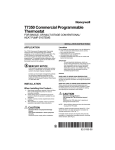
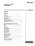
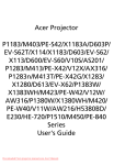
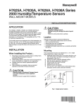
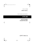
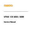
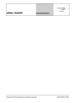
T7351 Commercial Programmable Thermostat
FOR SINGLE- OR MULTI-STAGE CONVENTIONAL/HEAT PUMP SYSTEMS
INSTALLATION INSTRUCTIONS
APPLICATION
The T7351 Commercial Programmable Thermostat
controls 24 Vac commercial single zone heating,
ventilating and air conditioning (HVAC) equipment. The
T7351 consists of a thermostat and subbase. The
thermostat includes the display and keypad for 7-day
programming. The subbase includes equipment control
connections. The subbase mounts on the wall and the
thermostat mounts to the subbase.
MERCURY NOTICE
If this control is replacing a control that contains
mercury in a sealed tube, do not place your old
control in the trash. Dispose of properly.
Contact your local waste management authority
for instructions regarding recycling and the
proper disposal of an old control. If you have
questions, call Honeywell Customer Care Center
at 1-800-468-1502.
INSTALLATION
When Installing this Product...
1.
2.
3.
4.
Read these instructions carefully. Failure to follow
them could damage the product or cause a hazardous condition.
Check ratings given in instructions and on the
product to ensure the product is suitable for your
application.
Installer must be a trained, experienced service
technician.
After installation is complete, check out product
operation as provided in these instructions.
— concealed pipes and chimneys.
— unheated (uncooled) areas such as an outside wall
behind the thermostat.
IMPORTANT
To avoid electrical interference, which can
cause erratic performances, keep wiring runs as
short as possible and do not run thermostat
wires adjacent to the line voltage electrical distribution systems. Use shielded cable. The
cable shield must be grounded only at the controlled equipment case.
Subbase
WHEN USED TO SENSE ROOM TEMPERATURE
Install the thermostat about 5 ft. (1.5m) above the floor in
an area with good air circulation at average temperature.
(See Fig. 1.)
WHEN NOT USED TO SENSE ROOM TEMPERATURE
When using the remote-mounted temperature (and
humidity) sensor(s) to sense ambient conditions, install
the thermostat in an area that is accessible for setting
and adjusting the temperature and settings.
Install the remote-mounted sensor(s) about 5 ft. (1.5m)
above the floor in an area with good air circulation at
average temperature (See Fig. 1).
If multiple remote sensors are required, they must be
arranged in a temperature averaging network consisting
of four sensors (See Fig. 2).
NOTE: Only TR21 models with no setpoint adjustment
can be used for temperature averaging.
YES
CAUTION
Electrical Shock or Equipment Damage
Hazard. Can shock individuals or short
equipment circuitry.
Disconnect power supply before installation.
NO
NO
NO
5 FEET
(1.5 METERS)
Location
Do not install the thermostat where it can be affected by:
— drafts, or dead spots behind doors and in corners.
— hot or cold air from ducts.
— radiant heat from sun or appliances.
M4823A
Fig. 1. Typical location of thermostat or
remote-mounted sensor.
Place Bar Code Here
62-0258-05
T7351 COMMERCIAL PROGRAMMABLE THERMOSTAT
Mounting Subbase
The subbase mounts horizontally.
IMPORTANT
• When using the internal temperature or humidity
sensor, the device must be mounted horizontally
(with the LCD facing upwards). Precise leveling
is not needed.
• When using remote room temperature and
humidity sensors, thermostat mounting orientation does not matter.
WIRES THROUGH WALL
MOUNTING
HOLES
Wall mounting (using standard drywall screws) is
standard. Mounting to a 2 in. by 4 in. (50.8 mm by 101.6
mm) wiring box can be accomplished:
— for a horizontal box, no extra hardware is required.
— for a vertical box, part 209651A is required.
— Mount to European standard wall box (having 2.4 in.
(60.3 mm) between mounting screws in a horizontal
line) with or without adaptive hardware.
WALL
ANCHORS
(2)
MOUNTING
SCREWS
M19608
1.
Position and level the subbase.
NOTE: A level wallplate is only for appearance.
The thermostat functions properly when
not level.
2.
3.
4.
5.
6.
7.
Use a pencil to mark the mounting holes. (See
Fig. 3).
Remove the subbase from the wall and drill two 3/
16 in. (4.8 mm) holes in the wall (if drywall) as
marked. For firmer material such as plaster or
wood, drill two 7/32 in. (5.6 mm) holes.
Gently tap anchors (provided) into the drilled holes
until flush with the wall.
Position the subbase over the holes, pulling wires
through the wiring opening.
Loosely insert the mounting screws into the holes.
Tighten mounting screws.
Fig. 3. Mounting the subbase.
Mounting Thermostat on Subbase (Fig.
4)
With the subbase installed, mount the thermostat:
1. Engage top subbase tabs into the thermostat top.
2. Swing the thermostat down.
3. Press the lower edge of the case to latch.
NOTE: To remove the thermostat from the wall, first pull
out at the bottom of the thermostat; then remove
the top.
A. ENGAGE TABS AT TOP OF THERMOSTAT AND SUBBASE OR WALLPLATE.
SUBBASE
T4
TR21
T
T
TR21
T
T3
TR21
T
T
TR21
T
T
T
B. PRESS LOWER EDGE OF CASE TO LATCH.
M29184
Fig. 2. Four TR21 Sensors providing temperature
averaging network for T7351 Thermostat.
M19609
Fig. 4. Mounting thermostat on subbase.
62-0258—05
2
T7351 COMMERCIAL PROGRAMMABLE THERMOSTAT
Wiring
Setting Temperature
Follow equipment manufacturer wiring instructions when
available. Refer to the Wiring Diagram section for typical
hookups. A letter code is located near each terminal for
identification.
Refer to Table 2 for the default temperature setpoints. To
set the Occupied and Not Occupied Heat and Cool
setpoints, simply press the Heat and Cool button under
the Occupied or Not Occupied area of the keypad. To set
the Standby Heat setpoint, press both the Occupied and
Not Occupied Heat buttons simultaneous. To set the
Standby Cool setpoint, press the Occupied Cool and Not
Occupied Heat buttons simultaneously.
IMPORTANT
All wiring must comply with local electrical codes
and ordinances.
NOTE: Maximum (and recommended) wire size is 18gauge. Do not use wire smaller than 22-gauge.
1.
2.
3.
4.
Loosen subbase terminal screws and connect system wires.
Securely tighten each terminal screw.
Push excess wire back into the hole in the wall.
Plug the hole with nonflammable insulation to prevent drafts from affecting the thermostat.
SETTINGS
Using Thermostat Keys
The thermostat keys are used to:
• set current time and day,
• program times and setpoints for heating and cooling,
• override the program temperatures,
• display present setting,
• set system and fan operation.
NOTE: See Fig. 5 for keypad information.
Setting System and Fan
System default setting is Auto. Fan default setting is On.
NOTE: Use System and Fan keys to change settings.
System Settings
— Auto: Thermostat automatically changes between
heating and cooling based on indoor temperature.
— Cool: Thermostat controls cooling.
— Off: Heating, cooling, and fan are all off.
— Heat: Thermostat controls heating.
— Em Heat: Auxiliary heat serves as first stage.
Compressor stages are locked off.
Fan Settings
— On: See Table 1.
— Auto: Fan always cycles with call for heat or cool.
— Conventional: The equipment (i.e. plenum switch)
controls fan operation in heat mode. Thermostat
controls fan operation in cool mode.
— Electric Heat: Thermostat controls fan operation in
both heat and cool modes.
NOTES: Fan operation can extend (delay Off) after the
heating/cooling turns off:
—
Heating choices are 0 or 90 seconds.
—
Cooling choices are 0 or 40 seconds.
Table 1. T7351 Intelligent™ Fan ON control logic
Call for
Heat/Cool
Occupancy
Scheduled
Period
Motion Sensor
Signal
Effective
Occupancy
Yes
No
Occupied
No Sensor Wired
Occupied
Fan On
Fan On
Occupied
Motion Sensed
Occupied
Fan On
Fan On
Occupied
No Motion Sensed
Standby
Notes
Effective Occupancy is Standby. Standby
setpoints are used and it assumes that the
Fan On Fan Offa
space is unoccupied. Fan is on only when there
is a call for heating or cooling.
Not Occupied No Sensor Wired Not Occupied Fan On Fan Offa Occupancy sensor will only be active during
scheduled Occupied periods. During scheduled
Not Occupied Motion Sensed Not Occupied Fan On Fan Offa
Not Occupied periods, the effective occupancy
Not Occupied No Motion Sensed Not Occupied Fan On Fan Offa will always be Not Occupied.
a In
heat mode, when set for conventional heat, the equipment (i.e. plenum switch) could power the fan despite the
T7350
3
62-0258—05
T7351 COMMERCIAL PROGRAMMABLE THERMOSTAT
Set Day/Time
Temperature
Occupied
HEAT
Not Occupied
COOL
HEAT
COOL
Time
System
Fan
Run
Copy
HEAT COOL
ON AUTO
Schedule
Schedule
Day
Clear
Occupied Not Occupied Start Time
Override
Temporary Temporary
Occupied Not Occupied
Day
M19610
Fig. 5. Thermostat key locations.
INSTALLER SETUP
For most applications, the thermostat factory settings do
not need to be changed. Review the factory settings in
Table 2.
A combination of key presses are required to use the
Installer Setup feature:
1. To enter the Installer Setup, press and hold both the
Run Schedule and the Copy keys until DEGREES
00 (or DEGREES 01) displays.
NOTE: Installer Setup will display WAIT and is
unavailable for 30 seconds after power up.
NOTE: When power is first applied to the thermostat, the
display will show all segments (see Fig. 6).
Table 2. Default Setpoints.
Control
Occupied
Not Occupied
Standby
Heating
70° F (21° C) 55° F (13° C)
67° F (19° C)
Cooling
75° F (24° C) 85° F (29° C)
78° F (26° C)
Temporary Standby Set Set Schedule Room
Not Occupied12 StartTime
AM
PM
System
Em Heat
%
MonTueWedThuFri SatSunHol MinsDays
Fan
OnAuto
Off Cool Auto Dehumid
2. To advance to the next Installer Setup number,
press
.
NOTE: Pressing Run/Copy again while in this
mode displays the T7351 firmware version
number.
3.
4.
5.
6.
M19611
Fig. 6. LCD display of all segments.
CAUTION
Possible Equipment Damage.
Fan must be running when system is
operating.
Heat pump and electric heat systems must be
configured correctly to prevent equipment damage
caused by the system running without the fan.
To return to a Setup item, cycle through the options.
or down
key.
To change a setting, use the up
To exit the Installer Setup, press Run Schedule.
Display prompts SAV CFG (save configuration).
a. If you want to save the new configuration, use
or down
key to change NO to
the up
YES before pressing Run Schedule.
b. If you want the configuration to remain as it was
before starting this change, ensure the
display indicates SAV CFG NO and press Run
Schedule.
NOTE: Installer Setup is automatically exited after five
minutes with no key pressed. Upon this automatic exit, all changes are lost.
Configuration
Configuration can be done with the keypad using the
Installer Setup (ISU).
Setup Using Keypad
The installer uses the Installer Setup to customize the
thermostat to specific systems
Table 3. Installer Setup.
Text
Default
Choices
Notes
DEGREES 0
0 -1
Degree Temperature Format
0: Degrees F
1: Degrees C
CLOCK
0
0-1
Clock Display Format
0: 12 hour
1: 24 hour
KEYLOCK 0
0-3
Keypad Lockout Level
0: None
1: Lockout all keys except Set Day, Set Time, Set Date, Set Holidays, Temporary
Occupied, Temporary Not Occupied, System, Fan, Up, Down and Information
2: Lockout all keys except Set Day, Set Time. Set Date, Set Holidays, Temporary
Occupied, Temporary Not Occupied, Up, Down and Information
3: Lockout all keys except Information
62-0258—05
4
T7351 COMMERCIAL PROGRAMMABLE THERMOSTAT
Table 3. Installer Setup. (Continued)
Text
Default
Choices
Notes
HEATPMP 0
0-2
Application Type Selection
0: Conventional
1: Heat Pump - Cooling (Energize O/B on call for cool)
2: Heat Pump - Heating (Energize O/B on call for heat)
COOLSTG 1
0-4
Number of Cooling Stages
0: 0 Stages of Cooling
1: 1 Stages of Cooling
2: 2 Stages of Cooling
3: 3 Stages of Cooling (Not available if Heat Pump is selected)
4: 4 Stages of Cooling (W3 will be used as 4th stage relay) (Not available if Heat
Pump is selected)
HEATSTG 1
0-3
Number of Heating Stages (Not available if Heat Pump is selected)
0: 0 Stages of Heating
1: 1 Stages of Heating
2: 2 Stages of Heating (This is the max if 4 cooling stages is selected)
3: 3 Stages of Heating
AUX STG
0
0-2
Number of Heat Pump Heating Stages (Only shown when Heat Pump is
selected)
0: 0 Aux Stages
1: 1 Aux Stages
2: 2 Aux Stages
AUX CON
0
0-3
Aux Contact Functionality
0: Time of Day
1: Economizer
2: Dehumid - Hot Gas Bypass
3: Simple Dehumid
WALLMOD 0
0-3
Remote Room Sensor Selection
0: Local sensor only
1: TR21/TR24 and T7770A/D (Remote Sensor, No Remote Setpoint, Bypass 0)
2: TR22/TR23 and T7770B/C (Remote Sensor, Remote Setpoint, Bypass 0)
3: T7771 (Remote sensor, Remote Setpoint, Bypass 1)
(Bypass 0 means that by pressing the override button the thermostat goes from
unoccupied to occupied and the LED will light up and the temporary occupied
timer will begin. If the button is pressed again, the timer will restart.)
(Bypass 1 means that by pressing the override button a second time the
thermostat can return to the unoccupied period.)
OATSENS 0
0-1
Outdoor Air Sensor Selection
0: None
1: Remote Outdoor Air Sensor
DATSENS 0
0-1
Discharge Air Sensor Selection
0: None
1: Remote Discharge Air Sensor
HUMSENS 0
0-2
Room Humidity Sensor selection
0: None
1: On Board Sensor
2: Remote Sensor
OCCSENS 0
0-1
Occupancy Sensor Selection
0: None
1: Remote Occ Sensor
FAN HT
0
0-1
Fan Operation on Heat
0: Conventional (Equipment controls Fan)
1: Electric (Thermostat turns on Fan with call for Heat)
XFAN HT
YES
YES or NO
Extended Fan on Heat
NO: None
YES: 90 seconds
XFAN CL
NO
YES or NO
Extended Fan on Cool
NO: None
YES: 40 seconds
STRTDEL
0
0 - 15
Sequential Start Delay
0 to 150 seconds in 10 second increments
YES or NO
Advanced Settings
NO: Hide
YES: Show
ADVANCE NO
5
62-0258—05
T7351 COMMERCIAL PROGRAMMABLE THERMOSTAT
Table 3. Installer Setup. (Continued)
Text
Default
Choices
Notes
TMP LIM
3
0-5
Temporary Setpoint Adjustment
0: 0 Deg. F
1: 1 Deg. F
2: 2 Deg. F
3: 3 Deg. F
4: 4 Deg. F
5: 5 Deg. F
TMP OCC
3
1-8
Temporary Occupied Duration
1 to 8 hours
TMP CAL
0
-4 - 3
Temporary Display Adjustment
0 - 3 = 0 to 3 DDF
4 - 7 = -4 to -1 DDF
45° - 99° F
(7° - 37° C)
Min Cool Setpoint
MINCOOL 45° F
(7° C)
MAXHEAT 90° F 40° - 90° F
(32° C) (4° - 32°)
Max Heat Setpoint
HEATLCK
NO
Heating Lockout (Only displayed if Outdoor Air Sensor is selected)
NO: None
YES: Enabled
HTLCKSP
70° F -40° - 120 ° F
(21° C) (-40° - 49° F)
YES or NO
Heating Lockout Temperature
(Display only if Remote Outdoor Air Sensor is configured)
COOLLCK NO
YES or NO
Cooling Lockout (Only displayed if Outdoor Air Sensor is Selected)
NO: None
YES: Enabled
CLLCKSP
35° F
(2° C)
-40° - 120° F
(-40° - 49° C)
Cooling Lockout Temperature
(Display only if Remote Outdoor Air Sensor is configured)
DAT LL
NO
YES or NO
Discharge Low Limit (Only displayed if Discharge Air Sensor is Selected)
NO: None
YES: Enabled
DATLLSP
45° F
(7° C)
35° - 60° F
(2° - 16° C)
Discharge Low Temp Limit
(Display only if Discharge Sensor is configured)
DAT HL
NO
YES or NO
Discharge High Limit (Only displayed if Discharge Air Sensor is Selected)
NO: None
YES: Enabled
DATHLSP
110° F 65° - 140° F
(43° C) (18° - 60° C)
DEHUMID 0
0-5
Discharge High Temperature Limit
(Display only if Discharge Sensor is configured)
Dehumidification
0: None
1: MinOn Time
2: Reset Temp Setpoint
3: Reset w/ MinOn
4: Reheat
5: Reheat w/ Min On
DEH MIN
5
5 - 15
Dehumidify Minutes On
DEH TMP
2
1-5
Dehumidify Temp Reset
MINHTRT
5
0 - 20 DDF/HR
Minimum Heat Recovery Ramp Rate
MAXHTRT 8
0 - 20 DDF/HR
Maximum Heat Recovery Ramp Rate (Only Displayed if Outdoor Sensor is
Selected)
MINHTOA
-20° - 120° F
(-29° - 49° C)
Minimum Heat Outdoor Air Temperature (Only Displayed if Outdoor Sensor is
Selected)
MAXHTOA 40° F
(4° C)
-20° - 120° F
(-29° - 49° C)
Maximum Heat Outdoor Air Temperature (Only Displayed if Outdoor Sensor is
Selected)
MINCLRT
3
0 - 20 DDF/HR
Minimum Cool Recovery Ramp Rate
MAXCLRT 6
0 - 20 DDF/HR
Maximum Cool Recovery Ramp Rate (Only Displayed if Outdoor Sensor is
Selected)
MINCLOA
0° F
(-18°
C)
90° F -20° - 120° F
(32° C) (-29° - 49° C)
Minimum Cool Outdoor Air Temperature (Only Displayed if Outdoor Sensor is
Selected)
MAXCLOA 70° F -20° - 120° F
(21° C) (-29° - 49° C)
Maximum Cool Outdoor Air Temperature (Only Displayed if Outdoor Sensor is
Selected)
62-0258—05
6
T7351 COMMERCIAL PROGRAMMABLE THERMOSTAT
Table 3. Installer Setup. (Continued)
Text
Default
Choices
Notes
(DayLight Savings options only display when Date is valid)
DSTMON1 3
0 - 12
DLS Spring Month
DSTDAY1
0 - 31, 32 - 74
DLS Spring Day
0 - 31 = Day of Month
32 = Last Day of Month
33 = First Sunday
etc…
DSTMON2 11
0 - 12
DLS Fall Month
DSTDAY2
33
0 - 31, 32 - 74
DLS Fall Day
0 - 31 = Day of Month
32 = Last Day of Month
33 = First Sunday
etc…
HT RESP
1
0-3
0: Standard - 3 cph
1: Medium - 6 cph
2: Fast - 9 cph
3: Super Fast - 20 cph
CL RESP
0
0-1
0: Standard - 3 cph
1: Fast - 4 cph
40
Holidays and 365 - Day Clock
The T7351can be configured to schedule up to 10
separate holidays, each with a duration of up to 99 days.
To enable this function, the user must set the date:
1.
2.
3.
4.
5.
Press Set Day and Set Time keys simultaneously.
Use the Up/Down keys to set the date to YES, then
press the
key.
Use the Up/Down keys to set the month, then press
the
key.
Use the Up/Down keys to set the day, then press
the
key (See Table 4 for valid day choices).
Use the Up/Down keys to set the year, then press
the
key.
Holidays can be set in the following manner:
1. Press the “Temporary Occupied” and Temporary
Not Occupied” keys simultaneously.
2. The month (MON) of the first holiday is then displayed (00 means the holiday is ignored).
3. Use the Up/Down keys to set the month, then press
the
key.
4. Use the Up/Down keys to set the day, then press
the
key (see Table 4 for valid day choices).
5. Use the Up/Down keys to set the duration.
The first holiday is now set and pressing the
key will
take you to programming the second holiday (denoted by
the number 2 on the screen).
Table 4. Valid Day Values.
Value
Description
1 to 31 Day of month
Value
42
Description
Value
Description
Value
Description
Second Tuesday
53
Third Saturday
64
Fifth Wednesday
32
Last Day of Month 43
Second Wednesday
54
Fourth Sunday
65
Fifth Thursday
33
First Sunday
44
Second Thursday
55
Fourth Monday
66
Fifth Friday
34
First Monday
45
Second Friday
56
Fourth Tuesday
67
35
First Tuesday
46
Second Saturday
57
Fourth Wednesday 68
Fifth Saturday
Last Sunday
36
First Wednesday
47
Third Sunday
58
Fourth Thursday
69
Last Monday
37
First Thursday
48
Third Monday
59
Fourth Friday
70
Last Tuesday
38
First Friday
49
Third Tuesday
60
Fourth Saturday
71
Last Wednesday
39
First Saturday
50
Third Wednesday
61
Fifth Sunday
72
Last Thursday
40
Second Sunday
51
Third Thursday
62
Fifth Monday
73
Last Friday
41
Second Monday
52
Third Friday
63
Fifth Tuesday
74
Last Saturday
Table 5. T7351 Key Function Summary.
Grouping
Information
Button
Definition
Down Arrow
Lowers setpoint, day, or time. When setting times or temperatures, hold key
down to continuously decrease value. Also can make temporary change in
temperature setpoint.
Information
Obtains information (where humidity “high-limit” can be set), cycles through
setup options.
Up Arrow
Raises setpoint, day, or time. When setting times or temperatures, hold key
down to continuously increase value. Also can make temporary change in
temperature setpoint.
7
62-0258—05
T7351 COMMERCIAL PROGRAMMABLE THERMOSTAT
Table 5. T7351 Key Function Summary. (Continued)
Grouping
Temperature
Set
Override
Schedule
a
Button
Definition
Occupied
Heat
Sets Occupied Heat setpoint.
Occupied
Cool
Sets Occupied Cool setpoint.
Not
Occupied
Heat
Sets Not Occupied Heat setpoint.
Not
Occupied
Cool
Sets Not Occupied Cool setpoint.
Day
Sets day of week. Tapping key with 'Set Value' segment on increases current
day (same effect as Up Arrow key).
Time
Sets time. Tapping key with “Set Value” segment on increases time in one
hour increments.
Temporary
Occupied
Temporary occupied setting for length of time defined by installer. User can
modify setpoints.
Temporary Not
Occupied
Sets holiday length. User selects number of days (“0”-”99”), or “---” for
continuous override.
Day
Selects day schedule to modify. (Used also with copy key.)
Occupied
Selects occupied event start times for specified day. Repeatedly press this
key to toggle between two occupied events.
Not Occupied
Selects not occupied event start times for specified day. Repeatedly press
this key to toggle between two not occupied events.
Clear Start Time
Clears start time for specified period and day.
Copy
Copies schedule from one day to another.
System
Selects System Mode. Toggles through Em Heat, Heat, Off, Cool, and Auto.
Fan
Selects fan operation mode. Toggles between On and Auto.a
Run Schedule
Resumes running schedule (cancels Temporary Occupied action, Holiday,
and/or Temporary setpoint changes.)
On: Continuous fan operation during occupied periods. During not occupied periods and in standby mode when no
motion is sensed, fan cycles with call for heat or cool.
Auto: Fan cycles with call for heat or cool during all periods. (See Product Data Sheet, form 63-2605, for more details).
NOTES: The display returns to default screen after pressing Run Schedule (or after a period of time without keypress):
—
ten seconds: when returning from temporary setpoint changes, info screen, temp occ, and temp not occ.
—
one minute: when returning from setting clock/day.
—
ten minutes: when returning from System Checkout.
—
five minutes: when returning from all other modes.
Special Functions
Restore Factory Configuration (Run/
Clear)
IMPORTANT
This operation erases current configuration and
restores factory defaults for all configuration,
parameters, setpoints and schedules. To regain
the old requires device reconfiguration.
1.
2.
Press both Run Schedule and Clear Start Time.
The display gives the option to revert to FAC CFG.
or
a. To restore the factory defaults, press up
until the display indicates YES.
down
b. To cancel this option, ensure the display
indicates NO.
62-0258—05
3. Press Run Schedule.
Get Factory Schedule (Info/Clear)
Performing this operation reverts the schedules to the
factory defaults:
1. Press both Info and Clear Start Time.
2. The display gives the option to revert to FAC SCH.
or
a. To restore the factory schedule, press up
until the display indicates YES.
down
b. To cancel this option, ensure display indicates
NO.
3. Press Run Schedule.
8
T7351 COMMERCIAL PROGRAMMABLE THERMOSTAT
Test Mode (Occupied/Not Occupied/
Schedule Day)
CAUTION
Possible Equipment Damage.
Equipment damage can result if compressor is
cycled too quickly.
The minimum off time for compressors is
bypassed during Test Mode. Equipment damage
can occur if the compressor is cycled too quickly.
Use the Test Mode to check the thermostat configurations
and operation. To start the system test:
1. Press Schedule Day, Occupied and Not Occupied
simultaneously.
2. The display gives the option to TEST.
or down
a. To enter test mode, press up
until the display indicates IN TEST.
b. To cancel this option, ensure display indicates
NO TEST.
3. Press Run Schedule.
NOTES:
—
—
To verify whether or not the system test is still
active, repeat the above process.
The system test times out after ten minutes
with no key pressed.
Save User Schedule (Info/Copy)
NOTES:
—
—
These methods operate only during cooling.
Selecting both Reheat and Reset options can
cause frequent setpoint adjustments. This
selection is not recommended.
Min. ON Time
Dehumidifies by increasing the compressor minimum on
time (normally 3 minutes) by a programmable amount.
This is useful with oversized systems in that it forces the
coils to cool to a point where dehumidification can occur.
NOTES:
—
—
—
Can force wider temperature swings by cooling when setpoint control does not require it.
The minimum on time can be set within the
range of 5 to 15 minutes.
Hysteresis and a minimum timer are used to
ensure this behavior does not change with
every equipment cycle.
Reheat
Dehumidifies by operating cooling during typical off time.
The T7351 maintains the proper setpoint by running the
heat at the same time.
IMPORTANT
At times during Reheat dehumidification, the
T7351 operates heating and the cooling simultaneously. This is normal.
Performing this operation saves the current schedule
(including holidays) to memory, overwriting the old saved
schedule:
1. Press both Info and Copy.
2. The display gives the option to revert to SAV SHD.
or
a. To save the current schedule, press up
until the display indicates YES.
down
b. To cancel this option, ensure display indicates
NO.
3. Press Run Schedule.
NOTES:
—
Get User Schedule (Info/Run)
Though this may not technically reduce relative humidity
in the room, it reduces the dew point to provide the
customer with a sense of comfort due to a lower
temperature setting in the room.
Getting the user schedule restores the schedule
(including holidays) from saved memory, overwriting the
schedule currently in use:
1. Press both Run Schedule and Info.
2. The display gives the option to GET SHD.
or
a. To retrieve the saved schedule, press up
until the display indicates YES.
down
b. To cancel this option, ensure display indicates
NO.
3. Press Run Schedule
DEHUMIDIFICATION
There are five methods through which the T7351 can
control for dehumidification. Three of them modify the
control algorithm, thus providing limited dehumidification
through cooling. The other two use the auxiliary output to
control another device.
NOTE: The dehumidification high limit can be set within
the range of 10 to 90 percent relative humidity.
Control Through Cooling
Configure using some combination of the following:
— Minimum On.
— Reheat.
— Reset.
—
The heat stage never energizes during
Reheat if more than one cool stage is on.
Reheat mode cannot occur during heating.
Reset Temp SetPt
The room temperature set point resets to a specified
number of degrees below the actual set point when room
relative humidity (RH) rises above humidity high limit set
point.
As long as RH stays above humidity high limit set point,
this set point is maintained.
NOTE: Hysteresis and a minimum timer prevent the set
point from short interval alternation (between
standard and reset set points).
Options Utilizing Auxiliary Output
There are two dehumidification options that utilize the
auxiliary output. They are:
— Simple Dehumidification.
— Hot Gas Bypass Dehumidification.
Simple Dehumid(ification)
The auxiliary output:
— Energizes when RH rises above humidity high limit.
— De-energizes when RH drops below humidity high
limit.
NOTES:
—
—
9
Hysteresis and a minimum timer prevent
short cycling of this output.
Unlike Dehumid Hot Gas BP the relay
remains energized during calls for multiple
cooling stages.
62-0258—05
T7351 COMMERCIAL PROGRAMMABLE THERMOSTAT
Dehumid Hot Gas BP
The auxiliary output operates as shown in Table 6.
Table 6. Hot Gas Bypass Dehumidification Logic.
Humidity
Cooling Stages Active Auxiliary Output
High
more than one
De-energized
High
one or less
Energized
Low
more than one
De-energized
Low
one or less
De-energized
62-0258—05
Auxiliary output during call for multiple cooling stages for
two reasons:
1. This method assumes that the cooling provides
dehumidification.
2. Multiple cooling stages probably provide necessary
dehumidification.
3. Hysteresis and a minimum timer prevent short
cycling of this output.
10
T7351 COMMERCIAL PROGRAMMABLE THERMOSTAT
WIRING DIAGRAMS
4
3
5
6
OUTDOOR
AIR
SENSOR
BYPASS
2
LED
SENSOR
1
SET PT
GND
TR23-H REMOTE SENSOR
7 8 9 10 11 12
COMPRESSOR
CONTACTOR 2
AUX HEAT
STAGE 1
DISCHARGE
AIR SENSOR
SUBBASE
T5
T6
T7
T4
T3
OS
OS
M
M
AS
AS
X
RH
W2
W1
Y2
Y1
G
4
HS
HC
HP
RC
AUX
O/B
2
HUMIDITY
SENSOR
CHANGEOVER
MOTION
SENSOR
COMPRESSOR
CONTACTOR 1
3
L2
1
FAN
RELAY
L2
1
L1
(HOT)
ECONOMIZER
L1
(HOT)
HEATING
TRANSFORMER
COOLING
TRANSFORMER
1
POWER SUPPLY. PROVIDE DISCONNECT MEANS AND OVERLOAD PROTECTION AS REQUIRED.
2
WHEN INSTALLED ON A SYSTEM WITH TWO TRANSFORMERS, REMOVE THE FACTORY-INSTALLED JUMPER.
3
USE ECONOMIZER INSTRUCTIONS FOR INSTALLATION DIRECTIONS.
4
WHEN USING THE TR23-H FOR HUMIDITY SENSING, THERE IS NO NEED TO WIRE THE HC TERMINAL
BECAUSE THE T3 TERMINAL IS INTERNALLY TIED TO HC, WHICH IS ALSO TIED TO TERMINAL 1
COMMON AT THE SENSOR.
M29323
Fig. 7. Typical hookup of T7351F2010 in two-stage heat and two-stage cool heat pump system with two
transformers.
3
4
5
6
OUTDOOR
AIR
SENSOR
BYPASS
2
LED
SENSOR
1
SET PT
GND
TR23-H REMOTE SENSOR
7 8 9 10 11 12
HEAT
RELAY 2
DISCHARGE
AIR
SENSOR
COMPRESSOR
CONTACTOR 4
COMPRESSOR
CONTACTOR 2
SUBBASE
T5
T6
T7
T4
HS
HC
T3
OS
OS
AS
AS
HP
M
M
X
RH
W3/Y4 Y3
RC
AUX
W1
W2
Y2
Y1
G
COMPRESSOR
CONTACTOR 3
5
HUMIDITY
SENSOR
3
MOTION
SENSOR
HEAT
RELAY 1
4
1
2
L2
FAN
RELAY
COMPRESSOR
CONTACTOR 1
ECONOMIZER
L1
(HOT)
1
POWER SUPPLY. PROVIDE DISCONNECT MEANS AND OVERLOAD PROTECTION AS REQUIRED.
2
ENSURE TRANSFORMER IS SIZED TO HANDLE THE LOAD.
3
HEAT/COOL SYSTEMS WITH ONE TRANSFORMER REQUIRE THE FACTORY-INSTALLED JUMPER.
4
USE ECONOMIZER INSTRUCTIONS FOR INSTALLATION DIRECTIONS.
5
WHEN USING THE TR23-H FOR HUMIDITY SENSING THERE IS NO NEED TO WIRE HC TERMINAL
BECAUSE THE T3 TERMINAL IS INTERNALLY TIED TO HC, WHICH IS ALSO TIED TO TERMINAL 1
COMMON AT THE SENSOR.
M29254
Fig. 8. Typical hookup of T7351F2010 in two-stage heat and four-stage cool conventional system.
11
62-0258—05
T7351 COMMERCIAL PROGRAMMABLE THERMOSTAT
3
4
5
6
OUTDOOR
AIR
SENSOR
BYPASS
2
SET PT
SENSOR
1
LED
GND
TR23-H REMOTE SENSOR
7 8 9 10 11 12
COMPRESSOR
CONTACTOR 2
DISCHARGE
AIR
SENSOR
HEAT
RELAY 3
HEAT
RELAY 2
SUBBASE
T5
T6
T7
T4
T3
OS
OS
AS
AS
HP
M
M
X
RH
W3/Y4 Y3
W2
Y2
Y1
G
5
HS
HC
RC
AUX
W1
COMPRESSOR
CONTACTOR 3
HUMIDITY
SENSOR
3
MOTION
SENSOR
HEAT
RELAY 1
4
1
2
L2
FAN
RELAY
COMPRESSOR
CONTACTOR 1
ECONOMIZER
L1
(HOT)
1
POWER SUPPLY. PROVIDE DISCONNECT MEANS AND OVERLOAD PROTECTION AS REQUIRED.
2
ENSURE TRANSFORMER IS SIZED TO HANDLE THE LOAD.
3
HEAT/COOL SYSTEMS WITH ONE TRANSFORMER REQUIRE THE FACTORY-INSTALLED JUMPER.
4
USE ECONOMIZER INSTRUCTIONS FOR INSTALLATION DIRECTIONS.
5
WHEN USING THE TR23-H FOR HUMIDITY SENSING THERE IS NO NEED TO WIRE HC TERMINAL
BECAUSE THE T3 TERMINAL IS INTERNALLY TIED TO HC, WHICH IS ALSO TIED TO TERMINAL 1
COMMON AT THE SENSOR.
M29255
Fig. 9. Typical hookup of T7351F2010 in three-stage heat and three-stage cool conventional system
with one transformer.
TROUBLESHOOTING GUIDE (TABLE 7)
Table 7. Troubleshooting Information.
Symptom
Possible Cause
Action
Display will not
come on.
Thermostat is not being
powered.
Check that X terminal is connected to the system transformer.
Check for 24 Vac between X and RH terminals.
If missing 24 Vac:
• Check if circuit breaker is tripped; if so, reset circuit breaker.
• Check if system fuse is blown; if so, replace fuse.
• Check if the HVAC equipment power switch is in the Off position; if
so, set to the On position.
• Check wiring between thermostat and HVAC equipment. Replace
broken wires and tighten loose connections.
If 24 Vac is present, proceed with troubleshooting.
Temperature
display is
incorrect.
Thermostat is configured
for °F or °C display.
Press both Run Schedule and Copy, then reconfigure the display.
Bad thermostat location.
Relocate the thermostat.
Display shows three
dashes and a degree sign
(all systems shut down).
T7351 is set for remote sensing and sensor is missing or circuit is
either open or shorted.
Temperature
settings will not
change.
(Example:
Cannot set
heating higher or
cooling lower.)
Room
temperature is
out of control.
62-0258—05
Upper or lower temperature Check the temperature setpoints:
limits were reached.
• Heating limits are 40 to 90°F (7 to 31°C)
• Cooling limits are 45 to 99°F (9 to 37°C)
Occupied setpoint
temperature range stops
were configured.
Check setpoint stops. If necessary, reconfigure the stop(s).
Keypad is locked. When a
locked key is pressed,
LOCKED appears
momentarily on the LCD.
Press both Run Schedule and Copy, then change keypad lock level.
Remote temperature
sensing is not working.
Check all remote sensors.
12
T7351 COMMERCIAL PROGRAMMABLE THERMOSTAT
Table 7. Troubleshooting Information. (Continued)
Symptom
Heat will not
come on.
Cooling will not
come on.
System indicator
(flame: heat,
snowflake: cool)
is displayed, but
no warm or cool
air is coming
from the
registers.
Possible Cause
Action
No power to the thermostat. Check that X terminal is connected to the system transformer.
Check for 24 Vac between X and RH terminals.
If missing 24 Vac:
• Check if circuit breaker is tripped; if so, reset circuit breaker.
• Check if system fuse is blown; if so, replace fuse.
• Check if the HVAC equipment power switch is in the Off position; if
so, set to the On position.
• Check wiring between thermostat and HVAC equipment. Replace
broken wires and tighten loose connections.
If 24 Vac is present, proceed with troubleshooting.
Thermostat minimum off
time is activated.
• Wait up to five minutes for the system to respond.
• Configure heating response.
System selection is set to
Off or Cool.
Set system selection to Heat or Auto.
No power to the thermostat. Check that X terminal is connected to the system transformer.
Check for 24 Vac between X and RH terminals.
If missing 24 Vac:
• Check if circuit breaker is tripped; if so, reset circuit breaker.
• Check if system fuse is blown; if so, replace fuse.
• Check if the HVAC equipment power switch is in the Off position; if
so, set to the On position.
• Check wiring between thermostat and HVAC equipment. Replace
broken wires and tighten loose connections.
If 24 Vac is present, proceed with troubleshooting.
Thermostat minimum off
time is activated.
• Wait up to five minutes for the system to respond.
• Configure cooling response.
System selection is set to
Off or Heat.
Set system selection to Cool or Auto.
The call for heat or cool is
not yet given.
Check if any stage indicators (dots next to the system indicator) are
displayed. With no display of stage indicators, no call for cool/heat is
yet given.
Conventional heating
Wait one minute after seeing the on indicator and then check the
equipment turns the fan on registers.
only after the furnace has
warmed to a setpoint.
Heating or cooling
Verify operation of heating or cooling equipment in self-test.
equipment is not operating.
13
62-0258—05
T7351 COMMERCIAL PROGRAMMABLE THERMOSTAT
62-0258—05
14
T7351 COMMERCIAL PROGRAMMABLE THERMOSTAT
15
62-0258—05
T7351 COMMERCIAL PROGRAMMABLE THERMOSTAT
Automation and Control Solutions
Honeywell International Inc.
1985 Douglas Drive North
Golden Valley, MN 55422
Honeywell Limited-Honeywell Limitée
35 Dynamic Drive
Toronto, Ontario M1V 4Z9
customer.honeywell.com
® U.S. Registered Trademark
© 2010 Honeywell International Inc.
62-0258—05 M.S. Rev. 09-10
Printed in U.S.A.