1
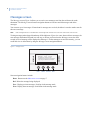
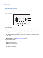
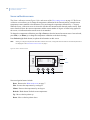
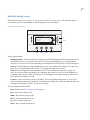
SmartCommand Thermostat
Installation Manual
g
Copyright
Copyright © 2007 GE Security. All rights reserved.
This document may not be copied in whole or in part or otherwise reproduced without prior
written consent from GE Security except where specifically permitted under US and
international copyright law.
Document number/revision: 1060018A (July 2007).
Disclaimer
The information in this document is subject to change without notice. GE Security (“GE”)
assumes no responsibility for inaccuracies or omissions and specifically disclaims any
liabilities, losses, or risks, personal or otherwise, incurred as a consequence, directly or
indirectly, of the use or application of any of the contents of this document. For the latest
documentation, contact your local supplier or visit us online at www.gesecurity.com.
This publication may contain examples of screen captures and reports used in daily operations.
Examples may include fictitious names of individuals and companies. Any similarity to names
and addresses of actual businesses or persons is entirely coincidental.
Trademarks and patents
GE and the GE monogram are registered trademarks of General Electric Company.
Other trade names used in this document may be trademarks or registered trademarks of the
manufacturers or vendors of the respective products.
Intended use
Use this product only for the purpose it was designed for; refer to the data sheet and user
documentation. For the latest product information, contact your local supplier or visit us online
at www.gesecurity.com.
FCC compliance
This equipment has been tested and found to comply with the limits for a Class B digital device,
pursuant to part 15 of the FCC rules. These limits are designed to provide reasonable protection
against harmful interference when the equipment is operated in a residential environment. This
equipment generates, uses, and can radiate radio frequency energy and, if not installed and
used in accordance with the instruction manual, may cause harmful interference to radio
communications.
Changes or modifications not expressly approved by the party responsible for compliance
could void the user’s authority to operate the equipment.
EMC directive
The European Union directive on electromagnetic compatibility (2004/108/EC) requires nonEuropean manufacturers to designate an authorized representative in the Community.
Our European representative is GE Security, Kelvinstraat 7, 6003 DH Weert, Nederland.
The European directive Waste Electrical and Electronic Equipment (WEEE) aims to minimize the
impact of electrical and electronic equipment waste on the environment and human health. For
proper treatment, recovery, and recycling, return the equipment marked with this symbol to
your local supplier upon the purchase of equivalent new equipment, or dispose of it in
designated collection points. For more information, visit www.recyclethis.com.
iii
Contents
Preface . . . . . . . . . . . . . . . . . . . . . . . . . . . . . . . . . . . . . . . . . . . . . . . . . . . . . . . . . . . . . . . . . . . . . . . . . . . . . . . . . . . . . . . . . 1
Conventions used in this document. . . . . . . . . . . . . . . . . . . . . . . . . . . . . . . . . . . . . . . . . . . . . . . . . . . . . . . . . . . . . . . . . . . 1
Safety terms and symbols . . . . . . . . . . . . . . . . . . . . . . . . . . . . . . . . . . . . . . . . . . . . . . . . . . . . . . . . . . . . . . . . . . . . . . . . . . . 1
Product overview. . . . . . . . . . . . . . . . . . . . . . . . . . . . . . . . . . . . . . . . . . . . . . . . . . . . . . . . . . . . . . . . . . . . . . . . . . . . . . . . 2
Wall display unit (WDU) . . . . . . . . . . . . . . . . . . . . . . . . . . . . . . . . . . . . . . . . . . . . . . . . . . . . . . . . . . . . . . . . . . . . . . . . . . . . . . 2
Thermostat control screen . . . . . . . . . . . . . . . . . . . . . . . . . . . . . . . . . . . . . . . . . . . . . . . . . . . . . . . . . . . . . . . . . . . . . . . 4
Temperature display. . . . . . . . . . . . . . . . . . . . . . . . . . . . . . . . . . . . . . . . . . . . . . . . . . . . . . . . . . . . . . . . . . . . . . . . . . . . . . . . . 4
Setpoint display . . . . . . . . . . . . . . . . . . . . . . . . . . . . . . . . . . . . . . . . . . . . . . . . . . . . . . . . . . . . . . . . . . . . . . . . . . . . . . . . . . . . . 4
Clock display . . . . . . . . . . . . . . . . . . . . . . . . . . . . . . . . . . . . . . . . . . . . . . . . . . . . . . . . . . . . . . . . . . . . . . . . . . . . . . . . . . . . . . . . 4
Up and down buttons. . . . . . . . . . . . . . . . . . . . . . . . . . . . . . . . . . . . . . . . . . . . . . . . . . . . . . . . . . . . . . . . . . . . . . . . . . . . . . . . 5
Menu button . . . . . . . . . . . . . . . . . . . . . . . . . . . . . . . . . . . . . . . . . . . . . . . . . . . . . . . . . . . . . . . . . . . . . . . . . . . . . . . . . . . . . . . . 5
Mode button . . . . . . . . . . . . . . . . . . . . . . . . . . . . . . . . . . . . . . . . . . . . . . . . . . . . . . . . . . . . . . . . . . . . . . . . . . . . . . . . . . . . . . . . 5
Fan button . . . . . . . . . . . . . . . . . . . . . . . . . . . . . . . . . . . . . . . . . . . . . . . . . . . . . . . . . . . . . . . . . . . . . . . . . . . . . . . . . . . . . . . . . . 5
Run/Hold button. . . . . . . . . . . . . . . . . . . . . . . . . . . . . . . . . . . . . . . . . . . . . . . . . . . . . . . . . . . . . . . . . . . . . . . . . . . . . . . . . . . . . 6
LED display. . . . . . . . . . . . . . . . . . . . . . . . . . . . . . . . . . . . . . . . . . . . . . . . . . . . . . . . . . . . . . . . . . . . . . . . . . . . . . . . . . . . . . . . . . 6
Communication error display . . . . . . . . . . . . . . . . . . . . . . . . . . . . . . . . . . . . . . . . . . . . . . . . . . . . . . . . . . . . . . . . . . . . . . . . 6
Main menu screen . . . . . . . . . . . . . . . . . . . . . . . . . . . . . . . . . . . . . . . . . . . . . . . . . . . . . . . . . . . . . . . . . . . . . . . . . . . . . . . 7
Messages screen . . . . . . . . . . . . . . . . . . . . . . . . . . . . . . . . . . . . . . . . . . . . . . . . . . . . . . . . . . . . . . . . . . . . . . . . . . . . . . . . 8
Schedule setup screen . . . . . . . . . . . . . . . . . . . . . . . . . . . . . . . . . . . . . . . . . . . . . . . . . . . . . . . . . . . . . . . . . . . . . . . . . . . 9
Heat and cool schedule screen . . . . . . . . . . . . . . . . . . . . . . . . . . . . . . . . . . . . . . . . . . . . . . . . . . . . . . . . . . . . . . . . . . . . . .10
Copy schedule screen . . . . . . . . . . . . . . . . . . . . . . . . . . . . . . . . . . . . . . . . . . . . . . . . . . . . . . . . . . . . . . . . . . . . . . . . . . . . . .11
User settings screen . . . . . . . . . . . . . . . . . . . . . . . . . . . . . . . . . . . . . . . . . . . . . . . . . . . . . . . . . . . . . . . . . . . . . . . . . . . . 12
Set clock screen . . . . . . . . . . . . . . . . . . . . . . . . . . . . . . . . . . . . . . . . . . . . . . . . . . . . . . . . . . . . . . . . . . . . . . . . . . . . . . . . . . . .13
Sensor calibration screen . . . . . . . . . . . . . . . . . . . . . . . . . . . . . . . . . . . . . . . . . . . . . . . . . . . . . . . . . . . . . . . . . . . . . . . . . . .14
Backlight display screen . . . . . . . . . . . . . . . . . . . . . . . . . . . . . . . . . . . . . . . . . . . . . . . . . . . . . . . . . . . . . . . . . . . . . . . . . . . .15
Thermostat information screen . . . . . . . . . . . . . . . . . . . . . . . . . . . . . . . . . . . . . . . . . . . . . . . . . . . . . . . . . . . . . . . . . . 16
Installer settings screen . . . . . . . . . . . . . . . . . . . . . . . . . . . . . . . . . . . . . . . . . . . . . . . . . . . . . . . . . . . . . . . . . . . . . . . . 17
Installation overview . . . . . . . . . . . . . . . . . . . . . . . . . . . . . . . . . . . . . . . . . . . . . . . . . . . . . . . . . . . . . . . . . . . . . . . . . . . 20
Freeze protection . . . . . . . . . . . . . . . . . . . . . . . . . . . . . . . . . . . . . . . . . . . . . . . . . . . . . . . . . . . . . . . . . . . . . . . . . . . . . . . . . . .21
Wall display unit installation . . . . . . . . . . . . . . . . . . . . . . . . . . . . . . . . . . . . . . . . . . . . . . . . . . . . . . . . . . . . . . . . . . . . 22
Mounting. . . . . . . . . . . . . . . . . . . . . . . . . . . . . . . . . . . . . . . . . . . . . . . . . . . . . . . . . . . . . . . . . . . . . . . . . . . . . . . . . . . . . . . . . . .22
Wiring. . . . . . . . . . . . . . . . . . . . . . . . . . . . . . . . . . . . . . . . . . . . . . . . . . . . . . . . . . . . . . . . . . . . . . . . . . . . . . . . . . . . . . . . . . . . . .22
Control unit installation. . . . . . . . . . . . . . . . . . . . . . . . . . . . . . . . . . . . . . . . . . . . . . . . . . . . . . . . . . . . . . . . . . . . . . . . . 23
Control unit to WDU wiring . . . . . . . . . . . . . . . . . . . . . . . . . . . . . . . . . . . . . . . . . . . . . . . . . . . . . . . . . . . . . . . . . . . . . . . . . .23
Control unit to HVAC wiring . . . . . . . . . . . . . . . . . . . . . . . . . . . . . . . . . . . . . . . . . . . . . . . . . . . . . . . . . . . . . . . . . . . . . . . . .23
Retrofit wiring . . . . . . . . . . . . . . . . . . . . . . . . . . . . . . . . . . . . . . . . . . . . . . . . . . . . . . . . . . . . . . . . . . . . . . . . . . . . . . . . . . . . . .23
HVAC system wiring. . . . . . . . . . . . . . . . . . . . . . . . . . . . . . . . . . . . . . . . . . . . . . . . . . . . . . . . . . . . . . . . . . . . . . . . . . . . 24
Standard HVAC system wiring. . . . . . . . . . . . . . . . . . . . . . . . . . . . . . . . . . . . . . . . . . . . . . . . . . . . . . . . . . . . . . . . . . . . . . .24
Heat pump HVAC system wiring. . . . . . . . . . . . . . . . . . . . . . . . . . . . . . . . . . . . . . . . . . . . . . . . . . . . . . . . . . . . . . . . . . . . .26
Control unit connection . . . . . . . . . . . . . . . . . . . . . . . . . . . . . . . . . . . . . . . . . . . . . . . . . . . . . . . . . . . . . . . . . . . . . . . . . . . . .28
Serial communication. . . . . . . . . . . . . . . . . . . . . . . . . . . . . . . . . . . . . . . . . . . . . . . . . . . . . . . . . . . . . . . . . . . . . . . . . . . . . . .29
System checklist . . . . . . . . . . . . . . . . . . . . . . . . . . . . . . . . . . . . . . . . . . . . . . . . . . . . . . . . . . . . . . . . . . . . . . . . . . . . . . . 31
Thermostat bench test . . . . . . . . . . . . . . . . . . . . . . . . . . . . . . . . . . . . . . . . . . . . . . . . . . . . . . . . . . . . . . . . . . . . . . . . . . . . . .31
iv
SmartCommand Thermostat
Installation Manual
Serial communication test . . . . . . . . . . . . . . . . . . . . . . . . . . . . . . . . . . . . . . . . . . . . . . . . . . . . . . . . . . . . . . . . . . . . . . . . . .32
HVAC system testing . . . . . . . . . . . . . . . . . . . . . . . . . . . . . . . . . . . . . . . . . . . . . . . . . . . . . . . . . . . . . . . . . . . . . . . . . . . . . . .33
Control unit wiring . . . . . . . . . . . . . . . . . . . . . . . . . . . . . . . . . . . . . . . . . . . . . . . . . . . . . . . . . . . . . . . . . . . . . . . . . . . . . . . . . .35
Serial network command and variable list . . . . . . . . . . . . . . . . . . . . . . . . . . . . . . . . . . . . . . . . . . . . . . . . . . . . . . . . 37
Network commands . . . . . . . . . . . . . . . . . . . . . . . . . . . . . . . . . . . . . . . . . . . . . . . . . . . . . . . . . . . . . . . . . . . . . . . . . . . . . . . .37
Network variables . . . . . . . . . . . . . . . . . . . . . . . . . . . . . . . . . . . . . . . . . . . . . . . . . . . . . . . . . . . . . . . . . . . . . . . . . . . . . . . . . .38
Contacting technical support . . . . . . . . . . . . . . . . . . . . . . . . . . . . . . . . . . . . . . . . . . . . . . . . . . . . . . . . . . . . . . . . . . . . 39
Online publication library . . . . . . . . . . . . . . . . . . . . . . . . . . . . . . . . . . . . . . . . . . . . . . . . . . . . . . . . . . . . . . . . . . . . . . . . . . .39
1
Preface
This is the GE SmartCommand Thermostat Installation Manual for model CC-SCSTAT. This document
includes an overview of the product and detailed instructions explaining:
•
•
how to install; and
how to operate the thermostat.
There is also information describing how to contact technical support if you have questions or concerns.
To use this document effectively, you should have the following minimum qualifications:
•
•
a basic knowledge of HVAC control components; and
a basic knowledge of electrical wiring and low-voltage electrical connections.
Read these instructions and all ancillary documentation entirely before installing or operating this product.
The most current versions of this and related documentation may be found on our website. Refer to Online
publication library on page 39 for instructions on accessing our online publication library.
Note:
A qualified service person, complying with all applicable codes, should perform all required hardware installation.
Conventions used in this document
The following conventions are used in this document:
Bold
Menu items and buttons.
Italic
Emphasis of an instruction or point; special terms.
File names, path names, windows, panes, tabs, fields, variables, and other GUI elements.
Titles of books and various documents.
Blue italic
(Electronic version.) Hyperlinks to cross-references, related topics, and URL addresses.
Monospace
Text that displays on the computer screen.
Programming or coding sequences.
Safety terms and symbols
These terms may appear in this manual:
CAUTION: Cautions identify conditions or practices that may result in damage to the equipment or other property.
WARNING: Warnings identify conditions or practices that could result in equipment damage or serious personal injury.
2
SmartCommand Thermostat
Installation Manual
Product overview
The SmartCommand thermostat (model CC-SCSTAT) provides typical thermostat functions as well as the
capability to send and receive information via serial communications. This capability allows the thermostat’s
setpoint, mode, and fan operation to be changed remotely. In addition, the remote systems can request status of
the thermostat’s temperature, setpoints, modes, and other system information.
The thermostat consists of two parts, a wall display unit (WDU) and a HVAC control unit. The wall display
unit looks like a traditional thermostat and is the wall-mounted user interface for the control unit. It provides a
display screen, control buttons, and the temperature sensor. The wall display unit connects to the control unit
by a four-wire cable. The control unit connects to the HVAC system in place of a standard thermostat and
provides thermostatic control of the system. In addition, the control unit sends and receives data and
commands via a twisted-pair serial communication connection for remote control of the system. The control
unit can be used with up to three remote temperature sensors.
Wall display unit (WDU)
The WDU has a backlit LCD graphical display capable of both text and graphics, control buttons, LEDs, and a
digital temperature sensor. The unit can display multiple screens. In the default Thermostat control screen
(Figure 1) it shows the current temperature, setpoints, mode and manual fan mode, time, outside temperature
and other information.
Figure 1. Wall display unit default screen
WDU screen
10:25 AM
LEDs
Sys Off
Econ
Run
No Msg
MENU
Outside 60
75
MODE
FAN
76 H
Up button
74 C
Down button
RUN
Control buttons
Any changes in temperature, or control button operations, are transmitted to the control unit. Updates are
received from the control unit and displayed by the WDU.
WDU control buttons
Both the four control buttons and the up and down buttons on the WDU change functions when you change
screens. The function of the buttons is defined by on-screen labels that are dynamic and change when you
change screens.
3
WDU LEDs
The four LEDs on the WDU display various status information. The LEDs have dynamic on-screen labels that
can change when you change screens.
WDU screens
One of the unique features of the WDU graphical display is the ability to have multiple display screens. In
addition to a main Thermostat control screen, menus and other control screens for special functions are
provided. This makes an intuitive and easy to use user interface and allows the many functions of the
thermostat to be easily navigated.
The WDU screens include:
Thermostat control screen. The Thermostat control screen on page 4 screen is the only screen needed
for basic thermostat operation. All other screens will automatically timeout and return to this screen after
120 seconds of no activity.
Minimized thermostat screen. The Thermostat control screen will go to a minimized screen after a 30
second timeout period. This screen presents a simple, uncluttered display of the current room temperature.
You can disable the Minimized screen if desired.
Note:
You can press any button when the Minimized screen is displayed to restore and display the Thermostat
control screen.
Menu selection screen. Press the Menu button on the Thermostat control screen to access the Main menu
screen on page 7. This screen presents a list of the other functions or setup screens that you can select.
Messages screen. The unit is capable of receiving messages from the RS485 network. Messages received
are displayed in the Messages screen on page 8.
Schedule setup screen. Use the Schedule setup screen on page 9 to setup and select schedules for the
thermostat.
User settings screen. Use the User settings screen on page 12 for the initial setup of the thermostat. From
this screen, you can set the clock, minimized screen timeout, Fahrenheit or Centigrade selection, sensor
calibration, and display settings.
Thermostat information screen. This is a quick reference list of the thermostat firmware versions and
setup. (See Thermostat information screen on page 16.)
4
SmartCommand Thermostat
Installation Manual
Thermostat control screen
The Thermostat control screen (Figure 2) is the default display screen normally displayed on the WDU.
Figure 2. Thermostat control screen
Clock
display
10:25 AM
LED
Display
Sys Off
Econ
Run
No Msg
MENU
Menu
Setpoint
Display
Outside 60
75
MODE
FAN
Mode
Fan
76 H
Up
74 C
Down
RUN
Run/Hold
Temperature display
The WDU will normally display the current temperature from the internal digital temperature sensor or a
remote sensor. The sensors have an accuracy of ± 1°F (± 0.5°C). The WDU will display temperatures from -40
to 190°F (-40 to 88°C). If averaging remote sensors are attached, the display will show the average temperature
of all attached averaging sensors.
Setpoint display
The heating and cooling setpoints are displayed next to the Up and Down buttons. In heat mode, the Up and
Down buttons change the heat setpoint. In cool mode, they change the cooling setpoint. When in auto mode,
the buttons change the last call’s heating or cooling setpoint. The setpoints will push each other if they are
adjusted to within the minimum heat/cool separation (delta T) setting. This setting is default set to 4 degrees,
but can be changed in the installer settings.
Clock display
The current time is displayed in the upper left corner of the main screen. Set the clock from the User settings
screen on page 12.
5
Up and down buttons
The Up and Down buttons adjust the setpoint temperature. Press Up to increase the setpoint value by one
degree and press Down to decrease the setpoint one degree. Pressing and holding a button down will cause the
setpoint to continuously change until the button is released. The setpoints can be set from 6 to 109° (F or C),
unless limited in the installer settings.
You cannot lower the cooling setpoint below the heating setpoint. The thermostat will push the heating setpoint
lower if you try to lower the cooling below the heating setpoint. It maintains a setpoint delta separation
between heating and cooling setpoints. The same is true for raising the heating setpoint above the cooling
setpoint. Again, the thermostat will push the cooling setpoint up to maintain the setpoint delta separation.
Menu button
The Menu button changes the screen display to the Main menu screen that shows other functions available on
the thermostat. These are dynamic and can change with the version of the thermostat you have, but the standard
ones include:
•
•
•
•
Messages screen on page 8
Schedule setup screen on page 9
User settings screen on page 12
Thermostat information screen on page 16
Mode button
The Mode button controls the HVAC system mode. The current mode selected is displayed above the button.
Pressing the Mode button will cause the mode and display to change to the next mode. The mode cycles
through the following modes with each press of the Mode button.
Off mode. The system is off. No heating or cooling will come on. If it was on, the system will turn off.
Heat mode. Only heating operation will occur.
Cool mode. Only cooling operation will occur.
Auto mode. Heating or cooling will come on according to the heating and cooling setpoints. The system
will automatically switch between heating and cooling when the temperature exceeds the setpoints.
EH mode. This mode is only displayed when Heat Pump HVAC system type is selected. When there is a
compressor failure with the heat pump system, setting the mode to EH will allow the supplemental heat to
come on whenever there is a heat call to provide heating. It also disables the compressor outputs to prevent
further damage to the system.
Fan button
The Fan button controls the HVAC system’s manual fan. The current manual fan mode is displayed above the
button. Normally this button is in the Auto mode (the system fan is automatically controlled by the HVAC
system). Pressing the Fan button once will turn the manual fan operation on. Pressing it again will turn the
manual fan off and return to the Auto mode. Changes in the fan mode are sent to the control unit.
6
SmartCommand Thermostat
Installation Manual
Run/Hold button
The Run/Hold button controls the automatic schedule operation. In hold mode, the current temperature is
maintained until changed by manual or remote network command. In the run mode, the schedule loaded into
the thermostat is activated and setpoints will change according to the schedule and the time and day of the
week.
Away mode. There is also an away mode that you can select if you press and hold the Run button for three
seconds. In the away mode, the setpoints are changed to preset temperatures: 66°F heating and 80°F cooling.
LED display
The Thermostat control screen has the following LED labels and descriptions, numbered from top to bottom.
LED 1 green, system operation display
LED off, SYS OFF displayed. HVAC system is off.
LED off, SYS MOT displayed. Minimum off time (MOT) delay on is active.
LED on, SYS ON displayed. HVAC system is running.
LED on, SYS MRT displayed. Minimum run time (MRT) delay off is active.
LED 2 green, system Economy mode display
LED off or on, Econ displayed. Economy or first stage heating or cooling only.
LED on, 2nd Stg displayed. Stage two heating or cooling is active.
LED on, 3rd Stg displayed. Stage three heating is active.
LED on, Vent displayed. Fresh air venting is active.
LED 3 green, Run/Hold display shows state of schedule Run/Hold mode
LED off, Run displayed. Schedule is running.
LED on, Hold displayed. Schedule is off, temperature setpoint hold in effect.
LED 4 red, alert LED used for messaging and other system alerts
LED off, No msg displayed. No text messages or alerts present.
LED on, mail icon or alert text displayed. Message waiting or specific alert text.
Communication error display
If the WDU is not properly wired or if communication to the control unit is interrupted, the LCD display will
flash Comm Failure at the top center of the Thermostat control screen (where outside temperature is normally
displayed). Momentary display of communication failure caused by loss of data, will clear automatically when
data communication is restored. If the communication failure display stays on, check wiring or the control unit
for problems.
7
Main menu screen
The thermostat has a menu tree that can be accessed by pressing the Menu button on the main Thermostat
control screen. Various configurations of the unit can have different screen contents. The first screen that will
display is the Main menu screen (Figure 3). This is a list of the other menus or functions that you can access.
Standard screens are listed in this manual, your screen may vary with different configurations or revisions.
Figure 3. Main menu screen
Menu Selection
Messages
Schedules
User Settings
Thermostat Info
Done
Done
Up
Down
Select
Select
Screen options include:
Messages. Access the Messages screen on page 8. A text messaging subsystem allows messages of up to
80 characters to be sent to the thermostat. Messages received display when the message screen is selected.
The Messages menu item may or may not be displayed. It can be enabled or disabled from the installer
settings.
Schedules. Access the Schedule setup screen on page 9 to set the programmable setback schedules of the
thermostat.
User settings. Access the User settings screen on page 12 to set the clock, screen timeout, F/C mode,
sensor calibration, and backlight/display settings.
Thermostat information. Access the Thermostat information screen on page 16 that displays the
firmware versions of the WDU and control unit, the HVAC system type and equipment options, and the
network address of the thermostat.
Screen navigation buttons include:
Done. Return to Thermostat control screen on page 4.
Select. Select menu item at pointer.
Up. Move selection pointer up.
Down. Move selection pointer down.
8
SmartCommand Thermostat
Installation Manual
Messages screen
The Messages screen (Figure 4) allows you to retrieve text messages sent from the serial network to the
thermostat. The Messages screen features navigation buttons to read new and old messages and delete
messages.
You can store up to 16 messages. If more than 16 messages are received, the oldest is erased to make room for
the newest message.
Note:
New messages will turn on and flash the red message LED and mail icon in the main Thermostat control screen.
Viewing messages makes them old and turns off the indicators. If you view some, but not all new messages, the
new message notification LED and icon will stay on. When you first select the Messages screen, the most
recently received message will be displayed as Message 1. If other messages are stored in memory, you can
recall and view or delete them by using the Messages screen navigation buttons.
Figure 4. Messages screen
Messages
Message 1 10/14 5:35 PM
The TR40 can receive 16 text
messages, each up to 80 characters
long. They are date/time stamped
Done
Done
Del
Delete
Prev
Previous
Next
Next
Screen navigation buttons include:
Done. Return to main Main menu screen on page 7.
Del. Delete the message being displayed.
Prev. Display previous messages. Scroll up in the message stack.
Next. Display the next message. Scroll down in the message stack.
9
Schedule setup screen
The Schedule setup screen allows you to review and set the setback schedule for the thermostat. The thermostat
has a 4 by 7 schedule. Four times a day can be selected for heating and cooling setpoints. Each day of the week
can have a different schedule. Groups of days can be copied with the same schedule. When the thermostat is set
to run mode, the schedule will be executed daily, with the setpoints being changed as per that day’s schedule
stored in the thermostat. Hold mode stops the scheduled operation and holds the current setpoints until changed
manually or by network commands.
The Schedule setup screen (Figure 5) gives you the option of setting a custom setback schedule or the option to
load one of two preset schedules.
Figure 5. Schedule setup screen
Select Schedule
Heat and Cool
Preset: Comfort
Preset: EnergyMiser
Up
Down
Done
Done
Select
Select
Screen options include:
Heat and cool. Change the individual day/hour and setpoints for the heating and cooling schedule (see
Heat and cool schedule screen on page 10).
Preset: Comfort. Load the comfort schedule into the thermostat. This is a preset schedule with mild
setbacks.
Preset: EnergyMiser. Load the EnergyMiser schedule into the thermostat. This is a preset schedule with
deeper setbacks.
Screen navigation buttons include:
Done. Return to Main menu screen on page 7.
Select. Select the schedule to view or modify.
Up. Move selection pointer up.
Down. Move selection pointer down.
10
SmartCommand Thermostat
Installation Manual
Heat and cool schedule screen
When you select the Heat and cool schedule menu item, the Heat and cool schedule screen (Figure 6) opens
and the schedule for the current day will be displayed. Use the scroll buttons to highlight the data to be
modified. Once the data has been highlighted, use the Up (+) and Down (-) buttons to change the value of the
data.
To copy a day’s schedule to another day or group of days, move the cursor to C on the bottom right of the
screen. When you highlight C, the button below will change from Next to Copy. Press this button to access the
Copy schedule screen on page 11.
Figure 6. Heat and cool schedule screen
Monday Schedule
Time Heat Cool
Morn 6:00 A 72 82
Day
9:00 A 68 84
Eve
5:00 P 74 76
Nite 10:00 P 70 78
C
Done
Next
Done
Left
Right
+
_
Up (+)
Down (-)
Next/Copy
Screen navigation buttons include:
Done. Return to the Main menu screen on page 7.
Left. Scroll back.
Right. Scroll forward.
Next/Copy. When the button shows Next, select the next day’s schedule. When the button shows Copy,
go to the Copy schedule screen on page 11.
Up (+). Increase time or temperature.
Down (-). Decrease time or temperature.
11
Copy schedule screen
The Copy schedule screen (Figure 7) is a sub screen of the Heat and cool schedule screen on page 10. The
Copy schedule screen allows you to copy a day’s schedule to another day or group of days.
To copy a day’s schedule, do the following:
1. Select the day to be copied in the Heat and cool schedule screen. Scroll to the C at the bottom of the
Heat and cool schedule screen to highlighted it. The Next button will change to the Copy button. Press
Copy to open the Copy schedule screen (see Heat and cool schedule screen on page 10).
2. Scroll through the days in the Copy schedule screen and select the days the schedule is to be copied to
by setting the N under each day to Y, using the Up (Yes) and Down (No) buttons.
3. After selecting all the days desired, press Copy.
4. Press Back to exit the Copy schedule screen.
Figure 7. Copy schedule screen
Copy Monday Schedule
to
Sun Tue Wed Thu Fri Sat
N Y
Y
Y Y N
No
Copy
Back
Back
Yes
Left
Right
Copy
Screen navigation buttons include:
Back. Return to the Heat and cool schedule screen on page 10.
Left. Move the selection bar back.
Right. Move the selection bar forward.
Copy. Copy the schedule to the selected days.
Up (Yes). Copy the schedule to this day.
Down (No). Do not copy to this day.
Up (Yes)
Down (No)
12
SmartCommand Thermostat
Installation Manual
User settings screen
The User settings screen (Figure 8) allows you to set or change various user options of the thermostat such as
the clock, minimized screen timeout, Fahrenheit/Centigrade mode, sensor calibration, and backlight settings.
Figure 8. User settings screen
User Settings
Set Clock
Screen Timeout
F/C Mode
Sensor Calibration
Done
Done
+
Plus
Up
30
F
-
Minus
Down
Select
Select
Screen options include:
Set clock. Access the Set clock screen on page 13.
Screen timeout. Set the screen timeout time in seconds. Options are 0 or 15 to 127 (default is 30 seconds).
This is the time before any screen reverts to the Minimized screen after you stop pushing buttons. You can
disable the Minimized screen feature by setting this time to 0. If this is disabled, all screens revert to the
main Thermostat control screen on page 4 after 120 seconds.
F/C select. Select which temperature display mode you desire, Fahrenheit (F) or Centigrade (C) with the
+ and - buttons.
Sensor calibration. Access the Sensor calibration screen on page 14.
Backlight/Display. Access the Backlight display screen on page 15.
Screen navigation buttons include:
Done. Return to the Main menu screen on page 7.
Plus. Increase the selected value.
Minus. Decrease the selected value.
Select. Select the function to be set.
Up. Move selection pointer up.
Down. Move selection pointer down.
13
Set clock screen
The Set clock screen (Figure 9) is a sub screen of the User settings screen. The Set clock screen allows you to
set the thermostat’s internal clock.
To set the time and day, do the following:
1. Move the cursor with the navigation arrows until the data you want to change is highlighted.
2. Press Up (+) or Down (-) to increase or decrease the value to the desired setting.
3. Press Set to set the time and return to the main Menu screen or wait for the screen to timeout.
Note:
If the clock has been reset by an extended power outage, the clock display on the Thermostat control screen will be
blinking. Pressing Menu button will take you directly to this screen to set the clock.
Figure 9. Set clock screen
Set Clock
Time
Date
Day
12:00 PM
7/13/07
Thu
Set
Back
Back
+
_
Left
Right
Set
Screen navigation buttons include:
Back. Cancel and return to the User settings screen on page 12.
Left. Move the selection box backward.
Right. Move the selection box forward.
Set. Set the time and return to the User settings screen on page 12.
Up (+). Increase the selected value.
Down (-). Decrease the selected value.
Up (+)
Down (-)
14
SmartCommand Thermostat
Installation Manual
Sensor calibration screen
The Sensor calibration screen (Figure 10) is a sub screen of the User settings screen on page 12. The Sensor
calibration screen allows you to change the temperature calibration for the internal and any external remote
temperature sensors attached to the thermostat. You can change the temperature calibration by ± 7 degrees.
When the Sensor calibration screen is selected it will show the internal and all detected remote sensors. Each
sensor found will show the current temperature and the current number of degrees of offset being applied. In
the screen, n/a indicates that the remote sensor is not attached.
To change the temperature calibration, press Up or Down to select the internal or remote sensor. Once selected,
press Plus (+) or Minus (-) to change the temperature calibration to the desired setting.
Press Refresh (right blank button) to update the information on this screen.
Note:
When you change a temperature calibration and exit this screen, it may take a few seconds for the new temperature to
be displayed on the Thermostat control screen on page 4.
Figure 10. Sensor calibration screen
Sensor Calibration
Internal
(75) 1
Remote 1
n/a 0
Remote 2
n/a 0
Remote 3
n/a 0
Done
Done
+
Plus
-
Minus Refresh
Screen navigation buttons include:
Done. Return to the Main menu screen on page 7.
Plus. Increase the temperature by one degree.
Minus. Decrease the temperature by one degree.
Refresh. Blank button. Refresh screen temperatures.
Up. Move selection pointer up.
Down. Move selection pointer down.
Up
Down
15
Backlight display screen
The Backlight display screen (Figure 11) is a sub screen of the User settings screen. The Backlight display
screen allows you to set the backlight on and off brightness levels and contrast.
Figure 11. Backlight display screen
Backlite/Display
Backlite Timeout
0
ON Level
100%
OFF Level
0%
Contrast
5
Done
Done
+
-
Plus
Minus
Up
Down
Select
Select
Screen options include:
Backlight timeout. Set the time after the last button press that the backlight will timeout and turn off. You
can adjust the time to 0 or from 20 to 40 seconds. If set to 0, the backlight will never timeout and will
always be on. If set in the 20 to 40 second range, the backlight will turn off after the selected time expires.
On level. Set the brightness of the backlight when it is on. You can adjust this setting in 10% steps, 0 to
100%. If set to 0, the backlight will never be on. Typically this setting is set to 100%.
Off level. Set the brightness of the backlight when off. You can adjust this setting in 10% steps, 0 to
100%. If you do not want the backlight to go completely dark when off, you can set an off brightness to
something greater than 0%. When you select an on or off brightness, the display changes to that level for
you to observe the brightness setting.
Contrast. Set the contrast level of the LCD display. You can adjust this setting from 0 to 10. Use this
control to adjust the darkness of the display. Too light and the display looks faded, too dark and dark lines
will appear in the display. Typically 5 is the correct setting.
Screen navigation buttons include:
Done. Return to the User settings screen on page 12.
Plus. Increase the selected value.
Minus. Decrease the selected value.
Select. Select the function to be set.
Up. Move selection pointer up.
Down. Move selection pointer down.
16
SmartCommand Thermostat
Installation Manual
Thermostat information screen
The Thermostat information screen (Figure 12) displays the current configuration of the thermostat wall
display unit and the HVAC control unit. This information is useful for quick check of firmware versions and
HVAC system setup. It also shows the network address setting
Thermostat information displayed includes:
Wall display unit. Model and firmware version number.
Control unit. Model and firmware version number.
System type setting. Standard or Heat Pump (HP) HVAC system.
Fan type setting (for standard systems). No fan with heat (gas systems) or fan with heat (electric
systems).
Changeover setting (for heat pump systems). Changeover with cool or changeover with heat.
Note:
You will see a Fan type setting for standard systems or a Changeover setting for HP systems.
Network address setting. RS485 network address, 1 to 254 (default 1).
Figure 12. Thermostat information screen
Thermostat Info
TS40R
Ver: 3.07.6P
HFRP
Ver: 03.05.2
System Type:
Standard
Fan Type:
No Fan w/HT
Network Address:
1
Done
Done
Thermostat information screen has one navigation button, the Done button. Press Done to return to User
settings screen on page 12.
17
Installer settings screen
The Installer settings screen is a hidden screen designed for installer use only. Do not change any settings in
this screen unless you are a qualified service technician. Changing these settings will affect the operation of the
heating/cooling system.
To enter this screen, go to the Main menu screen on page 7 and press and hold the two inner control buttons for
three seconds until the Installer settings screen (Figure 13) appears.
The Installer settings screen displays the current internal settings of the thermostat. You can view and change
the settings from this screen. Scroll to the desired function and press Plus (+) or Minus (-) to change the value.
Figure 13. Installer settings screen
Installer Settings
Display Lock
N
Service Mode
Network Settings
MaxHeat SP
109
-
Select
Plus
Minus
Select
Screen navigation buttons include:
Done. Return to the Main menu screen on page 7.
Plus. Increase value by 1 or change from N to Y.
Minus. Decrease value by 1 or change from Y to N.
Select. Select menu item to go to a submenu.
Up. Move selection pointer up.
Down. Move selection pointer down.
Down
+
Done
Done
Up
18
SmartCommand Thermostat
Installation Manual
Screen options include:
Display lock: Y or N (default N). Use this setting to lock or unlock the thermostat wall display unit
buttons. When the buttons are locked (Y), you can still access the Menu screen, but you will not be allowed
to select any menu options. The Installer settings screen hidden button operation is always operational,
allowing you to return to this screen and turn the display lock off.
Service mode submenu: Y or N (default N). Use this setting to turn on the service mode. When the
service mode is on (Y), it sets the thermostat to a test mode with short delays. All routine and staging
delays are reduced to 15 seconds to speed up system checkout and testing.
CAUTION: The compressor short cycle protection is lost in this mode.
Network settings submenu.
Network address: 1 to 254 (default 1). Use this setting to set the serial communication network
address (0 and 255 are reserved addresses).
Autosend: Y or N (default N). Use this setting to turn on the autosend. If autosend is on (Y), it sends
a network message when there is a change in temperature, setpoints, and mode. If autosend is off (N),
it is in polled mode and only responds to polling requests.
Maximum heating setpoint: 10 to 109 (default 109). Set the maximum heating setpoint that is allowed.
Will not ramp or accept setpoints higher than this maximum.
Minimum cooling setpoint: 6 to 110 (default 6). Set the minimum cooling setpoint that is allowed. Will
not ramp or accept setpoints lower than this minimum.
Minimum run time: 1 to 9 minutes (default 6). Set the minimum run time before a heating/cooling
cycle can turn off.
Minimum off time: 5 to 9 minutes (default 6). Set the minimum off time before another heating/cooling
cycle can begin. Five minutes minimum is the compressor short cycle protection delay.
Delta T settings submenu. This is a submenu of the delta, or difference between, the setpoint and current
temperature for determining when a heat or cool call comes on. Deltas are the number of degrees away
from setpoint.
H/C delta: 3 to 15 degrees (default 4). Set the minimum separation between heating and cooling
setpoints. Attempts to lower the cooling below the heating setpoint by this amount will push the
heating setpoint down to maintain this separation. In the same way, attempts to set the heating setpoint
above the cooling setpoint will push the cooling setpoint up to maintain this separation.
Heating delta stage 1 on: 1 to 8 degrees (default 1). Set the delta from setpoint that stage 1 heating
starts. Stage 1 turns off at setpoint.
Heating delta stage 2 on: 1 to 8 degrees (default 3). Set the delta from setpoint that stage 2 heating
starts. Stage 2 turns off at setpoint.
19
Heating delta stage 3 on: 1 to 8 degrees (default 5). Set the delta from setpoint that stage 3 heating
starts. Stage 3 turns off at setpoint.
Cooling delta stage 1 on: 1 to 8 degrees (default 1). Set the delta from setpoint that stage 1 cooling
starts. Stage 1 turns off at setpoint.
Cooling delta stage 2 on: 1 to 8 degrees (default 3). Set the delta from setpoint that stage 2 cooling
starts. Stage 2 turns off at setpoint.
WDU settings submenu.
Messaging enable: Y or N (default N). Enable (Y) or disable (N) the network messaging function. If
you intend to use the messaging capability of the thermostat, you must enable it here by setting it to Y.
Messages will then appear as a menu item in the main Menu screen and you will be able to receive and
browse through the messages.
CAUTION: Do not change the installer settings unless you are sure of the effect these changes will make. Changing the
network address will make the thermostat not respond if the address is incorrect.
20
SmartCommand Thermostat
Installation Manual
Installation overview
Before you remove an existing thermostat and install the SmartCommand thermostat, follow these guidelines:
•
•
•
•
Record existing wiring information.
Do the bench test.
Check WDU wiring before applying power to the control unit.
Be sure to install a freeze protection device as required.
Figure 14 shows the standard thermostat wiring versus retrofit applications.
Figure 14. Wiring overview
4, 5, or 6 wires
18 Ga thermostat wiring
Old system
Replace existing thermostat
with SmartCommand WDU
New system
75
SmartCommand WDU
X
Heating and cooling
system
Insert control unit
into existing wiring
4 wires
Heating and cooling
system
SmartCommand
control unit
4, 5, or 6 wires
as original installation
21
Freeze protection
WARNING: Do not use this thermostat for freeze protection.
In cold climates that require the heating system to be used for building freeze protection, a mechanical backup
freeze protection device must be installed on the heating system. This can be a simple mechanical heating
thermostat or a preset thermoswitch installed in the heated area (Figure 15).
Figure 15. Freeze protection
Heating system
Mechanical thermostat
or thermoswitch
40 to 45°
R
W
Red wire
White wire
24 VAC R
Heat W
Thermostat
connections
Wire across heater R/W terminals
22
SmartCommand Thermostat
Installation Manual
Wall display unit installation
Choose a location for the wall display unit (WDU) that best represents the temperature of the area to be
controlled. Avoid locations that are subject to drafts or areas with direct sunlight exposure.
Mounting
To mount the WDU, see Figure 16 and do the following:
1. To open the WDU case, pull from the lower corners of the case.
Figure 16. Opening and closing the WDU case
Side view
Base
Front
10:25
J2
J1
-
G
+5
C
D
+
C
D
GND
+12V
Clock
Data
Sys Off
Econ
Run
No Msg
MENU
Outside 60
75
MODE
FAN
76 H
74 C
RUN
Wiring access hole
2. Route the wires to the WDU through the access hole in the back of the case (see Wiring).
3. Mount the WDU to the wall with the screws and anchors provided. Be sure to plug any large access
hole in the wall with sealer or insulation to prevent wall drafts from affecting WDU operation.
4. To close the case hook the top of the WDU and rotate into the base. Be sure pins engage in the
connector correctly
Wiring
For new construction, we recommend you use a two twisted-pair cable, 22 Ga minimum, to the WDU from the
control unit. Category 5 wiring is preferred, but not required. In retrofit applications, the existing 18 Ga
thermostat wiring (at least four wires) is adequate and usually will work without problems. However, such
nontwisted wiring can be subject to interference due to adjacent in-wall high voltage wiring.
To wire the WDU to the control unit, connect the four-wire cable from the control unit to the WDU terminal
block. Two wires are for data and two are for power. WDU power is 12 VDC and provided by the control unit.
CAUTION: Do not miswire the power and data lines, damage will result. Check your wiring before applying power.
Remote sensor connection
The WDU base (Figure 16) has a remote sensor connection (J2) to connect an external remote temperature
sensor. Refer to the remote sensor documentation for the wiring diagram to connect the sensor to the WDU.
23
Control unit installation
Install the control unit in a protected, convenient, indoor location near the HVAC system or in a service
accessible area such as an equipment closet or garage. Mount the control unit in a vertical position on a wall or
sturdy structural member. If you mount the control unit on the HVAC system, be careful to avoid the hot burner
section and high vibration areas.
The control unit is connected to the HVAC system and to the WDU unit as well as the serial communication
and power connections.
Control unit to WDU wiring
Connect the WDU to the control unit with existing thermostat wiring in retrofit installations. For new
installations, 22/24 Ga twisted-pair, typically CAT 3 or CAT 5 wiring is preferred (Figure 17).
Figure 17. Control unit to WDU wiring
Wall display unit
Control unit
J1
GND
+12 VDC
Clock
Data
GND
+12V
Clock
Data
CAUTION: Do not miswire the power and data lines, damage will result. Check your wiring before applying power.
Control unit to HVAC wiring
Electrically, the control unit looks like a standard thermostat to your HVAC system. All connections to the
HVAC system are made at the normal thermostat connections on the HVAC unit. Refer to your HVAC system’s
documentation for specific information on its thermostat connections and set up requirements. You will need to
know the following:
HVAC system type. Gas, electric, heat pump, radiant, or hydronic.
Fan requirement. No fan with heat or fan with heat.
For heat pump system. Changeover with cool or with heat (O or B connection).
Retrofit wiring
You may find that you have additional wires when you disconnect your old thermostat. Usually these wires are
for auxiliary functions such as filter or trouble indicators. For heat pump systems there may be emergency heat
(EH) wiring or both O and B changeover connections. These wires are not used in the SmartCommand
installation and, in most cases, these extra wires are not required for normal HVAC system operation. See
HVAC wiring for wiring diagrams for your type of HVAC system: standard or heat pump.
24
SmartCommand Thermostat
Installation Manual
HVAC system wiring
Wiring will differ depending on if your system is a standard gas or electric system or if your system is a heat
pump system.
Standard HVAC system wiring
Figure 18 shows the wiring diagram for a standard gas or electric HVAC system. Wiring colors are typical
thermostat wiring color codes.
Note:
For typical central heating/cooling systems, leave jumper JP1 installed. If you have separate heating and cooling
system transformers, cut jumper JP1. Wire RC to the cooling system transformer and RH to the heating system
transformer.
Figure 18. Standard HVAC system wiring
Thermostat control unit
Standard HVAC system
FUSE
SW1
STD
S2
1
2
OFF
HP
JP1
ON
24V COM
24V RH
Red (RH)
24V RC
Red (RC)
W1 Heat 1
White
W2 Heat 2
Orange
G Fan
Green
Y1 Comp 1
Yellow
Y2 Camp 2
Black
J4
HVAC system
Note:
Thermostat
connections
Wire R to either RH or RC for common transformer HVAC systems.
C 24 VAC common
R 24 VAC return
W1 Heat stage 1
W2 Heat stage 2
G
Fan
Y1 Comp stage 1
Y2 Comp stage 2
25
For standard HVAC systems, follow these guidelines:
Single-stage systems. Use W1 for heating stage 1, and Y1 for cooling stage 1.
Two-stage heating systems. Use W1 for stage 1, and W2 for stage 2 heating.
Two-stage cooling systems. Use Y1 for stage 1 and Y2 for stage 2 cooling.
HVAC system 24 VAC transformer
If you have an integrated heating and cooling system with a single transformer, do not cut jumper JP1. Wire the
24V Return (red) wire to either RH or RC. This is typical of most central systems.
If you have separate heating and cooling systems with separate transformers, cut jumper JP1. Wire the heating
24V Return (red) wire to the control unit’s RH terminal and run the cooling system’s 24V Return (red) wire to
the control unit’s RC terminal. Wire the cooling system’s 24 VAC Com to the control unit’s 24 VAC Com
terminal. Do not connect the heating system’s common wire to the control unit.
DIP switches
To set the SW1 DIP switches for standard HVAC systems, do the following:
1. Set SW1-1 (position 1) to the Off (STD) position. This is the default setting.
2. Set SW1-2 (position 2) to the correct fan setting for your HVAC system.
•
•
For gas furnaces that do not require fan output for heating operations, set SW1-2 to the Off
position (to the left). This is the default setting).
For electric furnaces that do require fan output for heating operation, set SW1-2 to On position (to
the right).
26
SmartCommand Thermostat
Installation Manual
Heat pump HVAC system wiring
Figure 19 shows the wiring diagram for a heat pump HVAC system. Wire colors are typical thermostat color
codes.
Note:
Do not cut JP1 for heat pump systems. RC and RH are common for heat pumps.
Figure 19. Heat pump HVAC system wiring
Thermostat control unit
Heat pump HVAC system
FUSE
SW1
STD
S2
1
2
OFF
HP
JP1
ON
Thermostat
connections
24C COM
Blue
24V RH
Red
24V RC
W1 Heat 1
W2/O CO
White
Orange
G Fan
Green
Y1 Comp 1
Yellow
Y2 Camp 2
Black
J4
HVAC system
C 24 VAC common
R 24 VAC return
W1 Heat strips
O Changeover valve
G Fan
Y1 Comp stage 1
Y2 Comp stage 2
27
For heat pump HVAC systems, follow these guidelines:
Single-stage compressor systems. Use Y1 for stage 1 heating/cooling, and W1 for stage 2 heating (heat
strips).
Two-stage compressor systems. Use Y1 for stage 1, Y2 for stage 2 heating/cooling, and W1 for stage 3
heating (heat strips).
DIP switches
To set the SW1 DIP switches for standard HVAC systems, do the following:
1. Set SW1-1 (position 1) to the On (HP) position (to the right).
2. Set SW1-2 (position 2) to the correct changeover (reversing valve) setting for your HVAC system:
•
•
Note:
For systems with changeover with cooling, set SW1-2 to Off position (to the left). This is the
default setting.
For systems with changeover with heating, set SW1-2 to On position (to the right).
You must configure your changeover valve setting to work correctly with your HVAC system. Set DIP switch SW1 as
described for correct changeover operation. Changeover with cool is typical for most systems. Check your system
information to be sure. If you get cooling when you expect heating, change SW1-2 to the other position.
28
SmartCommand Thermostat
Installation Manual
Control unit connection
The control unit requires 24 VAC power from the HVAC system it is controlling. Connect the 24 VAC
Common (blue wire/terminal) and 24 VAC R (red wire/terminal) from the HVAC system to the control unit’s
HVAC system terminal block J4’s 24V Com and 24V RH (or 24V RC) terminals. The RH and RC terminals
are connected together by JP1 (factory default).
Common or split transformer systems
Most HVAC systems have a common heating and cooling transformer. Connector JP1 is jumpered to common
the RH and RC inputs together for this configuration. If you have a system with separate heating and cooling
transformers, you will need to split the RH and RC jumper by cutting the JP1 jumper.
When wiring split systems, wire the heating system’s 24VAC R (red wire) to the control unit’s RH terminal and
wire the cooling systems 24VAC R (red wire) to the control unit’s RC terminal. Wire the cooling system’s
24VAC Com to the control unit’s 24 VAC Com terminals. Do not connect the heating system’s common wire to
the control unit.
29
Serial communication
Serial communication includes:
•
•
•
•
RS485 com port
RS485 address
RS485 protocol
Thermostat network commands
RS485 com port
The thermostat has a RS485 serial com port. This is a two-wire (plus ground), half-duplex communication
network. Typically, the thermostat will be used on the SmartCommand network and connected to the Smart
Command automation controller.
The RS485 com port communication setup is 9600 baud, 8 data bits, 1 stop bit, and no parity. Flow control is
set to None.
Transmission delay
The thermostat will delay responses to request messages for 5 msec to conform to the SmartCommand network
protocol. This is necessary for RS485 half-duplex devices to use send data control for automatic flow control.
RS485 address
You can check the network address setting of the thermostat by pressing Menu to open the main Menu screen.
Scroll down to the Thermostat info menu item and press Select. The Thermostat information screen on page 16
will show the current network address of the thermostat. The default network address is 1.
Changing the network address
The network address is set from the Installer settings screen on page 17 on the WDU. This is a hidden menu
and does not appear in the main Menu screen selections. To change the network address, do the following:
1. Press Menu to open the Main menu screen on page 7.
2. While in the Menu screen, press and hold the middle two control buttons on the WDU for five seconds
until the Installer settings screen on page 17 opens.
3. Scroll down to the Network menu item in the Installer settings screen and press Select. You can set the
network address from 1 to 254.
Note:
Network address 0 is reserved for the host system address and 255 is reserved for global commands.
30
SmartCommand Thermostat
Installation Manual
RS485 protocol
The thermostat has a robust serial protocol. It is based on a simple ASCII message format as described in the
Serial Communications Protocol manual, DCN: 150-00225.
Note:
Not all of the commands/variables defined in the protocol document are applicable to the SmartCommand thermostat,
check Section 8 of the protocol manual for details.
Thermostat network commands
Serial commands received by the control unit can set a new setpoint or a new mode and when received, they
are sent to the WDU to update its display.
The thermostat also responds to request for status by serial commands and can provide all thermostat data and
setup information as well as the current revisions of the WDU and controller firmware.
The following thermostat information can be sent or requested from the thermostat by the serial protocol:
•
•
•
•
•
•
•
•
•
•
Temperature
Heating setpoint
Cooling setpoint
System mode
Fan mode
F/C mode
HVAC output status
Network address
Any system variable
System firmware revisions
31
System checklist
We strongly recommend that you hook-up and run a simple bench test before installing the thermostat. Not
only will this save you time in system checkout, but will also make you familiar with the thermostat’s
operation.
Thermostat bench test
To bench test the thermostat, do the following:
1. Connect the WDU to the control unit with a short (12 to 24 in.) four-wire cable.
2. Before power up, set the control unit DIP switch, SW1 to ALL OFF.
3. Connect power to the control unit.
4. Verify the control unit status LED is blinking.
5. Verify the WDU display comes on and shows the current temperature:
•
•
•
If no display and backlights are not on, check your wiring to the control unit.
If a CommFailure display is shown on the WDU, check your wiring to the control unit.
Do not proceed until the current temperature is displayed on the WDU.
With the current temperature displayed on the WDU, you have verified communication between the
WDU and the control unit. Any communication problems will result in a CommFailure
(communications failure) display on the WDU and must be fixed before proceeding.
6. Press the Fan button on the WDU until Fan On is displayed. The control unit’s fan LED and relay
should turn on. Press the Fan button again and the fan LED and relay should turn off.
7. Press the Mode button on the WDU until Heat Mode is displayed.
8. Press the setpoint Up button until the setpoint is above the current temperature. The heat LED and
relay should come on. If they don’t come on, make sure the status LED is not flashing twice indicating
minimum off delay. Wait until the LED stops flashing twice before proceeding.
9. Press the Mode button on the WDU until Off Mode is displayed. The heat LED and relay will turn off.
10. Wait six minutes for the minimum off delay to expire. The status LED will stop flashing twice.
11. Press the Mode button on the WDU until Cool Mode is displayed.
12. Press the setpoint Down button until the setpoint is below the current temperature. The compressor and
fan LEDs and relays should turn on.
13. Press the Mode button on the WDU until Off Mode is displayed. The cool LED and relay should turn
off.
When you have successfully completed this process, you have verified that the thermostat is working correctly.
32
SmartCommand Thermostat
Installation Manual
Serial communication test
Connect the thermostat to a PC via an RS232/485 converter to a PC serial com port.
Note:
Any RS232 to RS485 adapter used with SmartCommand serial thermostats must have automatic send data control.
To use Windows HyperTerminal, do the following:
1. Set up a direct connection session to the com port you will be using on the PC.
2. Configure port settings to 9600 baud, 8 bit, no parity, 1 stop bit, and no flow control.
3. Under the Settings tab, go ASCII setup.
4. Set ASCII sending to Echo characters and No delays.
5. Set ASCII receiving to Append line feeds and Wrap lines.
Note:
Serial ASCII commands are case sensitive.
Verify serial communication by typing the following command sequence:
A=1 R=1 <cr>
The Thermostat should reply with the R1 status message:
A=00 O=1 T=xx SP=xx SPC=xx SPH=xx M=xx FM=x
If you have problems communicating, check addresses and port settings.
33
HVAC system testing
If you have difficulty with the HVAC system operation, you can do the following test to verify the HVAC
system is operational.
Thermostats, like the SmartCommand thermostat, are just switches to the HVAC system as shown in the
Figure 20. This is a simplified example of a thermostat and a standard HVAC wiring diagram. You can test the
HVAC system operation by duplicating the thermostat switch operation by shorting across the thermostat
terminals on the HVAC system.
Figure 20. HVAC system wiring example
Typical thermostat
HVAC system (standard gas/AC)
Thermostat
connection
C 24 VAC common
24 VAC
R 24 VAC hot
Fan
Heat
Comp
G Fan
W Heat
Y Comp
Fan relay
Gas valve
Comp relay
Note:
The HVAC system and thermostat connection voltage is 24 VAC. This is a safe voltage to work with, but be careful to
avoid shorting the 24 VAC common (C) and 24 VAC return (R) terminals. This may blow a fuse in the HVAC system.
34
SmartCommand Thermostat
Installation Manual
Standard HVAC system quick test
You can do a quick test of the HVAC system by shorting across the appropriate terminals on the HVAC
system’s thermostat connector. Use a short 6-in. wire to connect across the terminals shown in Table 1.
Table 1.
Standard system quick test
Function test
HVAC terminals
Result
Fan
R to G
Fan should come on.
Heating
R to W
Heat cycle should start for heating.
Cooling
R to Y and G
Compressor and fan should start for cooling.
Heat pump system quick test
You can do a quick test for heat pump operation by shorting across the appropriate terminals on the heat pump
system’s thermostat connector. Note that heat pumps have an additional thermostat terminal (O) for the
changeover valve. The changeover valve determines whether heating or cooling is provided. Typical heat
pump systems have changeover with cooling and require the O terminal to be powered to get cooling
operation. Use a short 6-inch wire to connect across the terminals as shown in Table 2.
Table 2.
Heat pump system quick test
Function test
HVAC terminals
Result
Fan
R to G
Fan should come on.
Heating
R to Y and G
Compressor and fan should start and heating occurs.
Cooling
R to Y and G and O
Compressor and fan should start. CO valve operates
and cooling occurs.
Note:
If you have the CO selection incorrect, you will get cooling when you expect heating and vice versa. Change the DIP
switch SW1-2 changeover setting to correct this problem.
35
Control unit wiring
Figure 21 shows the control unit wired to a wall display unit and the HVAC system. Wire colors are typical
thermostat wiring colors. The fuse is a mini ATO 2 amp.
Note:
For heat pump HVAC systems, the orange wire (O) is the changeover valve.
Figure 21. Control unit wiring
Control unit
Wall display unit
STD 1
S2 2
J1 WDU
GND
+12VDC
HP
JP1
OFF ON
GND
Status
24V COM
Blue
12V
Heat 1
24V RH
24V RC
Red
Clock
C
Data
D
GND
HVAC system
Fuse
SW1
GND
Heat 2
CO
Fan
W1
W2/O
G
Orange
Y1
Y2
Yellow
Black
RS-485 Data +
D+
Comp 1
RS-485 Data -
D-
Comp 2
J2 RS-485
White
Green
C-24VAC common
R-24VAC return
W1-Heat stage 1
W2/O-Heat stage 2
G-Fan
Y1-Comp stage 1
Y2-Comp stage 2
J4 HVAC system
HVAC system transformer
Most central HVAC systems have a common heating and cooling transformer. This is the factory default
setting for jumper JP1. In some cases you may have separate heating and cooling systems, each with their own
transformer. In that case, cut jumper JP1 and wire the heating transformer red wire to the RH terminal and the
cooling system transformer red wire to the RC terminal. Wire the cooling system’s 24 VAC Com to the control
unit’s 24 VAC Com terminal. Do not connect the heating system’s common wire to the control unit.
36
SmartCommand Thermostat
Installation Manual
DIP switch SW1 settings
White indicates a switch is in the On position. Set the DIP switches as follows:
SW1-S1. HVAC system type selection. Standard or heat pump.
Set S1 to Off (STD) for gas/electric systems (default setting).
Set S1 to On (HP) for heat pump systems.
SW1-S2. This is a dual-use switch that depends on the switch S1 setting.
If S1 is set to Standard HVAC system type, then S2 selects the HVAC fan type.
Set S2 to Off for gas systems that normally do not require fan w/heat operation (default setting).
Set S2 to On for electric systems that normally do require fan w/heat operation.
If S1 is set to Heat pump operation, then S2 selects the changeover valve operation.
Set S2 to Off for changeover with cooling (default setting).
Set S2 to On for changeover with heating.
If the heat pump supplies heating when you expect cooling or vice versa, change the SW1-S2 switch.
37
Serial network command and variable list
Refer to the Serial Communications Protocol Manual 150-00225 for format details.
Network commands
Table 3 shows the network commands and a description of each command.
Table 3.
Network commands
Command
Description
BF
Set setback flag
CFM
Set F or C temperature mode
Date
Set date
DL
Set display lock
DOW
Set day of week
F
Set fan mode
M
Set system mode
OT
Set outside air temperature data (for network supplied OT)
SC
Set schedule control run/hold mode
SEd/x
Set schedule entry for day and entry
SP
Set setpoint (for single setpoint system)
SPC
Set cool setpoint
SPH
Set heat setpoint
SVx
Set variable number x
Time
Set time
R=1
Request status message 1: Thermostat data (temperature, setpoints, modes)
R=2
Request status message 2: HVAC operation data (heating/cooling/fan status)
R=3
Request status message 3: Temperature data only
R=4
Request status message 4: Setpoint data only
R=5
Request status message 5: Mode data only
R=6
Request status message 6: WDU/Control unit model/version data
R=7
Request status message 7: Time and DOW
R=8
Request status message 8: Not used
R=9
Request status message 9: HVAC system setup data (SW1 settings)
38
SmartCommand Thermostat
Installation Manual
Network variables
Table 4 shows the network variables for use with the system variable, SVx command.
Table 4.
Network variables
Variable
number
Name
Variable data
Default value
Notes
1
System type
0, 1
0
0 = gas/electric, 1 = heat pump
2
Fan type
0, 1
0
0 = gas (no fan w/heat), 1 = electric
3
Changeover type
0, 1
0
0 = c/o w/cool, 1 = c/o w/heat
4
C/F type
0, 1
0
0 = Centigrade, 1 = Fahrenheit
5
Network address
1 to 254
1
Reserved: 0 = host, 255 = global
9
Display lock
0, 1
0
0 = unlocked, 1 = locked
10
MOT
5 to 9 minutes
6 minutes
0 = 20-second test time
11
MRT
0 to 9 minutes
6 minutes
0 = 20-second test time
12
H delta stage 1 on
0 to 8 degrees
1 degree
14
H delta stage 2 on
0 to 8 degrees
3 degrees
16
H delta stage 3 on
0 to 8 degrees
5 degrees
18
C delta stage 1 on
0 to 8 degrees
1 degree
20
C delta stage 2 on
0 to 8 degrees
3 degrees
24
Setpoint h/c delta
3 to 15 degrees
4 degrees
Minimum delta T between h/c setpoints
69
Service (test) mode
0, 1
0
1 = test mode, sets MRT/MOT = 20 seconds
74
Autosend mode
0, 1
0
0 = off, 1 = on, send temp/mode on change
The system type, fan type, and changeover type variables are determined by the controller DIP switch SW1
setting. They can be viewed by the system variable command, but cannot be changed from the network.
39
Contacting technical support
For assistance installing, operating, maintaining, and troubleshooting this product, refer to this document and
any other documentation provided. If you still have questions, you may contact technical support during
normal business hours (Monday through Friday, excluding holidays, between 6 a.m. and 5 p.m. Pacific Time).
Table 5.
Sales and support contact information
Sales
Phone:
Technical support
Toll-free: 888.GESECURity (888.437.3287 in the US, including Alaska and Hawaii; Puerto Rico; Canada).
Outside the toll-free area: 503.885.5700.
E-mail
[email protected]
[email protected]
Fax
800.483.2495
541.752.9096 (available 24 hours a day)
Note:
Be ready at the equipment before calling for technical support.
Online publication library
Another great resource for assistance with your GE Security products is our online publication library,
available to all of our customers on our website. To access our publication library, go to our website at the
following location:
http://www.gesecurity.com
In the Tools area at the top, click the Publication Library link. After you register and log on, you may search
through our online library for the documentation you need.1
1.
Many GE Security documents are provided as PDFs (portable document format). To read these documents, you will need
Adobe Acrobat Reader, which can be downloaded free from Adobe’s website at www.adobe.com.
40
SmartCommand Thermostat
Installation Manual