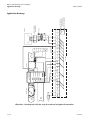
1
Digital Designer’s Guide
Application Note–AN0404H
KMD–7302 Roof Top Unit Controller
This application note describes methods and programming to use
the KMD–7302 as a roof top unit controller with two-stage heating
and cooling and includes optional economizer operation.
Related materials
In addition to the material presented in this installation and operation guide,
review and have available the following reference materials.
◆
◆
◆
◆
Introduction
Installation and operation guides for KMD–7302, MEP–1222 and STE–5100
series or STE–5200 series sensors.
WinControl XL Plus User’s Manual
Hardware Configuration Manager reference guide
System plans with controller addresses
The KMD–7302 Roof Top Unit Controller is a four-input/four-output DDC
Controller specifically designed for operating small air handling units with
two-stage heating and cooling. This device has been pre-programmed with a
KMC supplied control sequence to operate a fan, two stages of heating, and two
stages of cooling to maintain the desired space temperature. An optional
economizer sequence is included for units with modulating outside and return air
dampers.
In addition to the basic control sequence, this device will determine “active” and
“setback” temperature set points as well as primary outside damper positioning
based on occupancy status.
If you do not want to use any of the factory setup and programming options, send
a panel file with your own setup parameters and programming to the controller.
This will remove all of the factory configurations allowing you to program any
desired sequence.
This feature allows the user to custom tailor the control sequence to match
specific applications. The following paragraphs explain the pre-programmed
control sequence in detail and offer suggestions for user-programming to
customize operation of the controllers.
3–141
KMD–7302 Roof Top Unit Controller
Hardware Configuration Manager (HCM)
Hardware
Configuration
Manager (HCM)
KMC Controls
For networked operation, use the HCM software to configure the address, baud,
and last panel setting. Each controller requires a distinct panel address and a
common baud rate to reside on a network. The unit with the highest address must
be designated as LAST PANEL. Before running the HCM software to set these
parameters, flip the network isolation switch located near the terminal strip. See
the Operators Manual for details on HCM and networking controllers.
Table 1 Default Configuration for KMD-7302
Setting up with
WinControl
Panel Number
124
Network Baud Rate
38400
Last Panel
Unchecked
Phone compensation
No
Panel Type
18
This section covers the set-up requirements to activate any of the
pre-programmed options available in this device. At this point, communications
should have been established with the unit.
A “Master” password is available to “sign-on” to each controller. Other security
codes can be entered to control access to the system.
If you do not want to use any of the factory setup and programming options, send
a panel file with your own setup parameters and programming to the controller.
This will remove all of the factory programming allowing you to program any
desired sequence.
The first step after signing on to the controller is to “Load Descriptors One” or
“Load Descriptors All”. Many of the descriptions have been pre-defined for
Inputs, Outputs, and Variables to aid in configuring the options.
To use a program or programs for a specific application, go to the “Control Basic”
programs screen and turn “ON” the appropriate program.
3–142
AN0404H
KMD–7302 Roof Top Unit Controller
Setting up with WinControl
Digital Designer’s Guide
Configuring inputs
All inputs on the KMD Controllers can be selected through software for either
analog or digital ranges. The pre-programmed sequences assume the following
input configuration:
Illustration 1 Input configuration in WinControl XL
Input 1–SPACE TEMPERATURE Default selects a KMC 10k ohm thermistor as
used in all of KMC's STE Series sensors.
Input 2–BASE SET POINT Default range selects Table 2 which has been
pre-defined to correlate slider position of the STE-5200 Series Thermostats into
degrees F. This input is used to determine the active set points for heating and
cooling.
Input 3–MIXED AIR TEMP Default selects standard KMC 10K ohm thermistor in
degrees F. This input is required for operation of the outside air damper with
optional “economizer” programming routine. For STE-1200 series sensors, use
range 2 or 3.
Input 4 - Unused
Configuring outputs
The KMD-7302 Roof Top Unit Controller features five on-board triac relays
(Digital only) and one universal output ( analog or digital, set in software). The
KMC supplied control routines have been written to use the following output
configuration:
Illustration 2 Output configuration in WinControl XL
Output 1– FAN This output uses a 1 amp, zero crossing triac with optical
isolation. It is intended to switch a 24 VAC starter circuit to energize the fan
motor.
AN0404H
3–143
KMD–7302 Roof Top Unit Controller
Setting up with WinControl
KMC Controls
Output 2– HEATING STAGE 1 & 2 Default settings select 0 to 100% range . The
first heating triac turns on above 40% and off below 30%. The second heating triac
turns on when the output is above 80% and turns off below 70%.
Output 3–COOLING STAGE 1 & 2 Default settings select 0 to 100% range . The
first cooling triac turns on above 40% and off below 30%. The second cooling triac
turns on when the output is above 80% and turns off below 70%.
Output 4–OUTSIDE / RET DAMPER his output configuration is set up to
modulate an outdoor damper actuator from 2 to 10 volts ( 0 - 100% open ).
Configuring variables
A total of thirty-two system variables are available to perform various functions
such as set points, limits, and modes. All variables can be changed or modified to
suit the specific application. The following have been pre-defined for use in the
KMC supplied control sequences:
Variable 17–MIXED AIR SET POINT This is the temperature that Controller 3
(CON3) will maintain at the mixed air sensor (IN3) by adjusting the OUTSIDE /
RET DAMPER (OUT4).
Variable 18–COOLING STAGE 1 This variable is ON when the first stage of
cooling is required (the first cooling triac is energized). Manually turning this
variable ON will also force the first stage of cooling on.
Variable 19–COOLING STAGE 2 This variable is ON when the second stage of
cooling is required (the first and second cooling triacs are energized). Manually
turning this variable ON will also force the first and second stages of cooling on.
Variable 20–HEATING STAGE 1 This variable is ON when the first stage of
heating is required (the first heating triac is energized). Manually turning this
variable ON will also force the first stage of heating on.
Variable 21–HEATING STAGE 2 This variable is ON when the second stage of
heating is required (the first and second heating triacs are energized). Manually
turning this variable ON will also force the first and second stages of heating on.
Variable 22–OCCUPANCY STATUS This variable can be toggled to indicate
occupied / unoccupied status by user programming. It is used to start the fan in
occupied times or when cooling or heating are needed in unoccupied mode. The
Default is OCCUPIED. The user must determine the state.
Variable 23–ECONOMIZER OPERATION This variable can be easily toggled to
enable or disable operation of the economizer control sequence. It should be set to
ON when the outside air is suitable for cooling. The Default is DISABLED. The
user must determine the state.
Variable 24– HEAT / COOL MODE Determines if the Roof Top Unit is in the
heating or cooling mode. The default is COOL MODE. If this variable is off, only
heating will take place when required by the space conditions. Cooling will be
inoperable. When this variable is ON the cooling mode is on and only cooling will
take place when required by the space conditions. Heating is disabled in COOL
MODE. The user must determine the state.
3–144
AN0404H
Digital Designer’s Guide
KMD–7302 Roof Top Unit Controller
Setting up with WinControl
Variable 25 and 28–ACTIVE TEMPERATURE SET POINTS These variables are the
temperature set points for cooling and heating that the unit will maintain. In an
unoccupied condition these values become the appropriate “setback”
temperature settings (VAR26 and VAR29). In the occupied mode these values are
calculated based on the “BASE SET POINT” (IN2) and “THERMOSTAT
DEADBAND” (VAR 27). The set points are calculated in Program 1.
Variable 26 and 29–SETBACK TEMPERATURE SET POINTS For cooling and
heating, respectively. These variables are fixed values entered by the user.
Variable 27–THERMOSTAT DEADBAND Our method of determining set points
for cooling and heating insures a neutral range or “deadband”, exists between set
points.
Variable 30–STAGE DELAY This variable establishes the minimum time the first
stage of heating or cooling must run before the second is allowed to start. It also
sets the minimum time between heating and cooling changeover .
Variable 31–FAN DELAY This is the minimum time the fan must run after the
heating or cooling stages have been shut off.
Variable 32–MINIMUM DAMPER POSITION This variable allows easy access to
changing the minimum damper position in an occupied mode as requested by the
control sequence. The Default value is 25% outside air. In the unoccupied mode
the damper output goes to 0%.
Configuring controllers (PID loops)
KMC digital products feature built-in, full function PID (Proportional, Integral,
and Derivative) controllers. In the KMD-7302, Controller 1 is set up as a
direct-acting “cooling” thermostat. It compares SPACE TEMPERATURE (IN1) to
the ACTIVE COOLING SETPT (VAR25) to operate the cooling stages (OUT3).
Controller 2 defines a reverse-acting “heating” thermostat. It compares SPACE
TEMPERATURE (IN1) to the ACTIVE HEATING SETPT (VAR28) to operate the
heating stages (OUT2). Controller 3 compares mixed air temperature (IN3) to the
MIXED AIR SET POINT (VAR17) for operation of the outside air damper in the
economizer cycle. All parameters may be modified as necessary.
AN0404H
3–145
KMD–7302 Roof Top Unit Controller
Setting up with WinControl
KMC Controls
Control Basic programs
Program areas 1 through 4 have specific KMC supplied programming burned
into the controller at the factory. If none of sequence fits the required application,
simply edit the programs or send blank programs to the controller and replace
any of the factory programs. The factory programs can be retrieved if necessary.
The original factory programs can be re-installed again by using the Clear Panel
function in the System Setup Menu.
Caution
This will erase any programming changes that have been made to the
controller. (Clear Panel does not affect changes made with HCM, or panel type)
The following explanations are provided for the KMC supplied programs in the
KMD-7302:
Illustration 3 Control Basic listing
Program 1–SET POINTS The first part of this program serves to define the active
temperature set points for use by the control routine.
In the occupied (VAR22 is ON) mode, the heating set point is calculated by
subtracting half of the
deadband value (VAR27) from the set point indicated on the thermostat dial
(IN2). Similarly, the cooling set point is found by adding half of the deadband to
the thermostat setting.
In the unoccupied mode (VAR22 is OFF) the cooling and heating set points simply
assume the “setback” values defined in Variables 26 and 29 respectively.
Note
“User” programming will be required to change occupancy modes. The KMC
supplied sequence simply defaults to an occupied mode on initial start-up.
This program also contains the basic sequence for the outside air damper. The
damper is opened to minimum position (VAR32) in the occupied mode and is
fully closed in the unoccupied mode. Additional damper control is available
using the optional economizer program (PRG3).
3–146
AN0404H
KMD–7302 Roof Top Unit Controller
Setting up with WinControl
Digital Designer’s Guide
Program 2–FAN / HEAT / COOL The fan is called to operate continuously in the
occupied mode. In the unoccupied mode, if the controllers call for either heating
or cooling to maintain the setback temperatures, the fan will run until the space
temperature has been satisfied. A built-in differential prevents the fan from
cycling on and off due to minor temperature variations.
Note
The triac outputs for heating and cooling are staged. The first stage must be on
when the second stage is on.
In the heating mode (VAR24 is OFF), cooling stages are disabled. Controller 2
controls staging of the heat. If the controller is above 50% and the cooling has
been off for the stage delay (VAR30) period, the first stage of heat will be turned
ON. If the controller gets above 90% (The space continues to be too cold) and the
stage delay (VAR30) for the first stage has timed out, the second stage of heating
is started. The second stage will remain on until the controller falls below 50%.
Both stages will be off once the controller output is below 10%.
In the cooling mode (VAR24 is ON), Heating stages are disabled. Controller 1
controls staging of the cooling. If the controller is above 50% and the heating has
been off for the stage delay (VAR30) period, the first stage of cooling will be
turned ON. If the controller gets above 90% (The space continues to be too warm)
and the stage delay (VAR30) for the first stage has timed out, the second stage of
cooling is started. The second stage will remain on until the controller falls below
50%. Both stages will be off once the controller output is below 10%.
Note
The user must determine Heating and Cooling Mode (VAR24). The default
mode is COOL.
Note
Variables 18, 19, 20, and 21 are the cooling and heating flags. As long as
Program 2 is running, these variables can be used to monitor the staging
sequence. They can also be used to indirectly set the value of the outputs. You
may find it easier to view and work with these variables ( ON and OFF units )
than the output points that have units in percentage.
Program 3–ECONOMIZER If this program is set to “run” and the economizer
cycle is enabled (VAR23 = ON) the outside air damper will be positioned
according to Controller 3, but not less than the minimum damper position
specified in Variable 32. The Controller 3 compares mixed air temperature (IN3) to
the mixed air set point as defined in Variable 17. The damper is controlled as a
direct acting cooling device. If the mixed air temperature falls below the set point,
the damper will be modulated closed to bring the temperature back to set point.
Program 4 and 5 - Available for user programming Program areas 4 and 5 are
typically used to customize the control sequences for each particular application.
The following sections discuss some of the most common options used with this
model. The user will need to set values for OCCUPANCY MODE, ECONOMIZER
MODE, and HEAT / COOL MODE in a program. It may also be necessary to
AN0404H
3–147
KMD–7302 Roof Top Unit Controller
Custom tables
KMC Controls
establish fan status here before running the cooling or heating. For complete
details on writing your own custom logic in Control Basic Language, refer to the
WinControl manual.
Custom tables
Custom tables allow the user to create unique “ranges” to be used by inputs or
other special applications. The most often used application of these custom tables
is to establish a correlation between a potentiometer setting (a voltage) and a
temperature value (such as the dial setting on a thermostat). The KMD-7000 Series
Controllers allow user-access to all 3 tables. These tables have been defined for the
following applications in the KMD-7302:
Table1 Available for user programming.
Table 2: Correlates slider position of STE-5200 Series Thermostat into degrees F.
Table 3 Correlates the dial setting of STE-5000 Series Thermostat Sensor to
degrees F.
These tables use nominal values for correlation. Due to component tolerances and
the resistance of field wiring, these values may need correction on an individual
basis. If the value read is too low, enter a positive calibration in the input column
labeled “cal”. If the value read is high, a negative calibration can be entered. . If
necessary, reconfigure Table 2 and/or Table 3. The complete Table 2 and Table 3
from the factory are shown. If the tables have been reconfigured and the user
wants the factory configuration for Table 2 and Table 3 it will be necessary to use
Clear Panel or re-enter the values.
Note
Using Clear Panel will erase any programming changes that have been made
to the controller. (Clear Panel does not affect changes made with HCM, or
panel type.)
3–148
AN0404H
Digital Designer’s Guide
Occupancy status
KMD–7302 Roof Top Unit Controller
Occupancy status
For simplicity, a system variable (VAR22) has already been defined as an
“occupied status” indication. The KMC supplied routines do not define what
constitutes an “occupied” status. However, the KMC supplied routines do
reference the status of this variable when determining room set points or for
outside air damper operations. Typically, the occupancy status is determined by
reference to a time schedule by writing a line of code in Program 5 such as:
10 IF WS1 THEN START VAR22 ELSE STOP VAR22
Where WS1 is weekly schedule 1 as defined in the KMD-7302 panel. Scheduled
times are assigned with up to four ON and four OFF times per day, for each day
of the week. See the WinControl manual.
Economizer
If you choose to use the KMC supplied economizer routine it will be necessary to
determine when an economizer cycle can be allowed. An efficient method to do
this is to compare outside and inside enthalpy. Operation of the economizer is
then based on where the air handler can get the least expensive cooling. The
lower the enthalpy is, the lower the heat content of the air. If the enthalpy is lower
outside then the economizer is enabled. If the enthalpy is lower inside, the
economizer is disabled. Here is an example of programming to make this
comparison:
20 IF OUT-ENTH < IN-ENTH -1 THEN ENABLE VAR23
30 IF OUT-ENTH > IN-ENTH THEN DISABLE VAR23
In this example “OUT-ENTH” is the calculated outdoor enthalpy and
“IN-ENTH” is the calculated indoor enthalpy. To make these calculations it is
necessary to have outside temperature and humidity sensors as well as space or
return air humidity and temperature sensors. A more simplistic approach to
enabling the economizer is to look at outside air temperature. The following
example looks at outside air and the cooling demand based on the controller
output to the cooling valve:
20 IF CON1 > 5 AND OAT < 65 THEN ENABLE VAR23
30 IF CON1 < 1 OR OAT > 67 THEN DISABLE VAR23
This example requires a cooling demand (CON1) of greater than 5% and an
outside air temperature (OAT) of less than 65 degrees before economizer
operation is allowed. Once enabled, the economizer cycle will be disabled if either
the demand for cooling falls off or the outside air temperature rises above 67
degrees.
Heating/cooling
mode
The KMC supplied program 2 uses Variable 24 to lockout cooling when heating is
required and to lock-out heating when cooling is required. The mode can be
selected based on factors such as outside air temperature and space temperature.
40 IF NOT ECONOMIZ AND OAT > 58 THEN START H/C-MODE
50 IF ECONOMIZ OR OAT < 55 THEN STOP H/C-MODE
AN0404H
3–149
KMD–7302 Roof Top Unit Controller
Fan proof
KMC Controls
This example uses the economizer variable to determine when the outside air is
no longer suitable for cooling as a means of enabling mechanical cooling.
ECONOMIZE (VAR23) is off when the damper is allowed to modulate past
minimum position (VAR32).
Fan proof
The fourth input (IN4) is available for some type of fan proof device. This may be
an airflow switch, current transducer, or an auxiliary starter contact to show the
fan has started. You can prohibit the heating and cooling from operating without
the fan by adding a line of code in Program 5 such as:
60 IF NOT FAN$STAT THEN COOL$STG = 0 , HEAT$STG = 0
Where FAN$STAT is proof the fan is running (IN4). Setting COOL$STG and
HEAT$STG to 0 will keep all stages from operating until the fan has started.
Temperature
setpoints
This model has been pre-programmed assuming a set point potentiometer is
connected to Input 2. In some cases, it may be desirable to provide a “fixed” set
point in the software to free up the input for another purpose (or have a
standardized set point for the whole building). The KMC supplied sequence
determines the heating and cooling set points in an occupied mode as half the
deadband below and above IN2 set point respectively. To change this to a fixed set
point, simply write a line of code in Program 5 such as:
70 IF OCCUPIED THEN HEAT$SPT = 72 , COOL$SPT = 74
Different numbers or reference variables can substitute the numbers 72 and 74.
Also note the KMC supplied sequence defines the unoccupied heating and
cooling set points by referencing “setback” variables. These too can be modified if
necessary, or the cooling and heating set points can be set directly as shown
below:
80 IF NOT OCCUPIED THEN HEAT$SPT = 66 , COOL$SPT = 76
Using the NetSensor
A NetSensor can be used to bring values into the controller without using any
physical input. To add a NetSensor and use the factory programming in the
KMD-7302, simply change the PID controllers 1 and 2 in-label from IN1 to the
variable mapped to the NetSensor's onboard temperature sensor. Change
SETPT$TP in line 60 and line 70 of program1 to a variable mapped to button 2 on
the NetSensor.
Other options
One of the biggest features of any KMC digital DDC Controller is the inherent
programming ease and flexibility available in each and every unit. If the KMC
supplied sequences do not satisfy the application at hand they may be turned off
or edited and the entire control strategy can be manipulated. The KMDC digital
Technical Operator's Manual provides help and examples for programming
Control Basic.
3–150
AN0404H
KMD–7302 Roof Top Unit Controller
WinControl settings
Digital Designer’s Guide
WinControl settings
The following tables display the WinControl XL Plus settings for this applications
note.
Table 2 Inputs
Description
Manual
Value
Units
1
SPACE TEMPERATURE
Auto
236.483
Deg.F KMC10K Type II 64
SPACE$TP
2
BASE SET POINT
Auto
55
Table 2
SETPT$TP
3
MIXED AIR TEMP
Auto
184.042
Deg.F KMC10K Type II 64
Auto
0
Unused
4
Average
64
Label
MIXED$TP
64
Table 3 Output
Description
Manual
Value
Units
0%
1
FAN
Auto
On
Off/On
2
HEATING STAGE 1 & 2
Auto
0
0-100% 0.0
3
COOLING STAGE 1 & 2
Auto
0
4
OUTSIDE / RET DAMPER Auto
25
100%
Security
Delay
Label
0
FAN
10
0
HEAT$STG
0-100% 0.0
10
0
COOL$STG
0-100% 2.0
10
0
OUT$DMPR
Table 4 Variables
AN0404H
Description
Manual
Value
Units
Label
1-16
Available for user programs
Auto
0
17
MIXED AIR SET POINT
Auto
55
Degrees Fahrenheit
MIXD$SPT
18
COOLING STAGE 1
Auto
Off
Off/On
COOLSTG1
19
COOLING STAGE 2
Auto
Off
Off/On
COOLSTG2
20
HEATING STAGE 1
Auto
Off
Off/On
HEATSTG1
21
HEATING STAGE 2
Auto
Off
Off/On
HEATSTG2
22
OCCUPANCY STATUS
Auto
Occupied Unocc/Occ
OCCUPIED
23
ECONOMIZER OPERATION
Auto
Disabled
Dis/Enabled
ECONOMIZ
24
HEAT / COOL MODE
Auto
Cool
Cool/Heat
H/C-MODE
25
ACTIVE COOLING SETPT
Auto
57
Degrees Fahrenheit
COOL$SPT
26
SETBACK COOL SETPT
Auto
80
Degrees Fahrenheit
C$SETBK
27
T'STAT DEADBAND
Auto
4
Degrees Fahrenheit
DEADBAND
28
ACTIVE HEATING SETPT
Auto
53
Degrees Fahrenheit
HEAT$SPT
29
SETBACK HEAT SETPT
Auto
62
Degrees Fahrenheit
H$SETBK
30
STAGE DELAY
Auto
0:03:00
Time
STAGEDEL
31
FAN DELAY
Auto
0:03:00
Time
FANDELAY
32
MIN. DAMPER POSITION
Auto
25
Percent %
MIN$DMPR
3–151
KMD–7302 Roof Top Unit Controller
WinControl settings
KMC Controls
Table 5 Tables
#
Table 1
Unused
Table 2
Unused
Table 3
Unused
1
0
0
0
86
0
54
2
0
0
0.71
85
0.05
54
3
0
0
1.07
80
0.538
58
4
0
0
1.38
75
0.939
62
5
0
0
1.67
70
1.27
66
6
0
0
1.91
65
1.42
68
7
0
0
2.1
60
1.56
70
8
0
0
2.23
56
1.68
72
9
0
0
3
55
1.8
74
10
0
0
5
55
1.91
76
11
0
0
0
0
2.01
78
12
0
0
0
0
2.2
82
13
0
0
0
0
2.36
86
14
0
0
0
0
2.5
90
15
0
0
0
0
3
90
Table 6 Control Basic listing
PRG
Description
On
Manual
#1
SET POINTS
YES
Auto
#2
FAN / HEAT / COOL
YES
Auto
#3
ECONOMIZER
NO
Auto
NO
Auto
NO
Auto
#4
#5
USER PROGRAMMING
Label
Program 1–SET POINTS
30
50
60
70
REM DETERMINING ACTIVE SETPOINTS BASED ON OCCUPANCY MODE
IF NOT VAR22 THEN VAR25 = VAR26 , VAR28 = VAR29
IF VAR22 THEN VAR25 = IN2 + VAR27 / 2
IF VAR22 THEN VAR28 = IN2 - VAR27 / 2
100 REM *** Outside Damper Operation ***
110 IF VAR22 THEN OUT4 = VAR32 ELSE OUT4 = 0
300 END
3–152
AN0404H
KMD–7302 Roof Top Unit Controller
WinControl settings
Digital Designer’s Guide
Program 2–FAN / HEAT / COOL
30 REM *** FAN Control ***
40 IF OCCUPANCY~STATUS OR COOLING~STAGE~1~&~2 >= 50 OR
HEATING~STAGE~1~&~2 >= 50 THEN START FAN
50 IF NOT OCCUPANCY~STATUS AND TIME-OFF( HEATING~STAGE~1 ) >
FAN~DELAY AND TIME-OFF( COOLING~STAGE~1 ) > FAN~DELAY THEN STOP
FAN
60 REM *** Cooling / Heating ***
70 IF HEAT~/~COOL~MODE THEN 160 : REM Heat mode skips over
cooling sequence!
80 REM *** COOLING MODE ***
90 STOP HEATING~STAGE~1 : STOP HEATING~STAGE~2 : REM TURN OFF
HEATING
100 IF CON2 < 10 THEN STOP COOLING~STAGE~1 , STOP
COOLING~STAGE~2
110 IF CON2 > 50 AND TIME-OFF( HEATING~STAGE~1 ) > STAGE~DELAY
THEN START COOLING~STAGE~1
120 IF CON2 > 90 AND TIME-ON( COOLING~STAGE~1 ) > STAGE~DELAY
THEN START COOLING~STAGE~2
130 IF CON2 < 50 THEN STOP COOLING~STAGE~2
140 IF NOT COOLING~STAGE~1 THEN STOP COOLING~STAGE~2
150 GOTO 230
160 REM *** HEATING MODE ***
170 STOP COOLING~STAGE~1 : STOP COOLING~STAGE~2 : REM TURN OFF
COOLING
180 IF CON1 < 10 THEN STOP HEATING~STAGE~1 , STOP
HEATING~STAGE~2
190 IF CON1 > 50 AND TIME-OFF( COOLING~STAGE~1 ) > STAGE~DELAY
THEN START HEATING~STAGE~1
200 IF CON1 > 90 AND TIME-ON( HEATING~STAGE~1 ) > STAGE~DELAY
THEN START HEATING~STAGE~2
210 IF CON1 < 50 THEN STOP HEATING~STAGE~2
220 IF NOT HEATING~STAGE~1 THEN STOP HEATING~STAGE~2
230 IF NOT COOLING~STAGE~1 AND NOT COOLING~STAGE~2 THEN
COOLING~STAGE~1~&~2 = 0
240 IF COOLING~STAGE~1 THEN COOLING~STAGE~1~&~2 = 50
250 IF COOLING~STAGE~2 THEN COOLING~STAGE~1~&~2 = 100
260 IF NOT HEATING~STAGE~1 AND NOT HEATING~STAGE~2 THEN
HEATING~STAGE~1~&~2 = 0
270 IF HEATING~STAGE~1 THEN HEATING~STAGE~1~&~2 = 50
280 IF HEATING~STAGE~2 THEN HEATING~STAGE~1~&~2 = 100
290 END
Program 3–ECONOMIZER
30 REM *** ECONOMIZER CYCLE ***
40 IF NOT ECONOMIZER~OPERATION THEN END
50 IF NOT OCCUPANCY~STATUS THEN END
60 OUTSIDE~/~RET~DAMPER = CON3
70 IF OUTSIDE~/~RET~DAMPER < MIN.~DAMPER~POSITION THEN
OUTSIDE~/~RET~DAMPER = MIN.~DAMPER~POSITION
80 END
AN0404H
3–153
FROM PREV. DEVICE "A"
FROM PREV. DEVICE "B"
TO NEXT DEVICE "A"
TO NEXT DEVICE "B"
B
STE-5112-10
A
STE-5200 SERIES
THERMOSTAT OPTION
STE-52XX
A
B
IN1
C
GND
GND
GND T
IN2
IN-1
IN-2
IN-3
GND
OUT-4
IN-4
SP
AC
E$
TP
SE
TP
T$
TP
MI
XE
D$
TP
SP
GND
24VAC
GND
KMD-7302
T1
STE-1214
LINK N.O.
T2-B
HE
AT
$S
TG
TRIAC T2-A
RET
MEP-1222
KMC
LINK N.C.
OUTSIDE
AIR
0-10VDC
FA
N
T3-B
HEATSTG 2
HEATSTG 1
C2
C1
H2
H1
GND
24VAC
D
H
R
ROOF TOP UNIT
X
GND
OU
T$
DM
PR
TRIAC OUT-4
RET
COOLSTG 1
24VAC
COOLSTG 2
FAN
TRIAC T3-A
RET
CO
OL
$S
TG
RTU CONTROL PANEL
24VAC CIRCUITS
120VAC
RET.
AIR
DIS.
AIR
AN0404H
3–154
KMC Controls
KMD–7302 Roof Top Unit Controller
Application drawings
Application drawings
Illustration 4 Rooftop unit with two–stage heat and cool and optional economizer.