1
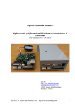
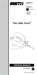
myCNC control & software.
Manual (rev 0.02 Preliminary)
myCNC
http://www.bevelcutting.com
email: [email protected]
195257, Russia, Saint-Petersburg
Severny st. 73-1-91
myCNC, CNC control and software. © 2010. http://www.bevelcutting.com
1
Using This Manual
This user manual provides information for proper installation of the myCNC controllers and
operation of machining centers based on myCNC control software.
WARNING: Machinery in motion can be dangerous! It is the responsibility of the user to design
effective error handling and safety protection as part of the machinery. myCNC shall not be
liable or responsible for any incidental or consequential damages
Table of content
myCNC control & software. .......................................................................................................1
1
Introduction ........................................................................................................................5
2
myCNC-XXX Functional units ...........................................................................................5
2.1. CPU unit section .........................................................................................................6
2.2. Motor Interface ...........................................................................................................6
2.3. Communication...........................................................................................................6
2.4. myCNC peripherals. ....................................................................................................6
2.5. System Elements .........................................................................................................7
3
myCNC-XXX hardware......................................................................................................7
3.1. myCNC-UP3 controller board. ....................................................................................7
3.1.1
myCNC-UP3 board connections ..........................................................................9
Power supply...................................................................................................................9
Motor Interface. ..............................................................................................................9
Motor driver connection samples................................................................................... 10
Opto-isolated inputs. ..................................................................................................... 11
PWM outputs, DAC output. .......................................................................................... 13
ADC inputs. .................................................................................................................. 14
3.1.2
myCNC-UP3 connection example. .................................................................... 15
Oxy-fuel cutting machine .............................................................................................. 15
3.2. Programmable Logic controller (PLC)....................................................................... 17
3.2.1
PLC programming language. ............................................................................. 17
Operators ...................................................................................................................... 17
Control structures.......................................................................................................... 17
Functions. ..................................................................................................................... 18
3.2.2
Compilation PLC program................................................................................. 19
3.2.3
Running PLC program....................................................................................... 19
Immediate running PLC program. ................................................................................. 19
Running PLC programs synchronized with motion........................................................ 22
Table 1. PLC variables for access to ADC, DAC and PWM
Table 2. X18 pin description, power supply
Table 3. Connectors XT1-XT8 pin connection
Table 4. Settings for digital inputs power supply.
Table 5. ADC inputs electrical characteristics.
Table 6. ADC connectors pin description.
Table 7. PLC language operators.
Table 8. PLC language control structures.
Table 9. PLC language predefined functions.
Table 10. PLC function reserved variables.
Table 11. PLC program names.
7
9
9
11
14
14
17
18
18
18
22
Figure 1. myCNC-UP3 board (revision 2)...................................................................................8
Figure 2. myCNC-UP3 board outline ..........................................................................................8
Figure 3 STEP/DIR interface schematic design......................................................................... 10
Figure 4. Panasonic minas series servo driver (differential high speed input) connection to the
myCNC-XXX........................................................................................................................... 10
Figure 5. .Panasonic minas series servo driver (opto-isolated input) connection to the myCNCXXX......................................................................................................................................... 11
myCNC, CNC control and software. © 2010. http://www.bevelcutting.com
3
Figure 6. Motor interface connectors (XT1…XT8). myCNC-UP3 controller. ........................... 11
Figure 7. myCNC-UP3 Opto-isolated inputs schematic design.................................................. 12
Figure 8. myCNC-UP3 Opto-isolated. PCB layout................................................................... 12
Figure 9. PWM outputs, DAC output schematic design............................................................. 13
Figure 10. PWM outputs, DAC output board layout.................................................................. 13
Figure 11. ADC inputs schematics. ........................................................................................... 14
Figure 12. ADC inputs connectors layout.................................................................................. 15
Figure 13. myCNC-UP3 inputs connection example. ................................................................ 16
Figure 14. myCNC-UP3 relays, PWM outputs connection example. ......................................... 16
Figure 15. myCNC siftware. Addition on-screen buttons. ........................................................ 21
myCNC, CNC control and software. © 2010. http://www.bevelcutting.com
4
1 Introduction
The myCNC-U and myCNC-E series of motion controllers were developed specifically multiaxes applications. This manual covers one USB based and one Ethernet/USB based controllers in
myCNC series.
The myCNC-UP3 is 6 axes motion controller that communicates with HMI software via the
USB. The myCNC-ET1 is 6 axes motion controller that communicates with HMI myCNC
control software via Ethernet or USB (can be configured via USB with configuration software).
Performance capability of these controllers includes:
§ STEP/DIR output command with maximum pulse frequency is 1MHz for myCNC-UP3
controller and 3MHz for myCNC-ET1;
§ Motion controller processing time is 256us/82us for myCNC-UP3/ET1 controllers;
§ Virtual machine processing time for integrated PLC controller and peripheral units (relay
outputs, opto-isolated inputs, PWS, DAC outputs, ADC inputs) is 1ms;
§ 1…8 Mbytes flash memory for PLC program, motion program and parameters storage
for maximum flexibility.
myCNC controllers can be interfaced to a variety of drives which accept STEP/DIR or
STEP+|STEP- signals. Modes of motion include jogging, point-to-point positioning and
contouring. Electronic gearing is available via myCNC control software. Several motion
parameters can be specified including acceleration and deceleration rates.
For synchronization with outside events, the myCNC-XXX provides uncommitted I/O.
The myCNC-UP3 provides 8 opto-isolated inputs, 6 relay outputs, 3PWM outputs, 4 TTL
outputs, 1 DAC (0…10V) and 2 ADC inputs.
The myCNC-ET1 provides 16 opto-isolated inputs, 6 relay outputs, 3PWM outputs, 7 open
collector key outputs, 1 DAC (0…10V) and 5 ADC inputs.
Committed digital inputs can be configured as abort, jog, start and home events or can be
flexibly used while machining process via PLC controller.
For communication between controller and HMI software specially designed binary half-duplex
master-slave protocol is used.
To prevent system damage during machine operation, the myCNC-XXX provides many error
handling features. These include software and hardware limits, automatic shut-off on excessive
error, user-definable abort input.
With firmware upgrade myCNC-ET1 will be able to work in stand-alone applications and
provide non-volatile storage for programs.
2 myCNC-XXX Functional units
The myCNC-XXX circuitry can be divided into the following functional elements:
myCNC, CNC control and software. © 2010. http://www.bevelcutting.com
5
CPU unit – ARM based microcomputer (512k Flash, 64k RAM) 70MHz for myCNC-UP3 and
100MHz for myCNC-ET1 board;
§ Motor interface based on Altera FPGA programmable logic;
§ 2/5 channel (myCNC-UP3/ET1) General purpose ADC 0...5V, programmable via PLC;
§ 1 general purpose DAC, programmable via PLC;
§ 3 channel Power PWM (24V 2A), programmable via PLC;
§ 6 open collector (24V, 0.25A) outputs (myCNC-ET1 board only), programmable via
PLC;
§ 8/16 opto-isolated digital inputs (myCNC-UP3/ET1), programmable via PLC;
§ 7 relay outputs, programmable via PLC;
§ USB slave with USB-to-serial converter for communication with HMI;
§ USB master controller for USB flash drive connection (myCNC-ET1 board only)
§ Ethernet controller for HMI connection – myCNC-ET1 board only;
§ Graphic LCD display (122x32 pixels) – myCNC-ET1 only;
§ 9 key membrane keyboard – myCNC-ET1 only;
2.1. CPU unit section
The main processing unit of the myCNC-XXX is a 32-bit NXP ARM7tdmi (myCNC-UP3) or
Cortex-M3 (myCNC-ET1) series microcontrollers with 512 kbytes internal Flash memory, 1-8
Mbytes external flash memory and 64 kbytes RAM memory. The RAM provides memory for
variable storage and application programs. The external flash memory provides non-volatile
storage of variables, motion and PLC programs, and arrays. Internal flash memory contains the
myCNC-XXX firmware.
2.2. Motor Interface
Altera FPGA programmable logic installed on myCNC-XXX controllers provide high speed,
precise and smooth STEP/DIR motor interface.
2.3. Communication
For communication myCNC-XXX controllers with HMI control software USB, Ethernet and
RS485 (optional) interface can be used
The communication interface with the myCNC-UP3 controller consists of one USB port (with
integrated USB-to-serial converter at speed 500 kbaud) and one RS485 interface with speed
115.2 kbaud, that can be used as slave interface with HMI Host software or as master interface
for myCNC-THC-RU01 connection (torch height control board for CNC plasma cutting tables)
In addition to interfaces listed above, myCNC-ET1 controller board has 10base-T Ethernet port,
which is used for HMI connection.
2.4. myCNC peripherals.
myCNC controllers have wide range of peripherals (ADC, DAC, PWM, Inputs, outputs).
Peripherals control is available via integrated PLC. There are available operations that
synchronized with motion and asynchronous operations which run immediately.
All peripherals is available via PLC reserved variables.
myCNC, CNC control and software. © 2010. http://www.bevelcutting.com
6
In a table below there are PLC variable names and peripherals that assigned to it.
PWM, ADC and DAC are 12-bit values. Complete range for these variables is 0…4095 (in hex
0…0x7ff)
Table 1. PLC variables for access to ADC, DAC and PWM
PLC variable name
pwm01
pwm02
pwm03
pwm04
adc1
adc2
Peripherals
PWM1
PWM2
PWM3
Reserved
ADC1
ADC2
Digital inputs available via PLC function:
getport(int port_number)
//read digital input nr. (port_number+1); return value is 0 if
input pin open, 1 if closed;
Digital outputs available via PLC functions:
portset(int port_number); //turn on relay nr. (port_number+1)
portclr(int port_number); //turn off relay nr. (port_number+1)
Samples:
1. Turn on relay nr.3 and turn off relay nr.1
portset(2); // turn on relay output nr.3
portclr(0); // turn off relay output nr.1
2. if input pin nr.5 is open turn off PWM channel nr. 1, otherwise turn on it on a half of
maximum;
if (portget(4)==0)
pwm=0;
else
pwm01=2048;
3. PWM channel nr. 2 repeats value on ADC channel nr.1
pwm02=adc01;
2.5. System Elements
the myCNC-XXX is part of a motion control system which includes servo (with encoders) or
stepper motors, motor drivers, power supply;
3 myCNC-XXX hardware.
3.1. myCNC-UP3 controller board.
myCNC, CNC control and software. © 2010. http://www.bevelcutting.com
7
Figure 1. myCNC-UP3 board (revision 2).
Figure 2. myCNC-UP3 board outline
myCNC, CNC control and software. © 2010. http://www.bevelcutting.com
8
3.1.1 myCNC-UP3 board connections
Power supply.
Connector X18 is used for power supply 24V DC connection.
Table 2. X18 pin description, power supply
Pin nr.
1
2
Description
24V DC
GND / COMMON
Motor Interface.
myCNC-UP3 board contains 8 connectors for each motor axes (X, Y, Z, A, B, C, #7, #8) –
XT1 for axis X,
XT2 for axis Y,
XT3 for axis Z,
XT4 for axis A,
XT5 for axis B,
XT6 for axis C,
XT7..XT8 for axes #7 & #8
For STEP/DIR motor interface is used high speed differential line driver compatible with
RS422/RS485.
Table 3. Connectors XT1-XT8 pin connection
Pin Nr.
1
2
3
4
5
6
Name in STEP/DIR mode
+5V output supply
STEP
~STEP
DIR
~DIR
GND/COMMON
Name in STEP+ STEP- mode
+5V output supply
STEP+
~STEP+
STEP–
~STEP–
GND/COMMON
myCNC, CNC control and software. © 2010. http://www.bevelcutting.com
9
Figure 3 STEP/DIR interface schematic design
Motor driver connection samples.
This transmission method is recommended for better noise immunity. Maximum pulse frequency
up to 2 Mpps.
Figure 4. Panasonic minas series servo driver (differential high speed input) connection to the myCNC-XXX
For opto-isolated inputs isrecomended maximum pulse frequency low than 500kpps
myCNC, CNC control and software. © 2010. http://www.bevelcutting.com
10
Figure 5. .Panasonic minas series servo driver (opto-isolated input) connection to the myCNC-XXX
Figure 6. Motor interface connectors (XT1…XT8). myCNC-UP3 controller.
Opto-isolated inputs.
The myCNC-UP3 contains 8 opto-isolated inputs for connection any type sensors, keys,
switchers. Schematic design is shown on the figure below.
For LED power supply can be used internal +24V DC power supply or external power supply
12…24V DC (For complete digital input optical isolation).
Configuration for internal/external power supply is shown on a table below.
Table 4. Settings for digital inputs power supply.
External power supply 12…24V DC for digital
inputs
Internal power supply 24V DC for digital
inputs
J2 is open; J3 – (2-3) is closed
J2 is closed; J3 – (1-2) is closed
myCNC, CNC control and software. © 2010. http://www.bevelcutting.com
11
Figure 7. myCNC-UP3 Opto-isolated inputs schematic design.
Figure 8. myCNC-UP3 Opto-isolated. PCB layout.
myCNC, CNC control and software. © 2010. http://www.bevelcutting.com
12
PWM outputs, DAC output.
The myCNC-UP3 board contains 3 PWM output and DAC output.
Schematic of DAC and PWM peripherals is shown on a figure below.
PWM outputs are “open drain”. Power supply for output transistor keys can be internal supply
24V DC or external power supply (up to DC 80V).
External power supply for PWM outputs
Internal power supply 24V DC for PWM
outputs
J6 is open, Power supply is connected to X1.
GND/COMMON to pin nr.10; VCC to pin nr.9
J6 is closed.
Figure 9. PWM outputs, DAC output schematic design.
Figure 10. PWM outputs, DAC output board layout.
myCNC, CNC control and software. © 2010. http://www.bevelcutting.com
13
ADC inputs.
The myCNC-UP3 contains 2 ADC inputs. There are two connectors X2 & X4 for connection
analog sensors to myCNC-UP3 controller. The connectors have +5V power supply output for
convenience to use active analog sensors like flow/pressure sensors, capacitory or inductive
sensors that need external power supply. Power supply is protected with 120mA fuse.
ADC inputs schematic design is provided on a figure below.
Figure 11. ADC inputs schematics.
Table 5. ADC inputs electrical characteristics.
Parameter name
Input voltage range for ADC inputs
Pre-defined PLC variables for access to ADC
values
Sample rate (for each channel)
Value
0…5V
adc01 for input nr.1
adc02 for input nr.2
1ms
Table 6. ADC connectors pin description.
Pin nr.
1
2
3
Description
External power supply 5V DC (protected by fuse 120mA)
ADC input (0…5V)
GND/COMMON
myCNC, CNC control and software. © 2010. http://www.bevelcutting.com
14
Figure 12. ADC inputs connectors layout.
3.1.2 myCNC-UP3 connection example.
All myCNC-XXX peripherals available through PLC controller so all signals can be flexibly
reassigned. Ther is no fixed configuration for myCNC-XXX controller.
For any profile (plasma, oxy-fuel cutting table, mill, lathe, engraving and so on) can be created
or modified myCNC configuration. Let’s see example
Oxy-fuel cutting machine
Simple oxy-fuel cutting machine has:
§ Two axes – X & Y;
§ Two external key – start & stop;
§ Four limit switches - +X, -X, +Y, -Y
§ Three pneumatic valves for gas control (cutting oxygen, preheat oxygen, fuel gas); one of
them is proportional (cutting oxygen)
For this example motor drivers are connected to XT1, XT2 connectors.
Connection of external keys is shown on figure below. In this configuration is easy to use
internal power supply:
Internal power supply 24V DC for digital
J2 is closed; J3 – (1-2) is closed
inputs
myCNC, CNC control and software. © 2010. http://www.bevelcutting.com
15
Figure 13. myCNC-UP3 inputs connection example.
Pneumatic valves connection is shown on a figure below.
Figure 14. myCNC-UP3 relays, PWM outputs connection example.
myCNC, CNC control and software. © 2010. http://www.bevelcutting.com
16
For valves power supply is used internal 24V DC source, so J6 should be closed.
Internal power supply 24V DC for PWM
outputs
J6 is closed.
3.2. Programmable Logic controller (PLC)
myCNC-XXX boards have integrated Programmable Logic Controller (PLC) to control all onboard peripherals. PLC is virtual machine which is run every 1ms.
3.2.1 PLC programming language.
PLC can be programmed with simple “C”-like language.
The language syntax.
Operators
Table 7. PLC language operators.
Operation
Assignment
Subtraction
Multiplication
Division
Increment (suffix)
Decrement (suffix)
Syntax
a=b
a–b
a*b
a/b
a ++
a––
Equal to
Not equal to
Greater than
Less than
Greater than or equal
Less than or equal
a==b
a!=b
a>b
a<b
a >= b
a <= b
Bitwise left shift
Bitwise right shift
a << b
a >> b
Bitwise AND
Bitwise OR
Bitwise XOR
a&b
a|b
a^b
Comments
Control structures
Control structures can operate with§ Statement;
myCNC, CNC control and software. © 2010. http://www.bevelcutting.com
17
§ Compound-statement or block.
Compound-statement –s group of statements are separated by semicolons (;) and enclosed
together in braces: { }
{statement1; statement2; statement3;}
Table 8. PLC language control structures.
Control structure
Conditional structure
Iteration structure
(loops)
Syntax
if (condition) statement
if (condition) statement1
else statement2
do statement while
(condition);
Example
if (a <0) b=1;
if (a <0) b=1;
else b=2;
do
{
pwm01=timer*2;
timer++;
}while (timer<100);
ATTENCION! It’s important.
For do{}while structure each iteration runs every 1ms.
All timing generation in PLC programs is based on this rule.
Functions.
There is no feature to define your own functions/subroutines in PLC language.
Some pre-defined functions are available for control PLC binary peripherals.
Table 9. PLC language predefined functions.
Function
portset(int n)
portclr(int n)
portget(int n)
Description
Set to logical “1” binary output port number “n”
Clear to “0” binary output port number “n”
Return current value of input binary port number “n”
Table 10. PLC function reserved variables.
Name
timer
message
proc
eparam
dac01, dac02
Description
1ms counter which is available from myCNC control software.
With this counter can be made ProgressBar or some other on-screen
info elements.
Message from PLC to myCNC controller. It’s used for
start/continue/break motion program from PLC.
Variable is available from myCNC software and can be used onscreen info elements (for example during oxyfuel cutting show
ignition/preheat/piercing/cutting on-screen info)
PLC program is executed with param value. This value is send into
PLC variable eparam and can be used in PLC program.
These variables represent DAC outputs. By writing to this variable
we change value on DAC output pins.
myCNC, CNC control and software. © 2010. http://www.bevelcutting.com
18
adc01…adc04
pwm01…pwm04
These variables represent ADC inputs. By reading these variable
we read value of AD converter that connected to input ADC pins.
These variables represent PWM outputs. By writing to these
variables we change pulse width value on PWM output pins.
3.2.2 Compilation PLC program.
myCNC-XXX controller operate with PLC program by 8-letters name. A file with PLC source
function should have extension “plc”.
Special utility “plc.make” for Linux or “plc.make.bat” for Windows compiles source file, places
compiled bytecode file into “bytecode” folder and then create “eeprom.rom” disk image in
“romfs” filesystem in a folder “eeprom”. You can check this file after running plc.make utility.
This disk image file is uploaded into myCNC controller during start of myCNC control software.
3.2.3 Running PLC program.
There are two scenario about running PLC programs (functions)
1. myCNC software can run immediately PLC program
2. PLC program call code can be inserted into motion program so running PLC program
will be synchronized with motion.
Immediate running PLC program.
Let’s see step-by-step example how-to create on-screen button, write PLC procedure, compile it
and assign this procedure to the button.
For example:
we need to turn on relay nr.1 for 0.5 sec, then turn on relay nr.2 and so on. Procedure is finished
when all relays (7 of them) are turned on. If input port nr.1 is closed, procedure breaks and all
relays is turned off.
Source for this procedure is listed below
i=0;
timer=0;
portset(i);
do
{
timer++;
if (getport(1)!=0)
{
portclr(0);
portclr(1);
//if we need to switched off relays
//immediately, we can’t use loop
myCNC, CNC control and software. © 2010. http://www.bevelcutting.com
19
portclr(2);
portclr(3);
portclr(4);
portclr(5);
portclr(6);
exit(99);
}
if (timer==500)
{
timer=0;
i++;
portset(i)
};
} while (i<7)
exit(0);
//normal exit from procedure
Create the source and save with name “M101.plc” into “pdata/plc/src” folder.
Run plc.make.bat (for MS Windows) or plc.make.sh (for Linux). Check if in
pdata/plc/bytecode folder compiled file “M101” exists.
To create on-screen button we need to study configuration file “cnc-config.xml” in “pdata”
folder. Graphic items like buttons, info, labels, progress bars etc can be added into widgets which
value is “mytems”.
Find “screen” section:
<screen>
<work-layouts>
<current>layout-table-1x1-v1</current>
<layout name="layout-table-1x1-v1" orientation="horizontal">
<layout stretch="0" orientation="vertical">
<widget widget-name="widget-a" stretch="0">myitems</widget>
<widget widget-name="w-left-bottom" stretch="0"
orientation="horizontal" >myitems</widget>
</layout>
<layout stretch="1" orientation="vertical">
<widget widget-name="work-toolbar" stretch="0">myitems</widget>
<widget widget-name="nc-view" stretch="3">ncview</widget>
<widget widget-name="nc-progress" stretch="1">ncprogress</widget>
</layout>
…………..
For example we like to add the button into widget with name “widget-a”.
Then find in this file graphic items which is placed in this widget. So find “widget-a” in the file.
<gitem widget-name="widget-a" type="button-group" height="90" action="playerplay;player-stop" skin="01" orientation="horizontal">
</gitem>
myCNC, CNC control and software. © 2010. http://www.bevelcutting.com
20
<gitem widget-name="widget-a" type="button-group" height="50" action="player-playback;player-step-back;player-step-forward;" skin="01" orientation="horizontal">
</gitem>
<gitem widget-name="widget-a" type="button-group" height="50" action="player-back-topath;cnc-nc-reset;cnc-nc-tie;" skin="01" orientation="horizontal">
</gitem>
<gitem widget-name="widget-a" type="5wbutton" action="left-jog-left;right-jog-right;upjog-up;down-jog-down" height="200">
</gitem>
There are elements which placed on the “widget-a”.
For example we like to add our button above Jog “joystick” – “5wbutton”. Then insert before
“5wbutton” section lines:
<gitem widget-name="widget-a" type="toggle-switch" skin="02" height="50" action="plccode:?:M101/0" orientation=”horizontal”>
<message>my M101 !!!</message>
</gitem>
This means§ insert graphics item with type “toggle-switch” on a widget with name “widget-a”;
§ get image skin for button from folder “02” (complete folder path is “data/art/buttons/02”;
there should be skins “on.svg” and “off.svg” for button’s on/off states)
§ set vertical size of button’s image to 50 pixels;
§ put label with text “my M101 !!!” on left side of the button (while orientation is
horizontal; if orientation is vertical, label is placed on the top of the button);
§ assign to the button immediate running PLC functions. There is no assigned function
(symbol “?”) while button is unchecked (state=0). There is assigned PLC program
“M101” with param=0 while the button is checked (state=1).
On a figure below screen before and after changes.
Figure 15. myCNC siftware. Addition on-screen buttons.
myCNC, CNC control and software. © 2010. http://www.bevelcutting.com
21
Is the button is pressed and its state is checked (turned on), myCNC software run immediately
PLC program with name assigned to this button (“M101” for this case).
Running PLC programs synchronized with motion.
myCNC software interprets and runs NC programs written in RS274/NGC language (G-codes).
For running PLC programs synchronous with motion are used M-codes in NC-program.
Motion controller read motion program and runs it. If Motion controller read M-code, it stop
motion (with correct deceleration), run PLC program and wait “ready” or ”abort” signals from
PLC controller.
There are two scenario are possible:
§ PLC controller may execute PLC program completely, exit form it and then generate
signal “ready” (running motion program will continue) or “abort” (running motion
program will be stopped);
§ PLC controller may generate signal “continue” on-the-fly. In this case running PLC
program and motion program will be simultaneous (multi-tasking mode). If Motion
controller read next M-code while running some PLC program, it’s terminate running
current PLC program and runs new one.
Motion controller find PLC program by name. If PLC program is not found, motion program
is terminated.
On a table below listed names for M-codes and some other codes
Table 11. PLC program names.
Program code
7 (ESSI)
8 (ESSI)
63 (ESSI)
M1
M2
M3
M4
M5
M6
M7
M8
M9
M10…M199
PLC program name
C07
C08
M02
M01
M02
M03
M04
M05
M06
M07
M08
M09
M10 …M199
Comments
Start cutting
Stop cutting
Program End
myCNC, CNC control and software. © 2010. http://www.bevelcutting.com
22